Roof Design
ROOF DESIGN
INTRODUCTION:
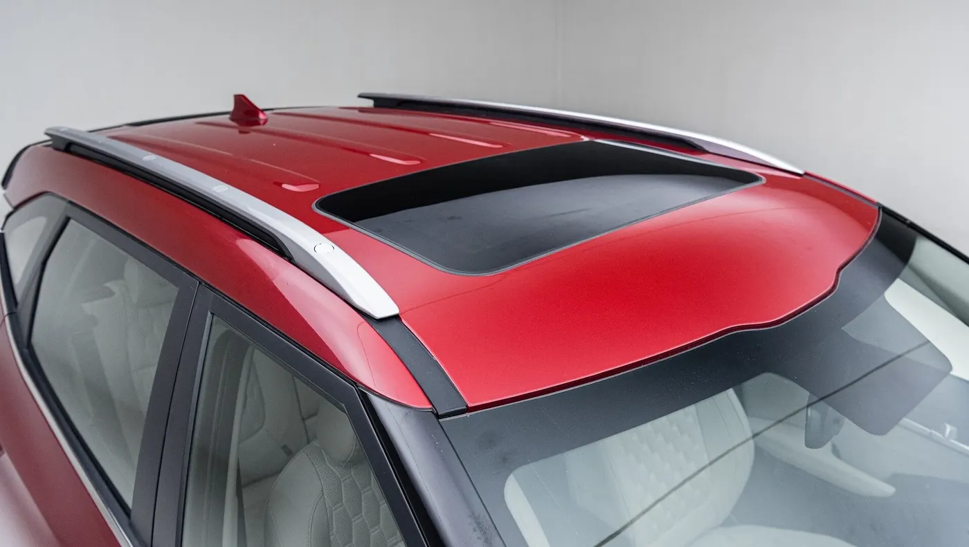
An automobile roof or car top is the portion of an automobile that sits above the passenger compartment, protecting the vehicle occupants from sun, wind, rain, and other external elements. Because the earliest automobiles were designed in an era of horse-drawn carriages, early automobile roofs used similar materials and designs. In later years, many variations on the automobile roof were developed.
These include:
· Convertible roofs
· Roof modules
· Hardtops
· Sunroofs
· T-tops
· Targa tops
· Vinyl roofs
Commonly, the roofs have reinforcements to provide strength to the overall structure and withstand the overhead forces like snow, or roll over etc.
OBJECTIVE:
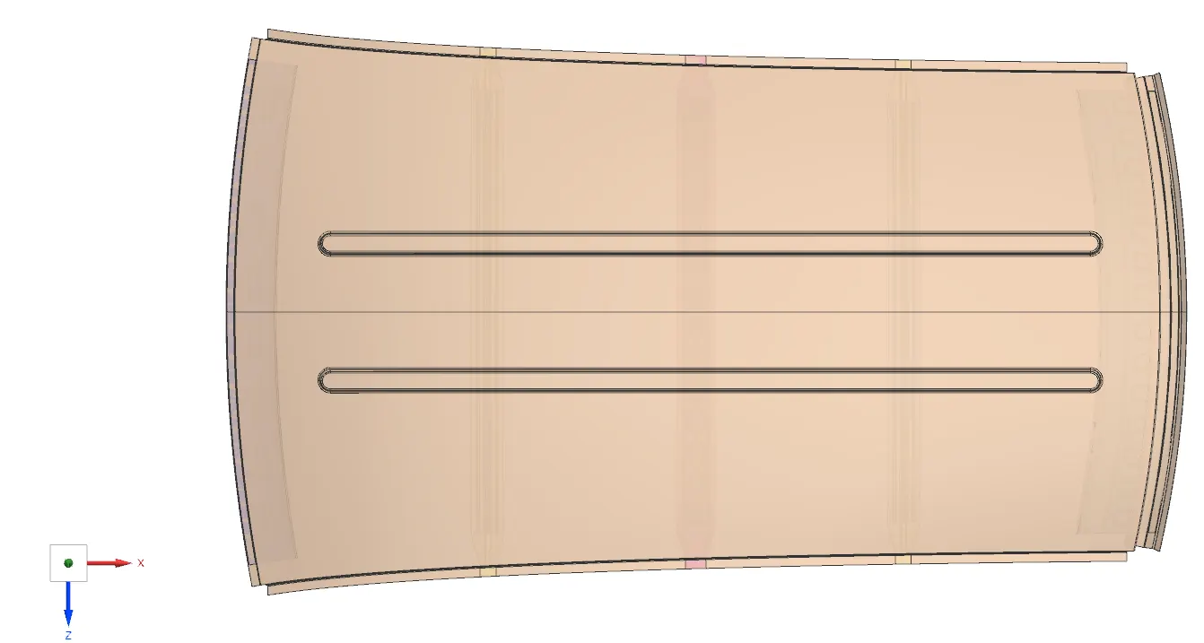
The main objective of the project is to design a roof and associated reinforcements from the existing styling surface. Heat load and snow load calculations will be done on the section of the roof for validating effectiveness of roof reinforcement. Perform the draft analysis for each reinforcement to assess the manufacturability.
MANUFACTURING PROCESS:
The exterior automobile roof panel is made of one large sheet of metal known as a blank which is stamped in a press. If the vehicle has a sunroof, then the sunroof opening is cut out in the midst of the stamping operation. The formed roof is then sent to the body shop where all the parts of the body structures will come together. During the initial assembly process, the BIW is held together with small toy tabs placed throughout the structure.
These toy tabs act as mechanical fasteners which hold the vehicle together while a robot starts to weld the load-bearing structural members together. The front and rear headers play a crucial part in holding the left and right body side outers (BSO) of the vehicle together during this initial assembly process.
The roof panel is commonly one of the last parts of the BIW which is welded onto the vehicle. To reduce complexity in the assembly process, the roof is top-loaded onto the BIW. Once placed on the top of the roof ditch the roof panel is laser brazed on.
laser brazing the roof panel on the car:
In recent years laser brazing the roof panel onto the vehicle body has become increasingly popular since using this manufacturing technique provides a cleaner look by eliminating the need for roof ditch moulding. During laser brazing, nonferrous metals such as bronze alloy are used as filler material.
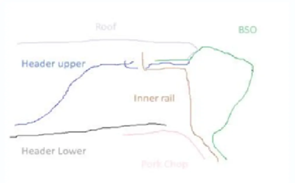
Usually, brazing uses lower temperatures than other welding techniques, which reduces the heat-affected zone and potential damage to the parts being welded. In laser brazing, only filler material melts and joins the joining material. When using the proper technique, you can achieve the same tensile strength of MIG welding by using the laser brazing process and it is less harmful to the parts and easier to control.
ROOF CRUSH TEST:
According to the Federal Motor Vehicle Safety Standard (FMVSS), rollover crashes are some of the most dangerous automobile accidents. About 35% of occupants involved in rollover crashes die, which is more than 7500 people a year. This is because seatbelts on passenger seats are not effective at protecting occupants during a rollover because of their geometry.
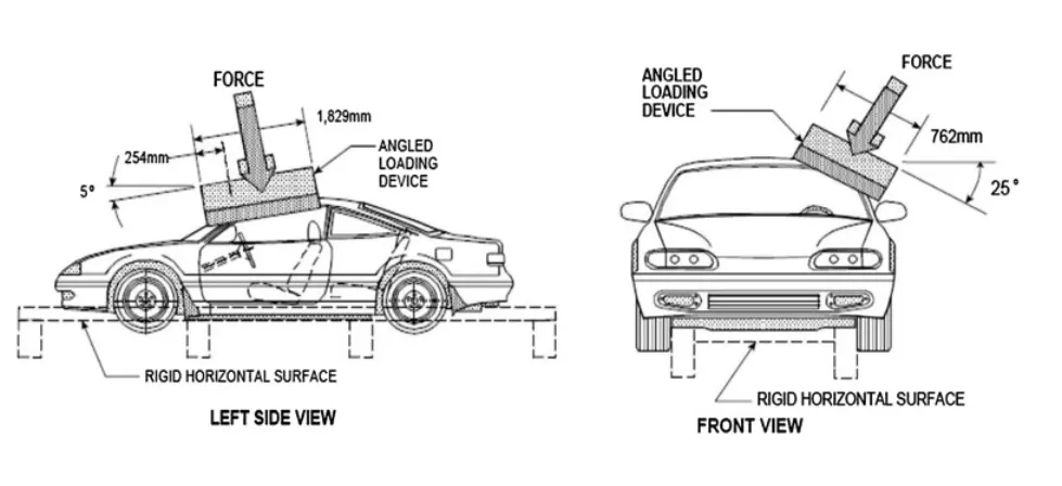
As a result, the FMVSS has developed a standardized test to check vehicle roof structure performance. The latest standard, FMVSS 216a, states that a vehicle that weighs over 6,000 pounds, should be able to withstand a force equal to 3 times the unloaded vehicle weight (UVW) without the roof collapsing (less than 5 inches of deformation).
This test also needs to be conducted on both driver and passenger sides. Since the loading platen is placed forward of the C pillar, the main load-bearing structures during a roof crush test are the A-pillars, B-pillars, front header, and roof rails.
DESIGN PROCEDURE:
For designing roof, we have to create no of roof rails for enough strength to withstand the load. Bow roofs are primarily fixed in flatter region to enhance strength. Front roof and rear roof rails are fixed to the ditch area using spot weld operation. And front, rear bow roof and center roof rails are fixed to roof using mastic sealants. Gap between roof rails and bow roof should be less for Better NVH. Following criteria are taken into account for roof rail design.
· Visibility criteria
· Head clearance
· Curvature study
· Hear distortion and snow load criteria
· Draft analysis
Input given:
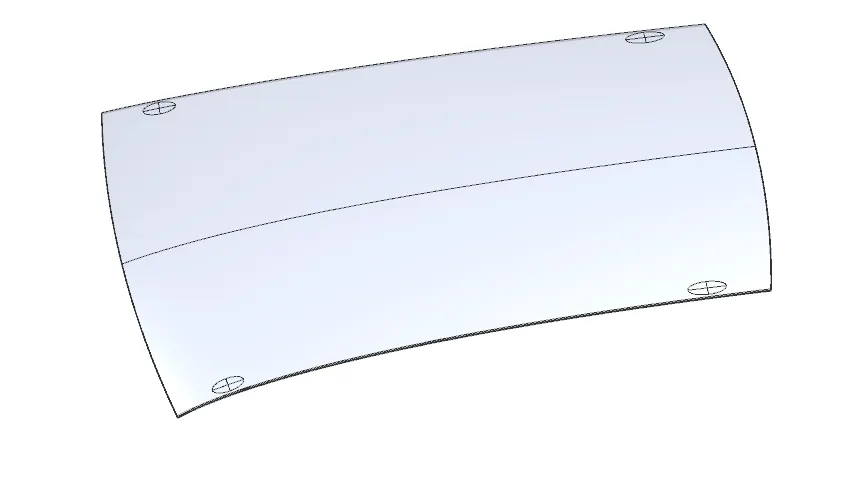
Improved surface
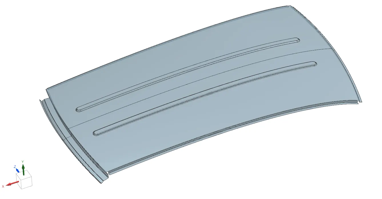
FRONT ROOF RAIL:
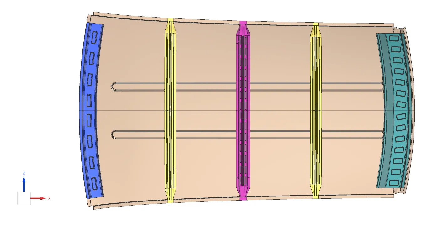
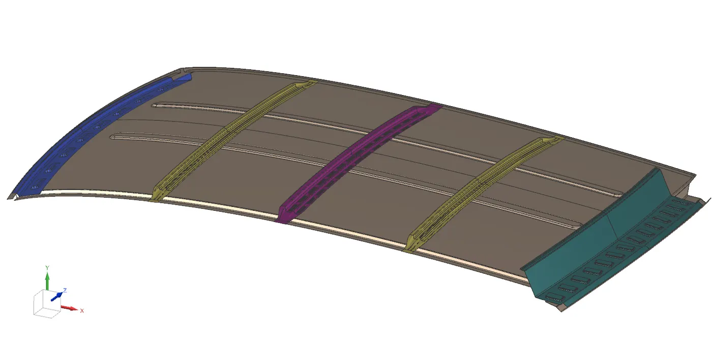
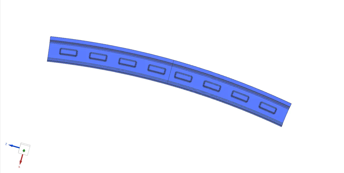
Front roof rail is joining the wind shield glass with roof. It also joins the roof with inner panel and body side outer. The depth of the front roof rail is based on the front visibility criteria, and width of the front roof rail is decided according to head room clearance.
For joining the front roof rail with flange of roof by using spot welding, and we use mastic for joining the front roof rail with the roof.
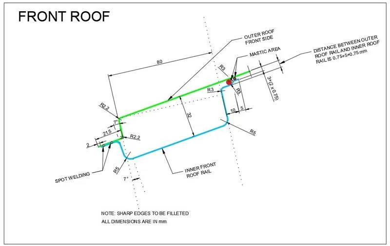
The part created successfully according to the master section. The below image shows the final output of the front roof rail.
REAR ROOF RAIL:
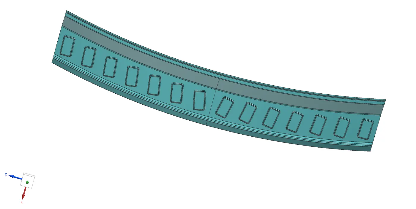
Rear roof rail is joining the back door with roof, and also joins the body side outer. The design consideration for rear roof rail is rear visibility criteria and rear head room clearance.
For joining the rear roof rail with flange of roof by using spot welding, and we use mastic for joining the rear roof rail with the roof.
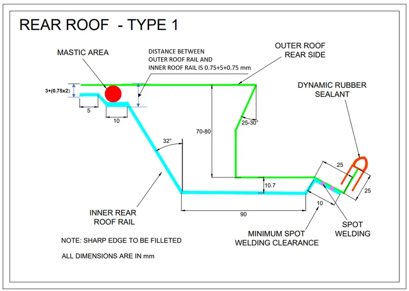
The part created successfully according to the master section. The below image shows the final output of the rear roof rail.
CENTRE ROOF RAIL:
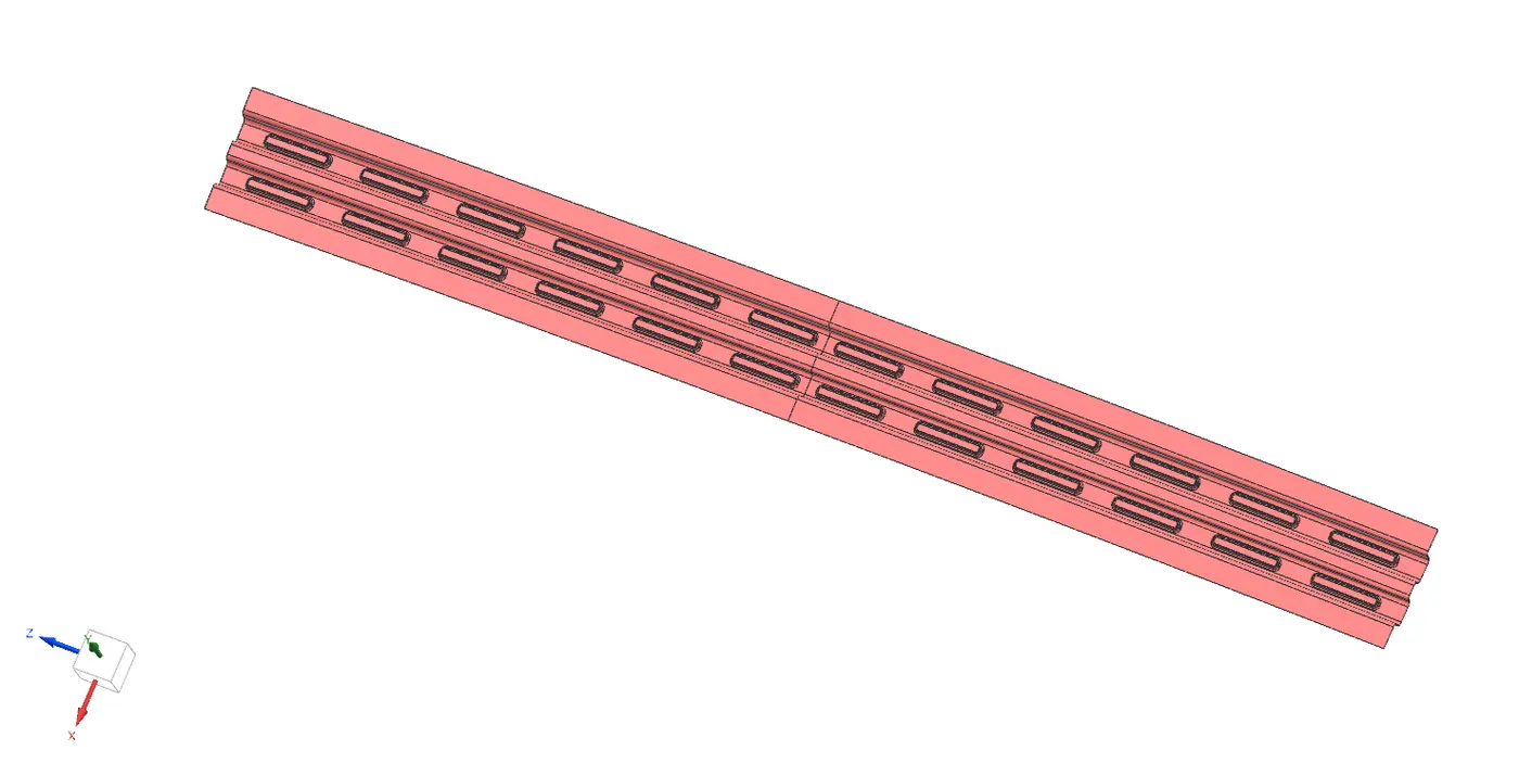
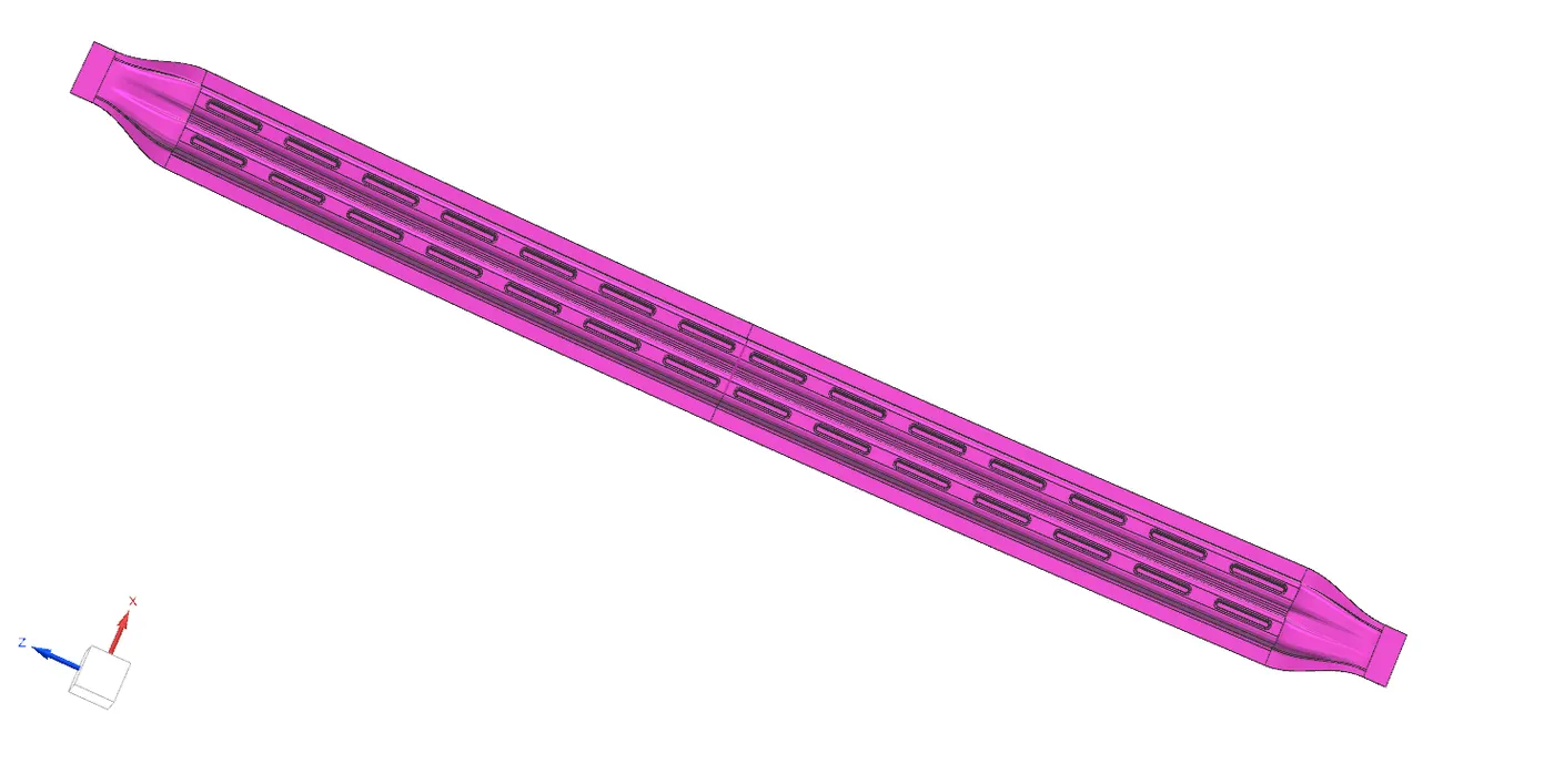
Central roof rail helps in providing effectively support to the flat area of the roof as it is more susceptible to failure under the action of load. Generally central roof rail is placed at the center of the roof which is connected to the B-pillar support structure. This central roof rail helps in adding the strength to the roof during the roll over test.
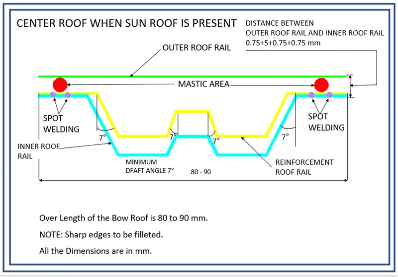
The part created successfully according to the master section. The below image shows the final output of the rear roof rail.
BOW ROOFS:
The Bow roofs are given to improve the torsional stiffness and load-bearing capacity of the roof structure, and overall increase the strength of the roof. The number of bow roofs depends on the overall dimensions of the roof. Longer the roof more the bow roofs are integrated to BIW frame.
The positioning of bow roofs is based on curvature study. The heat distortion criteria and snow load criteria are checked to analyses the position of the bows in various conditions. The bow roofs are attached to the outer panel using mastic sealants.
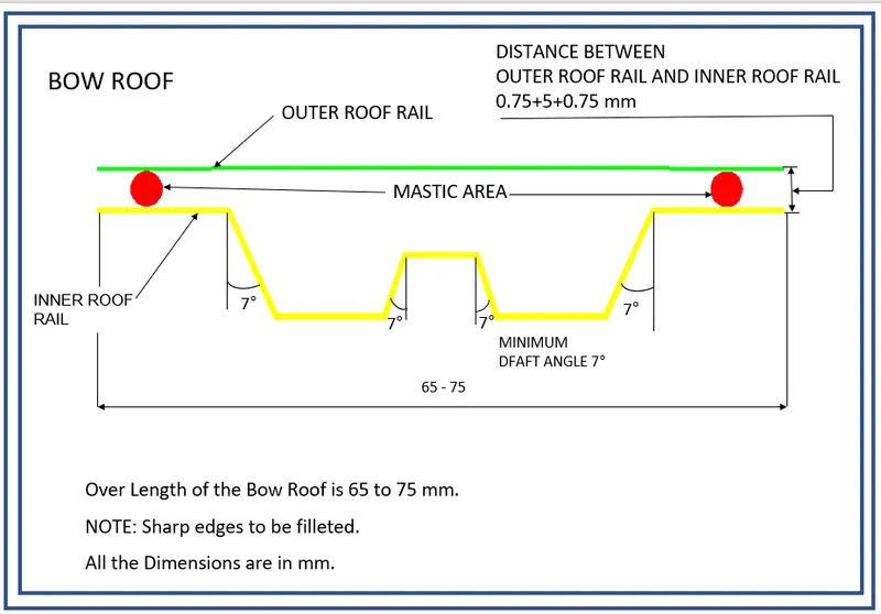
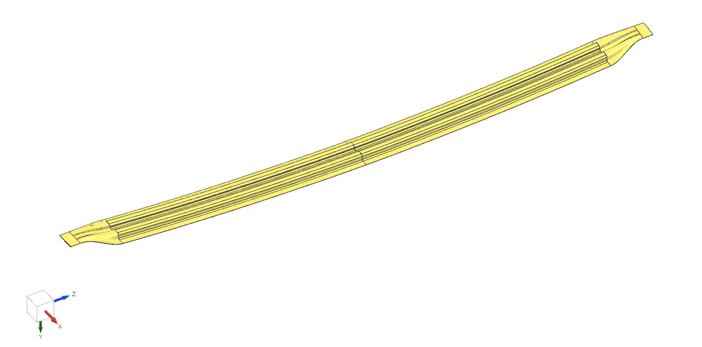
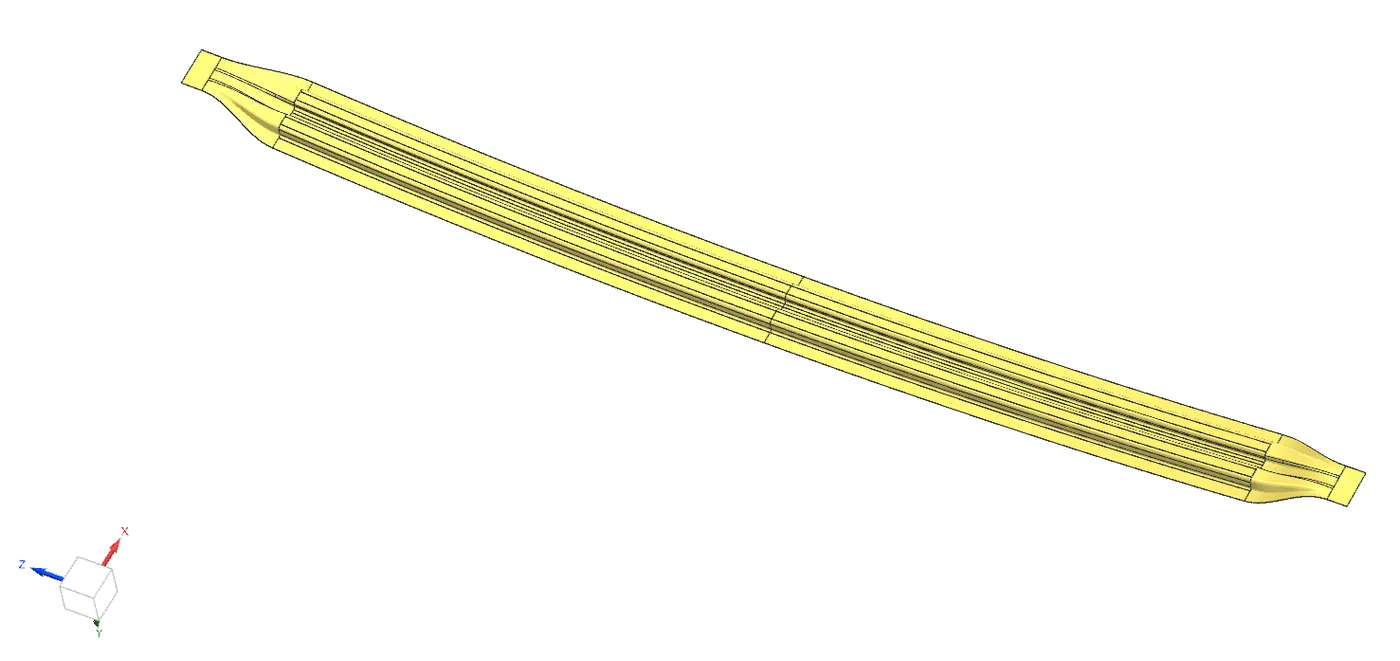
The part created successfully according to the master section. The below image shows the final output of the Bow roof rails.
Bow rail 1
Bow rail 2
HEAT DISTORTION CRITERIA:
Heat distortion temperature is the temperature limit above which the material cannot be used for the structural applications. This study is used to predict the heat distortions temperature at the material where it starts to soften when exposed to a fixed load at elevated temperature.
In order to avoid bending or damages on the roof, based on the heat distortion temperature, this study will predict the bow roof position which helps to strengthen the roof
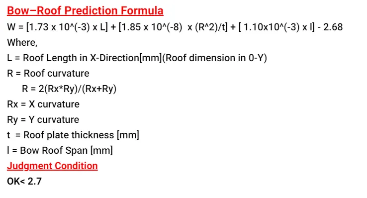
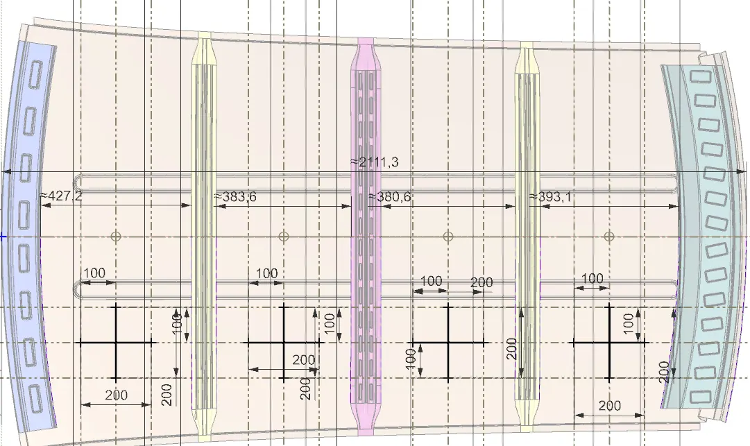
The below table shows us about the designed model is cleared heat distortion test.

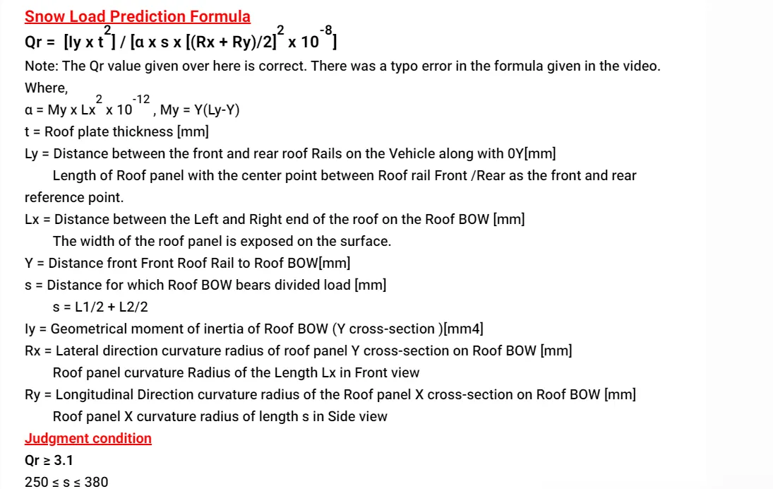
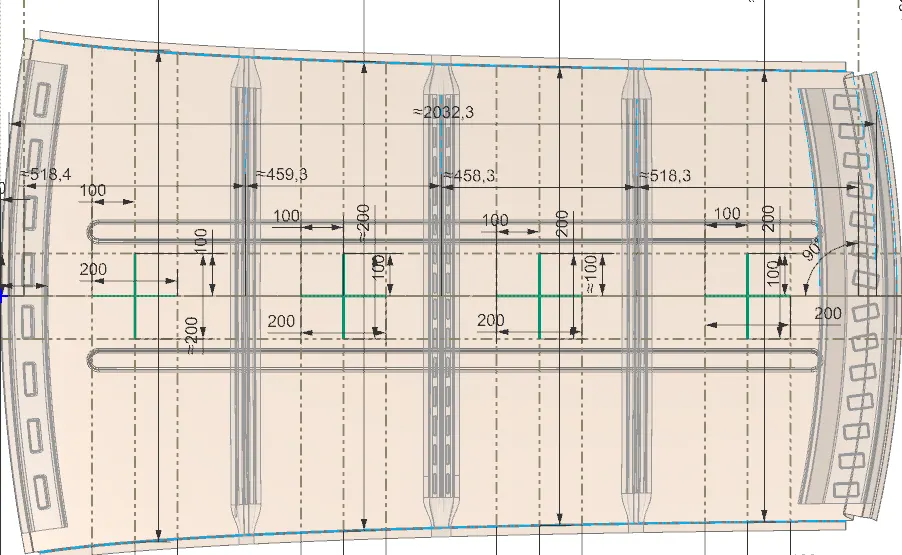
SNOW LOAD CRITERIA:
This test is done to know how is the roof behaving when there is a snow over. normally due to the snow weight the dent will happen. But the roof should be designed in such a way that when the snow is removal the roof should go it its original position. This is the basic requirements for snow load criteria.
Section moment of inertia:
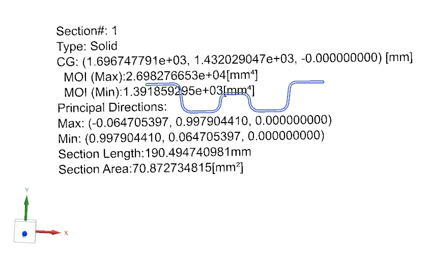
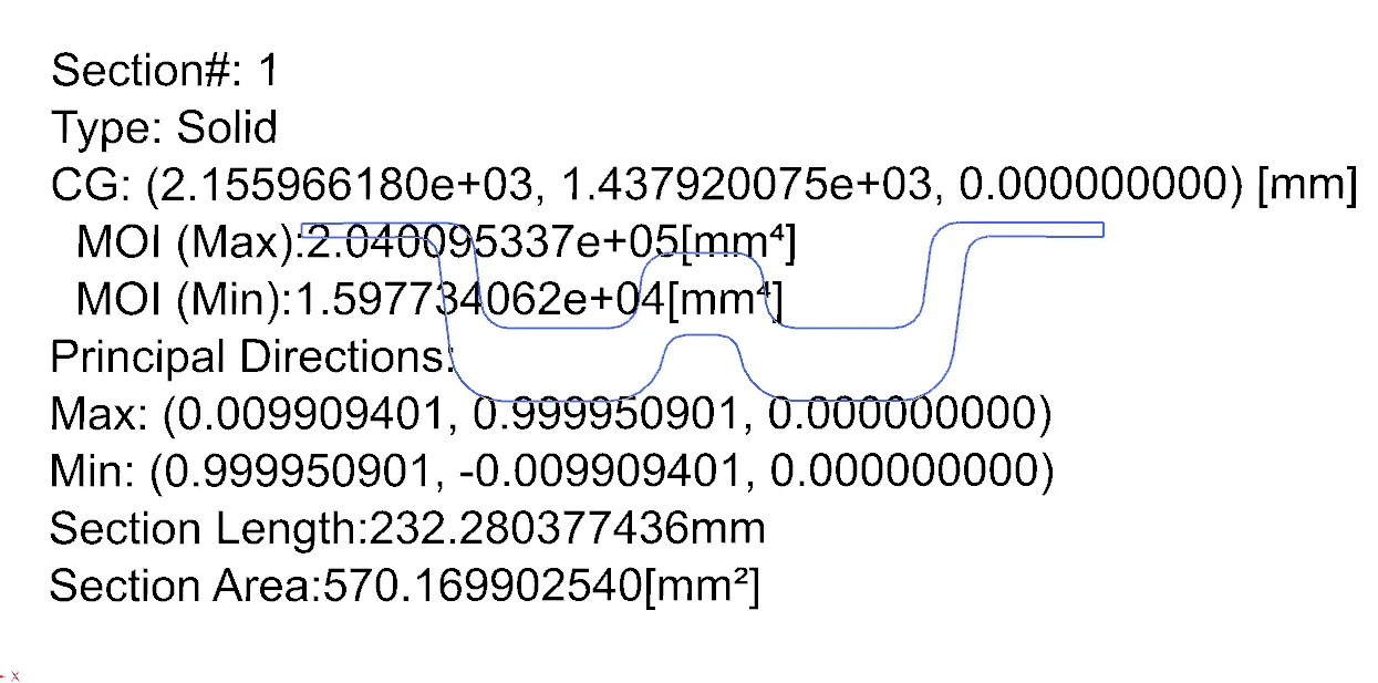
Section moment of inertia is used to predict the amount of deformation and deflection of a part. A higher moment of inertia is preferable as it reduces the amount of deflection for a given force. The thickness of the part and addition of flanges and embosses increase the section inertia of the part. Here the master sections of the roof and roof rails and their section analysis are given.
The elastic section modulus is defined as
S = I / Y
Where,
S = Section modulus
I = second moment of inertia (or area moment of inertia, not to be confused with moment of inertia)
Y = distance from the neutral axis to end most point of the fiber.
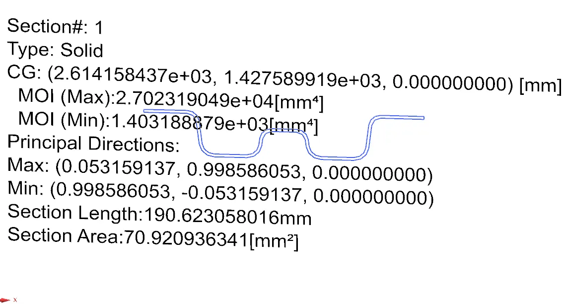
The below table shows us about the designed model is cleared snow load test.

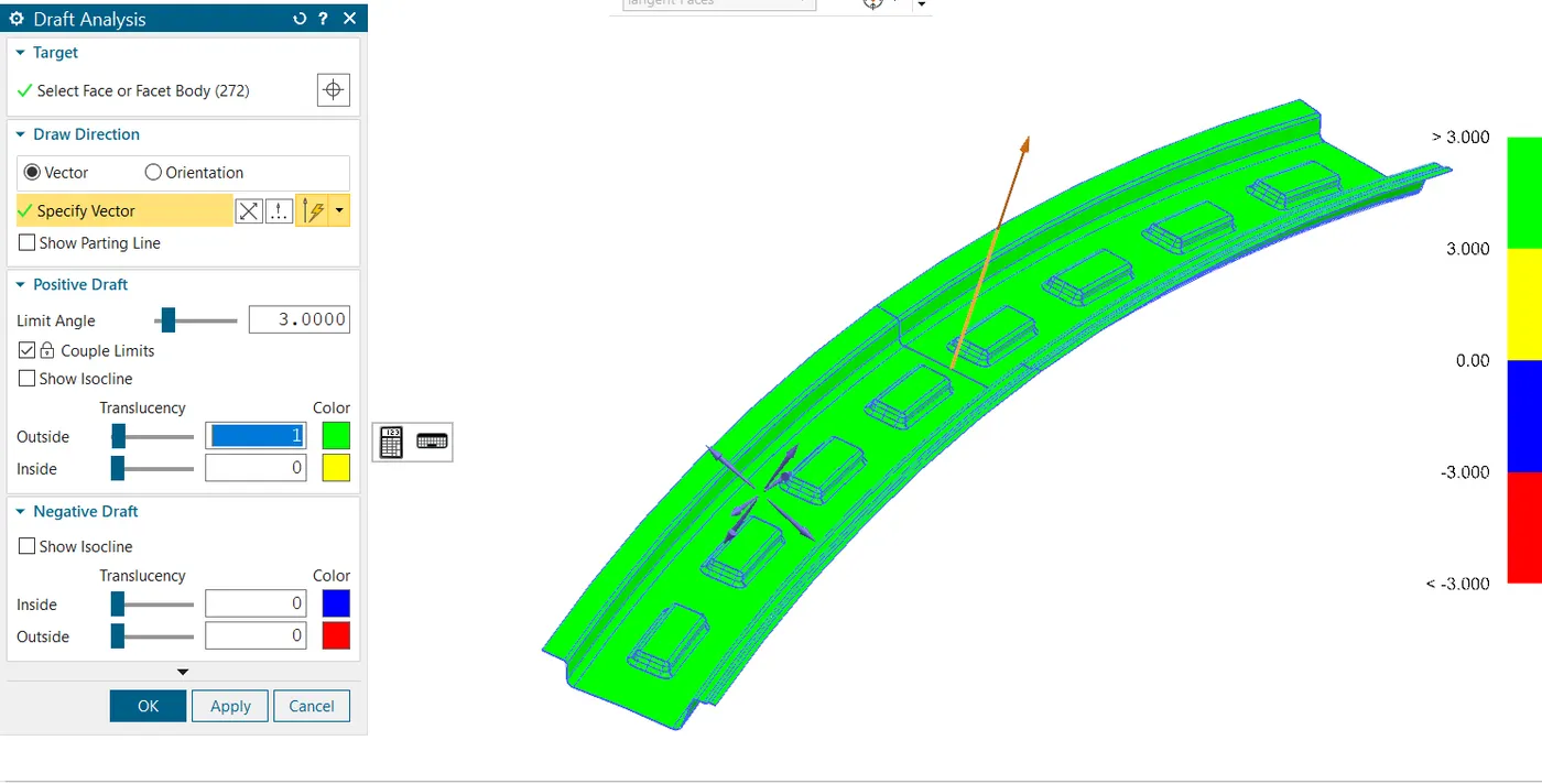
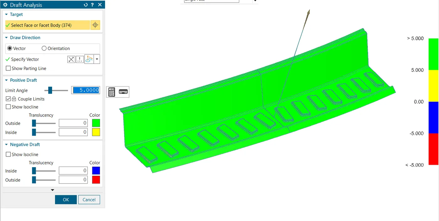
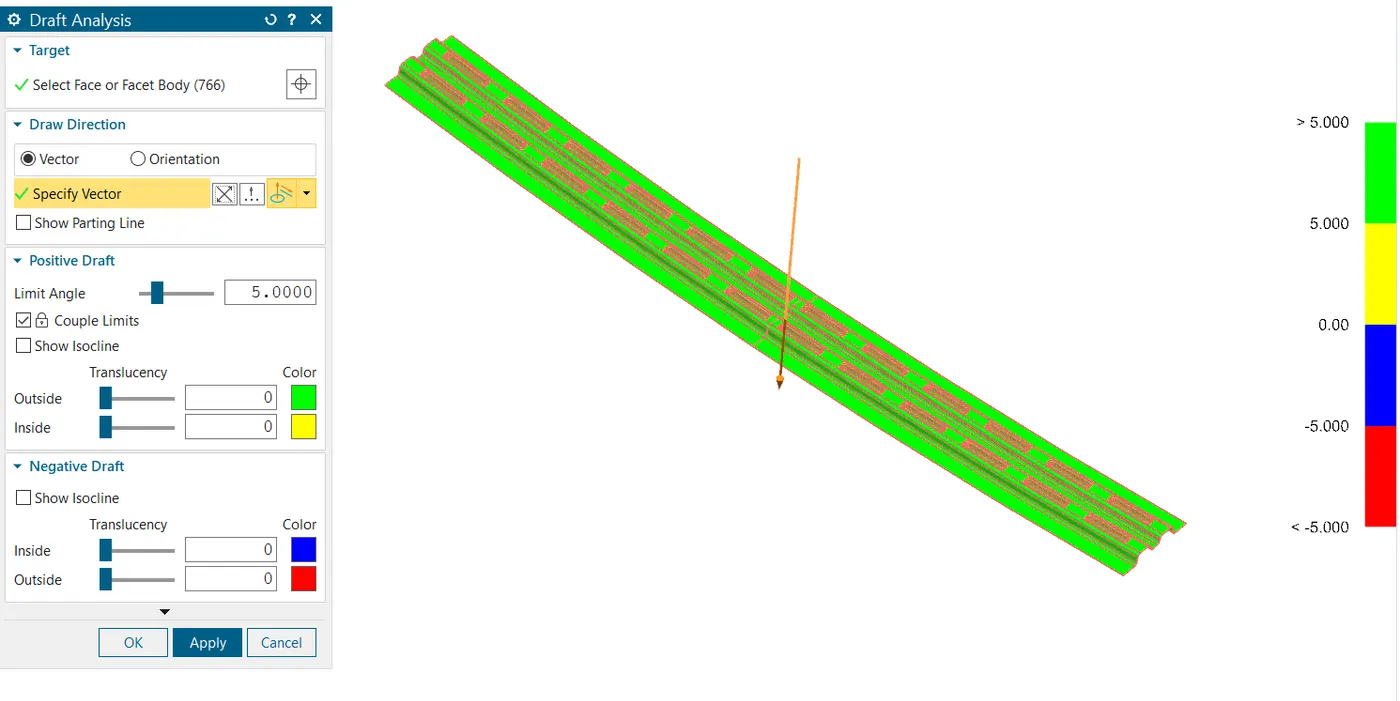
DRAFT ANALYSIS TEST:
FRONT RAIL
REAR RAIL
CENTER RAIL
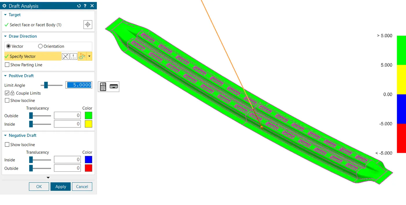
BOW1
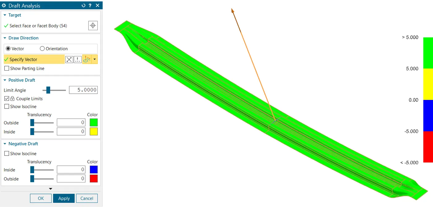
BOW2
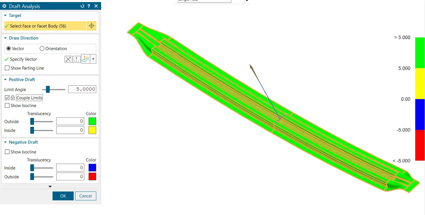
CONCLUSION:
Design of roof was successfully completed using SIEMENS NX as per the given master sections. The position of bow roof rails is as per the standards. Draft analysis & section analysis ensures as the manufacturability of every component.