Roof Design
AIM :
To develop the roof assembly with the given Class A surface and add the necessary reinforcement to increase the structural rigidity and add Flanges to the outer panel of the roof to mount with the Body side Covers. And perform some calculation to find the Roof reinforcement part positioning for heat distortion and snow load values.
INTRODUCTION :
Roof is the Top most part of an any closed body vechicle it can be made up of material like steel, Aluminum , carbon fibre, fiber glass and plastic depending upon the requiement. Roof can be in various types with their own prons and cons. The roof type , Material selection is all undergoes under the budget and the usage of the vehicle and country safety regulation.
Roof can be play a major role in the overall look of an vehicle. Considerations include color, lines, and how it integrates with other parts of the car. The aerodynamic of an vehicle is also important factor to define the roof shape. Additional embosses and stiffners are introduced under the roof to increase its structural integrity. The Positioning of stiffiner is also critical to act as support at a sametime there is a limit of usage of stiffner and again its affect the overall weight of an passenger vehicle. Other factors to be remember in the development of Roof are Safety ( side impact, Rollover protection), Insulation to reduce the Noise, heat, water and other environmental affects, anufacturability, assembly sequence, Recyclability and sustainbility.
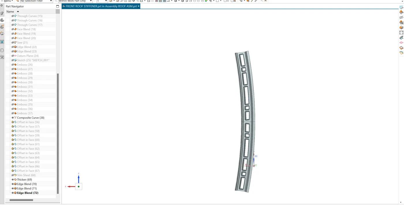
Stiffener is placed in the Front, centre and rear end of the roof to increase the strength.
ROOF RAILS :
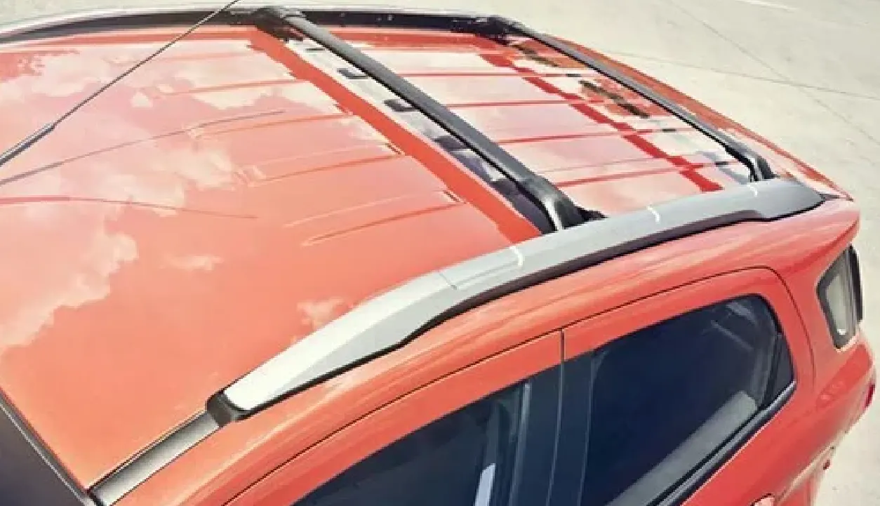
Roof rails are the structural elements placed on the top of the roof to increase its structural integrity and support cargo. Rails are especially used in off road vehicle,SUV and crossover vehicle. In Rollover event it maintain the integrity of the roof shape. It is commonly use Aluminimum material due to its light weight and it commonly manufacured by extrusion process.
CAR ANTENNA :
It is a device to receive and transmit the radio frequency in mordern days it is play a major role in GPS signals, FM radio and Autopilot or ADAS. These antennas are part of a complex network of sensors and communication systems that help the vehicle navigate, detect obstacles, and communicate with external systems.
DITCH AREA :
Ditch area run along the side of roof. These area helps the rainwater runoff to the rear edge or down the sides to prevent the pooling on the roof . It preven the cabin from water and provide mounting feature to the roof rails.
FRONT ROOF STIFFENER:
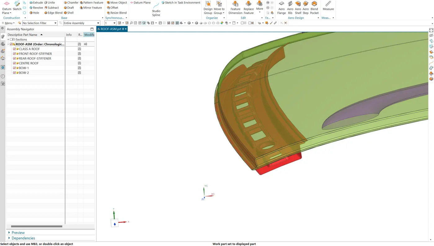
Front end stiffener is more critical part among other reinforcement it play's a major role in driver visibility, head room clearance, Frontal impact absorption and Head room clearanceserve mounting for front windshield and sunroof.
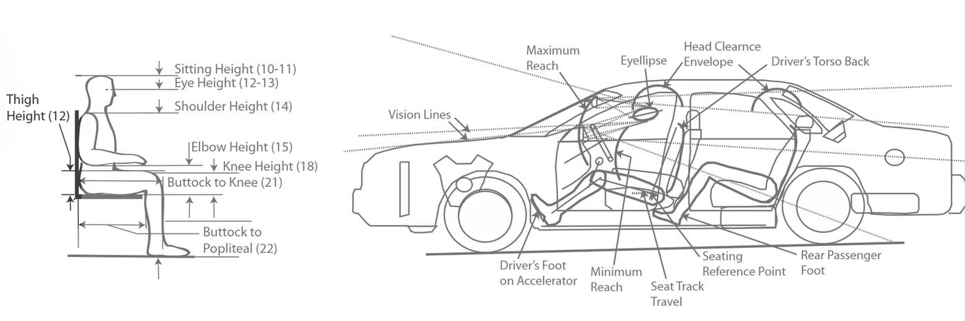
- Head room clearance is an vertical space between the seat position and the ceiling of the vehicle. The clearance range is minimum in sports cars compared to SUV, sedan model. Vehicle with sunroof or monoroof may have slightly reduced clearance due to additional required features.
- Visible criteria, it is important to reduce the blind spot to the driver when he sitted in the seat and we need to ensure the clear visiblity to the surrounding, rear and side mirror. While coming to the placement of side mirror and windows sizes is to followed by the FMVSS standards. In recent time ADAS is introduce to enhance the visiblity and safety of an vehicle.
- Frontal Impact, the material is to be selected with lightweight and it should designed to have necessary embosses to increase its rigidity and absorp the forece and direct the impact towards outward direction to reduce the risk in the cabin.
- Master section , it is a 2D cross sectional view of an particular component to clearly provide the design intent and spatial relationship between various components. This ensure the overall design intent, assembly, manufacturability, structural strength, ergonomic of an final product. It is commonly generated and improved by the carry over study. Here we have a master section for all the stiffeners to the roof product.
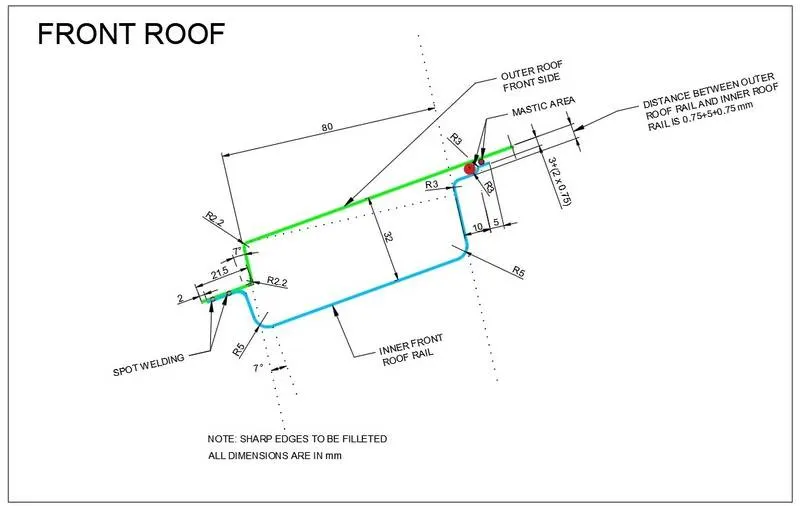
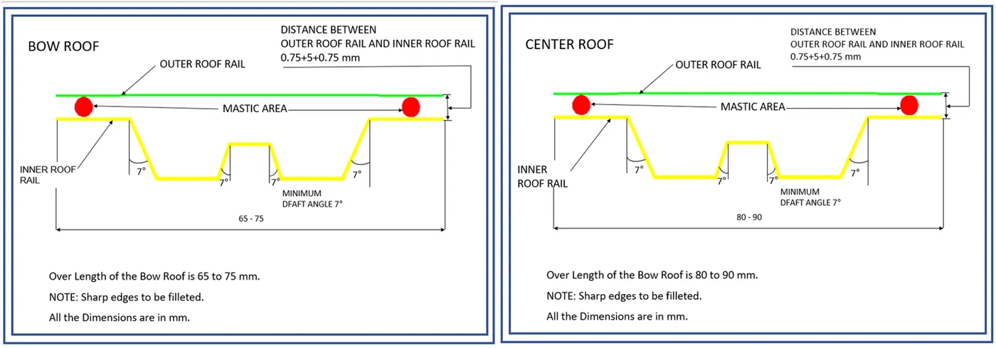
From the master section the minimum bending radius should be maintain R2.2 in outer panel. And the minimum flange should be maintain 21.5 mm, the reinforcement panel should be maintain minimum 32 mm depth and the length is 80 mm. Both the upper and lower panel is spot welded to make it has an single part.
As per Sheet metal standards, the minimum inner bend radius should be vary with thickness and material factors but the universally accepted R value is 2 times of the thickness. where this rule is not followed for higher thickness plates the value of inner bend is always higher for higher thickness and lower for minimal thickness. According to DFM other than manufacturing feasibility value can be maintain 3 three times of the thickness , to increase the tool and die lifecycle and the stress concentration in the product also much better.
REAR ROOF STIFFENER:
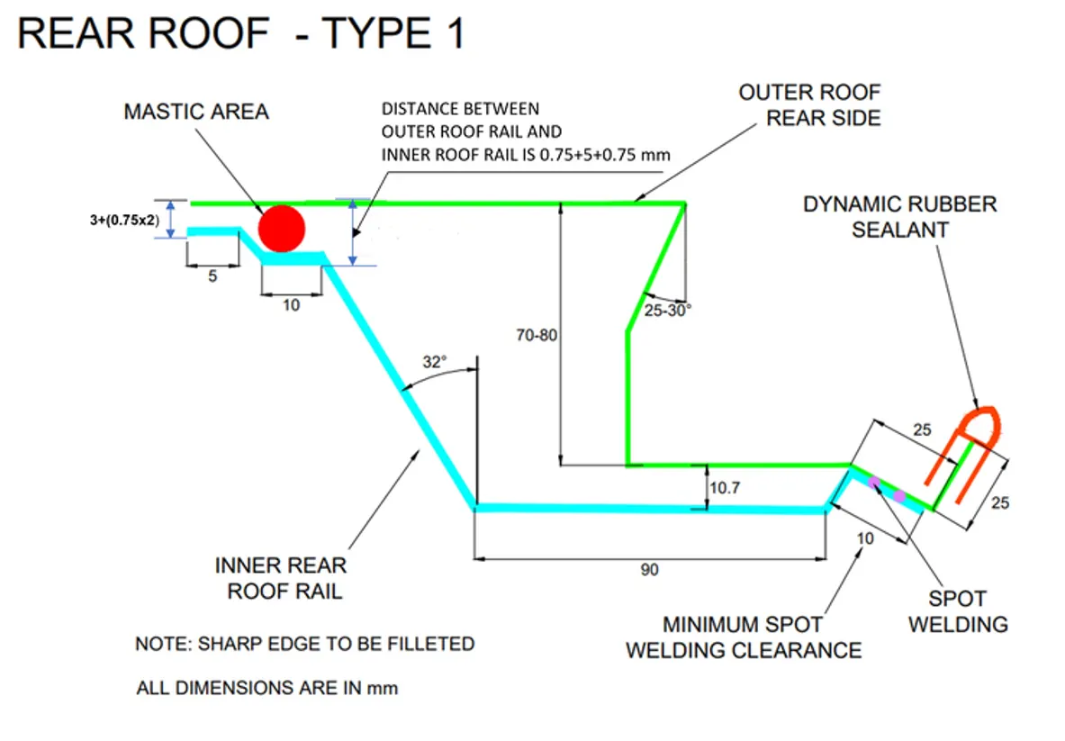
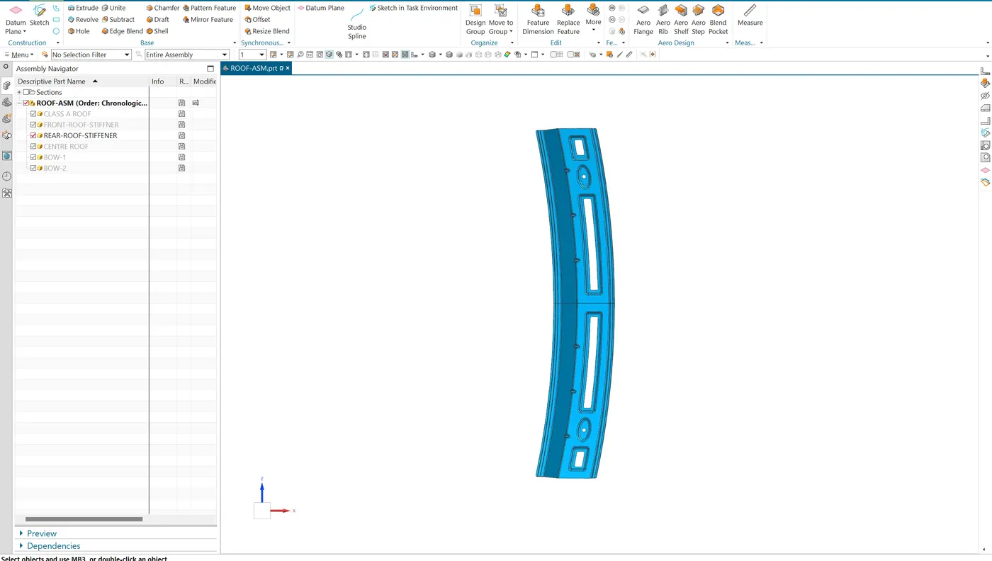
Rear roof stiffener is also designed with the proper head room clearance for the passengers and it plays in the visibility criteria. The master section is provided to develop the flanges. The rear stiffener is spot welded to the outer roof panel and at the end the rubber sealant is used to improve the ingress protection and act as a cushion to rear windshield. From master section it is clearly shows that the minimum flange length 10 mm for proper spot welding process.
CENTRE ROOF & INTERMEDIATE ROOF STIFFENER :
Stiffener is an structural component used to reinforce or improve the strength of a panel, beams or other structural component from bending, twisting, Buckling and deformation under loaded condition. Stiffener increase the rigidity and distribute the load along the surface of the component to reduce the permanent deformation. Apart from designing the positioning of the stiffener is also important, it leads to maximum component are getting placed it will directly affect weight, cost of the vehicle. So researches comes up with various definition to the positioning, here we see the heat distoration and snow load calculation to find the position of the stiffeners.
Centre stffener is necessarily used in the vehicle but intermediate stiffener is may be a choice it all comes up with some calculaltion and Vehicle length. Roof Stiffener are placed in transverse and Longitudinal direction of the length of vehicle. The transverse stiffener is much good in stiffness and rigidity. For Vehicle like SUV, sedan and vans needed additional stiffener to maintain the rigidity. "A" segment car's have a single stiffener due to its shorter length value less than 3699mm, e.g : Alto, Alto K10, Celerio.
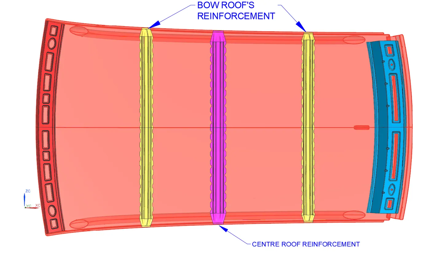
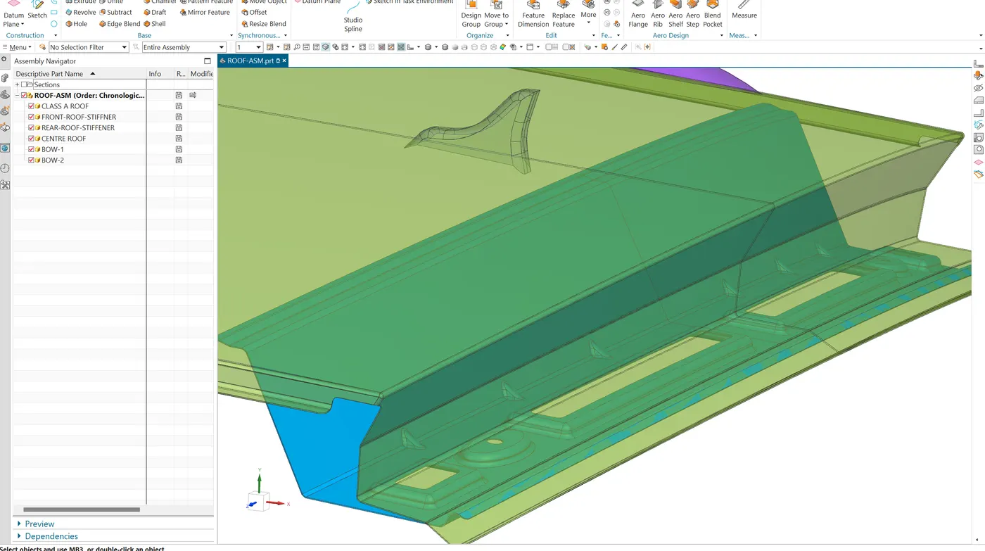
Main roof rail is placed near to the Centre of an layout and other rails placed mid-distance individual between the rails. Commonly sheet metal components are joined by spot or run welding due to aesthetic requirement here it should joined to the upper panel by using adhesion sealant mastic . These have a good sealant and damping property between steel's. It is also drastically reduce the NVH of an vehicle. Mastic can be appiled at a interval of minimum 80 diameter.
Here the following master section for the centre and interemediate stiffeners.
MOULD DRAFT ANALYSIS :
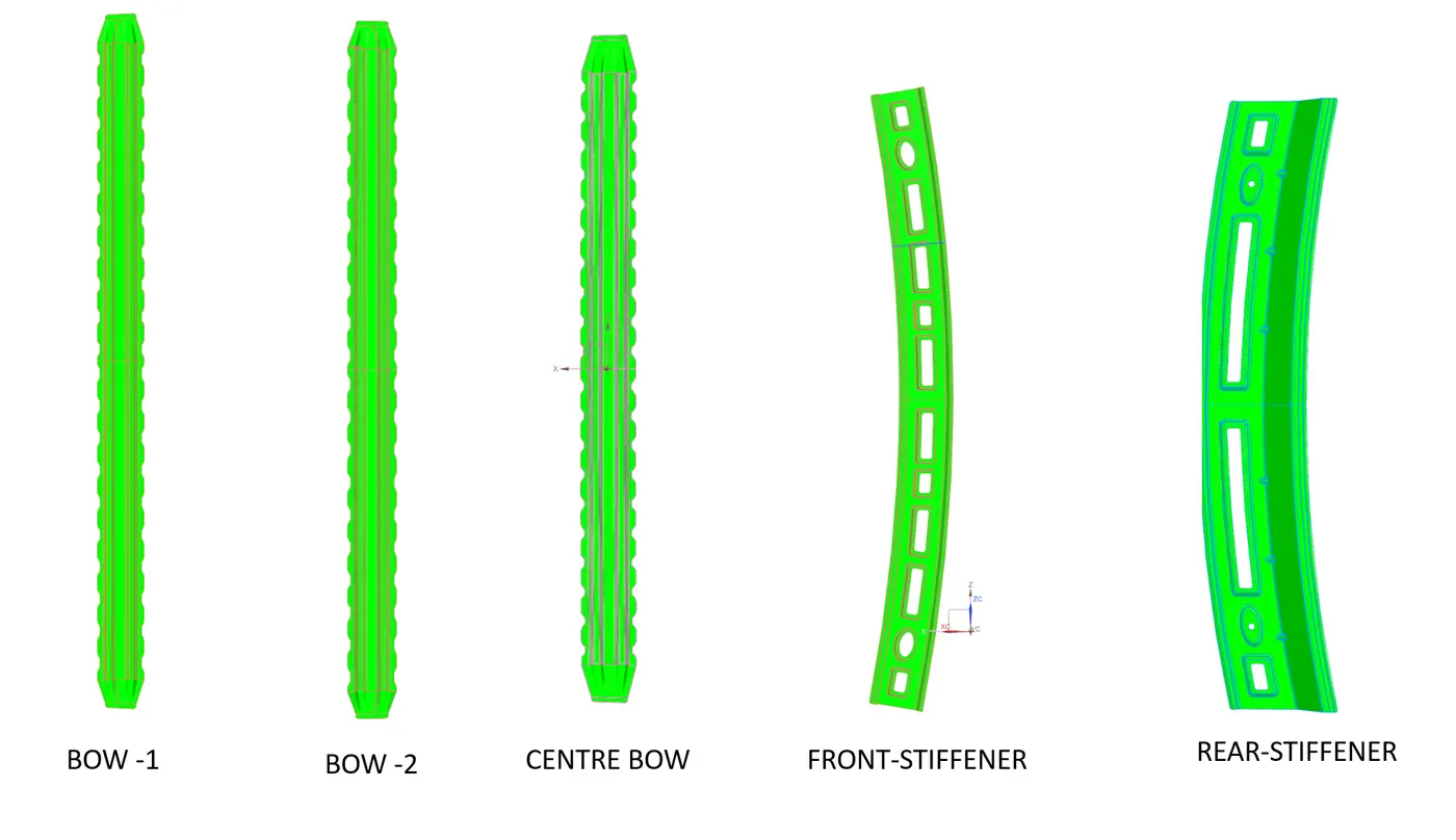
Draft analysis is a technique used to assess the ease of removal of part from the tool and dies and reduce the wear and tear of the component. Draft angle is applied to the vertical flanges or features of the product. It is used in the process of using Mould and dies tools whatever the material like steels(SS, Al, HR, CR) or plastic. The draft angle should be choosen by the material properties and deep drawing dimension. Additional process can be undergone if there is any additional embossess or cutouts. In order to shut-off angle is also important in the overall process where it is an angle between the mould tool and die to avoid the coliision between the tool and die's.
ROOF DESING AND STIFFENER POSITIONING CALCUALTION :
HEAT DISTORTION :
Heat distortion in a car roof refers to the deformation or warping of the roof material due to exposure to high temperatures. This phenomenon occurs when the heat applied to the roof, whether from external sources like the sun or internal sources such as welding during manufacturing, exceeds the material's thermal tolerance, causing it to lose its original shape or structural integrity. Heat distortion takes place by the material properties, thermal expansion, manufacturing process and environmental factors.
Distortion can be calculated by using,
W = [1.73 x 10^(-3) x L] + [1.85 x 10^(-8) x (R^2)/t] + [ 1.10x10^(-3) x l] - 2.68
where,
L = Roof Length in X-Direction,
R = Roof curvature , R = 2(Rx*Ry)/(Rx+Ry) , Rx = X curvature, Ry = Y curvature
t = Roof plate thickness [mm], l = Bow Roof Span [mm]
To measure the Rx and Ry curvature values , intitlally draw a sketch on the surface of the roof and extract the position of the roof and define the lines and points at an interval of 100mm and join the arc with the help of three points.
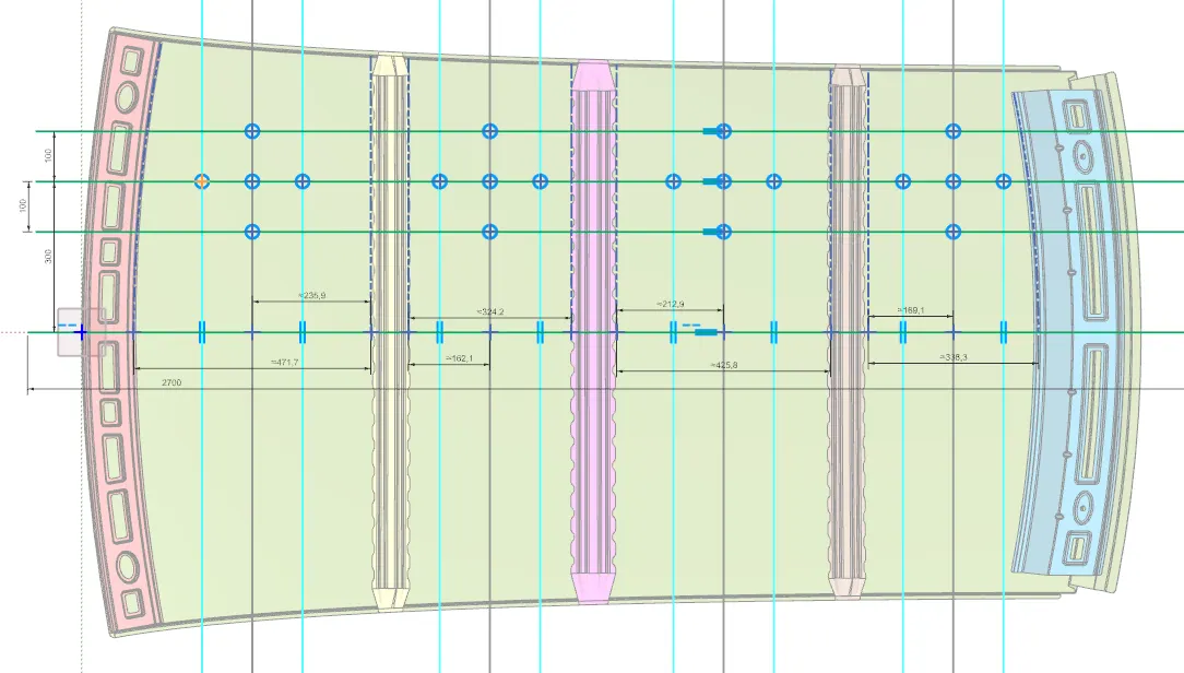
Project the points on the surface ,
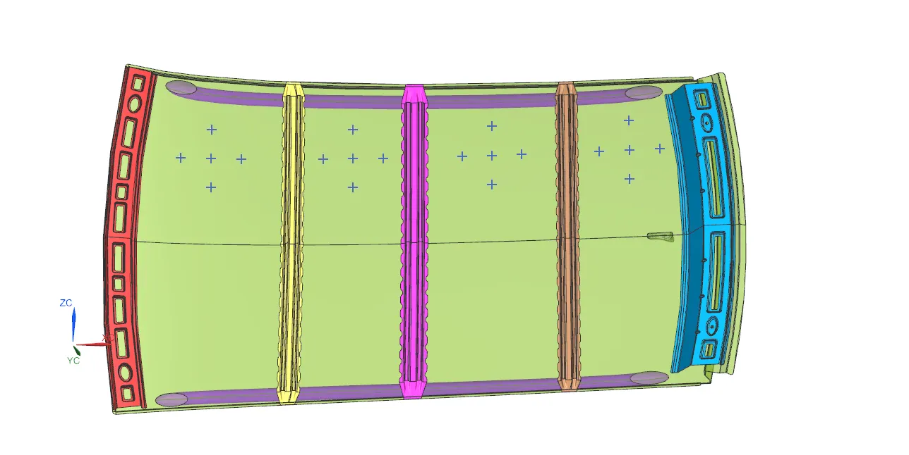
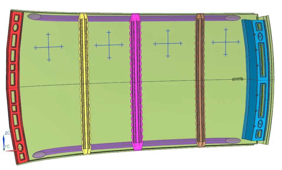
The judgement factor is W < 2.7 , This value ca be vary by the Manufacturer.
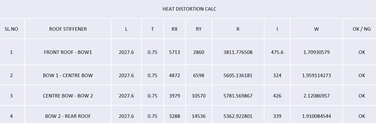
Hence, all the roof positioning are ok.
SNOW LOAD CRITERIA :
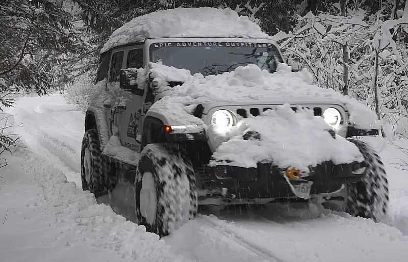
Snow load criteria in car roof design refer to the standards and considerations manufacturers must follow to ensure a vehicle’s roof can safely bear the weight of accumulated snow and ice. This is especially important in regions with heavy snowfall, where snow accumulation can exert significant pressure on the roof structure, potentially leading to damage or collapse.They are influenced by the typical weather conditions in different regions. Vehicles intended for use in snowy or mountainous regions may need to meet more stringent snow load requirements
The FOS value can be calculated by the equation ,
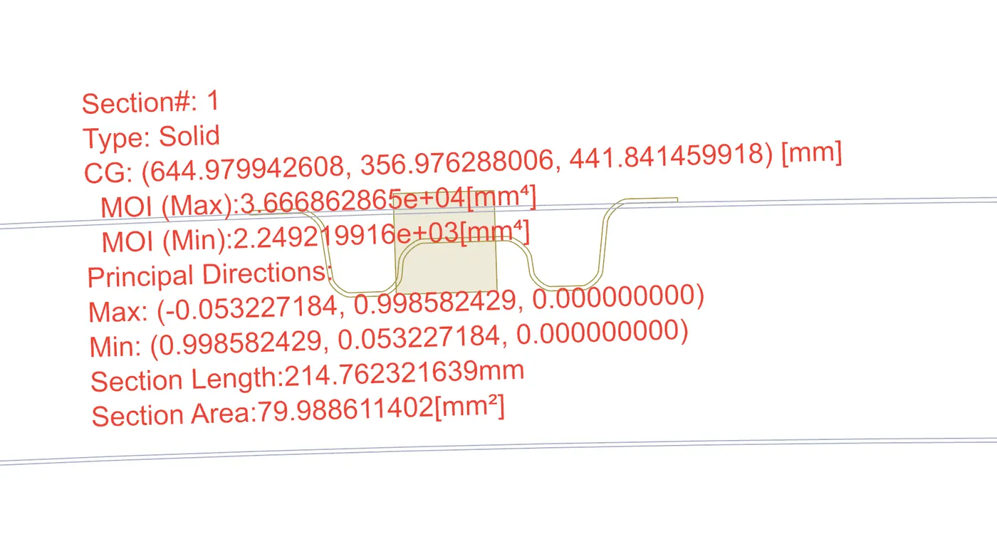
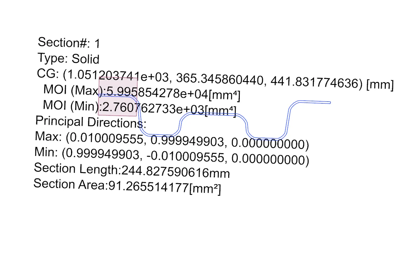
Qr = [Iy x t2] / [α x s x [(Rx + Ry)/2]2 x 10-8] , Qr ≥ 3.1.
where, t = Roof plate thickness [mm], α = My x Lx2 x 10-12 , My = Y(Ly-Y)
Ly = Distance between the front and rear roof Rails on the Vehicle along with 0Y[mm].
Lx = Distance between the Left and Right end of the roof on the Roof BOW [mm].
Y = Distance front Front Roof Rail to Roof BOW[mm].
s = Distance for which Roof BOW bears divided load [mm], s = L1/2 + L2/2.
Iy = Geometrical moment of inertia of Roof BOW (Y cross-section )[mm4].
Rx = Lateral direction curvature radius of roof panel Y cross-section on Roof BOW [mm].
Ry = Longitudinal Direction curvature radius of the Roof panel X cross-section on Roof BOW [mm].

BOW ROOF -1 INERTIA :
CENTRE ROOF INERTIA :
BOW ROOF-2 INERTIA :
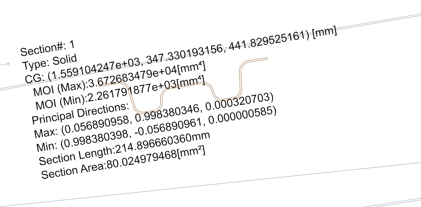

Hence the roof stiifeners are under the snow load conditions.
CONCLUSION :
The roof panel is designed along with the reinforcement rails according to given master section and design considerations. The heat distortion and the snow load calculations are made and found the positioning of the stiffnerers.
LINK : https://drive.google.com/file/d/1cSUtTOaqPcQWcyPRLPG0PHBz8UEjbf1u/view?usp=sharing