Roof Design
Roof Design
CAR ROOF:
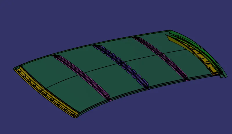
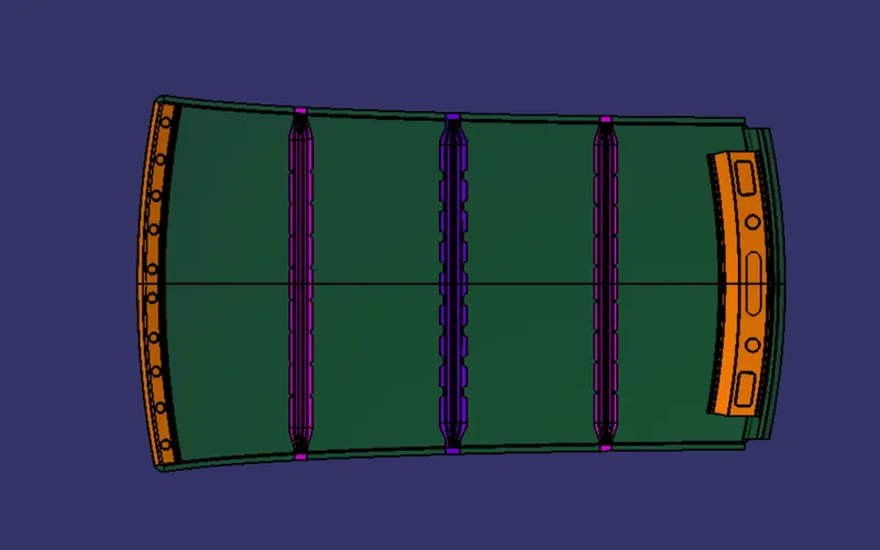
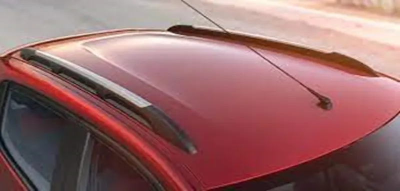
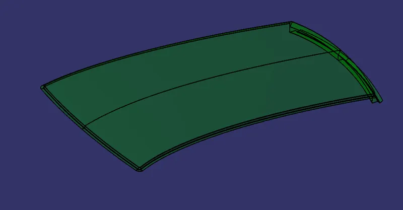
An automobile roof or car top is the portion of an automobile that sits above the passenger compartment, protecting the vehicle occupants from sun, wind, rain, and other external elements. Roof is the structure above the wind shield glass having the reinforcements to provide the strength to the overall structure.
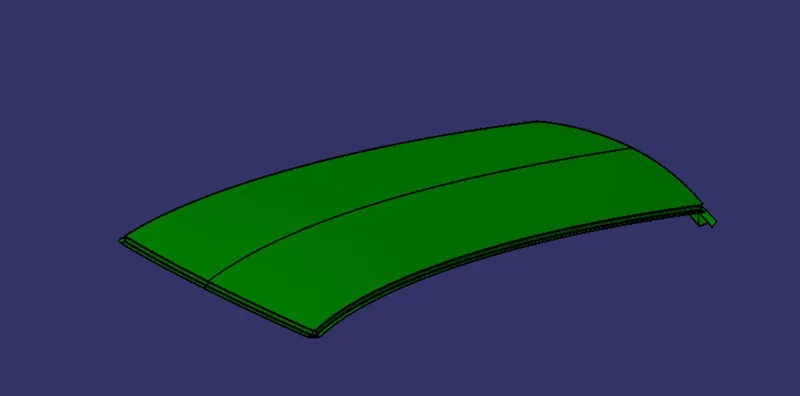
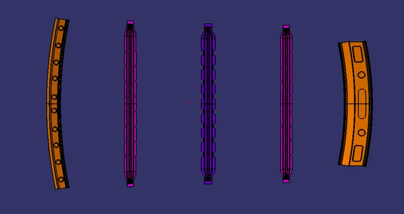
Different types of reinforcements that the car has are:
- Front roof rail
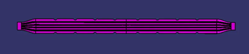
- Bow roofs
- Central roof rail and
- Rear roof rail
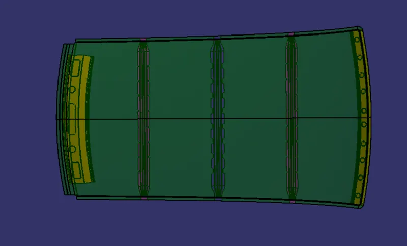
Front roof rail:
Front roof rail is the one which joins the wind shield glass , body side outer panel.

Rear roof rail:
Rear roof rail is the one which joins the back door and the body side outer.
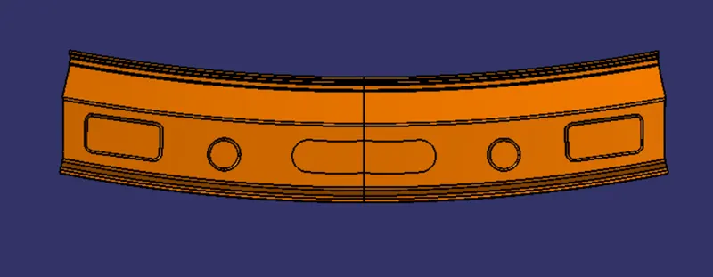
Central roof rail:
Central roof rail helps in providing effectively support to the flat area of the roof as it is more susceptible to failure under the action of load. Generally central roof rail is placed at the centre of the roof which is connected to the b-pillar support structure. This central roof rail helps in adding the strength to the roof during the roll - over test.

Bow roofs:
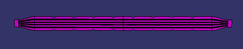
The bow roofs are given to improve the torsional stiffness and load bearing capacity of the roof structure. The number of bow roof present is depending on the overall size of the roof. Presently in this project two bow roofs are added.
Heat Distortion Criteria
This calculation is performed to check the strength of the roof at a certain load with a certain temp. This study will predict the position of bow roofs.
W = [1.73 x 10^(-3) x L] + [1.85 x 10^(-8) x (R^2)/t] + [ 1.10x10^(-3) x l] - 2.68
Where,
L = Roof Length in X-Direction[mm](Roof dimension in 0-Y)
R = Roof curvature
R = 2(Rx*Ry)/(Rx+Ry)
Rx = X curvature
Ry = Y curvature
t = Roof plate thickness [mm]
l = Bow Roof Span [mm]
Judgement Condition - OK<2.7
Procedure
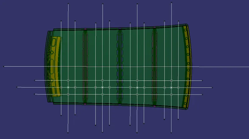
1) We create a 0Y line on the top of the roof.
2)We sketch a -3Y which is 300m below from the 0Y line
3) We sketch 2 line on the both side of the -3Y line at 100mm distance
4) We sketch a line in the middle of the FR and BOW ROOF 1,BOW ROOF 1 and CR, CR and BOW ROOF 2,BOW ROOF 2 and RR.
5) We sketch 2 line on the both sides of the middle line.
6)we create intersection points of the line and project it on the roof then measure the Rx and Ry distance.
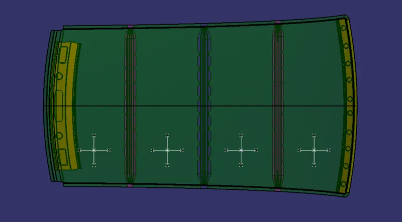

Hence This model has passed the heat distortion criteria.
SECTION MODULUS CALCULATION:-
It measure the strength of any area of an object, Greater the value of section modulus, greater will be the strength of the section. The section modulus depends upon the moment of inertia which again depends not only on the total area of the cross-section but also on the disposition of the area with respect to neutral axis.
Section Modulus Formula (S) =I/Y
Where I =Second Moment of Inertia
Y= Distance from the neutral axis to any given fibre
Section Modulus of each part of the roof are calculated below:-
Front Roof Rail
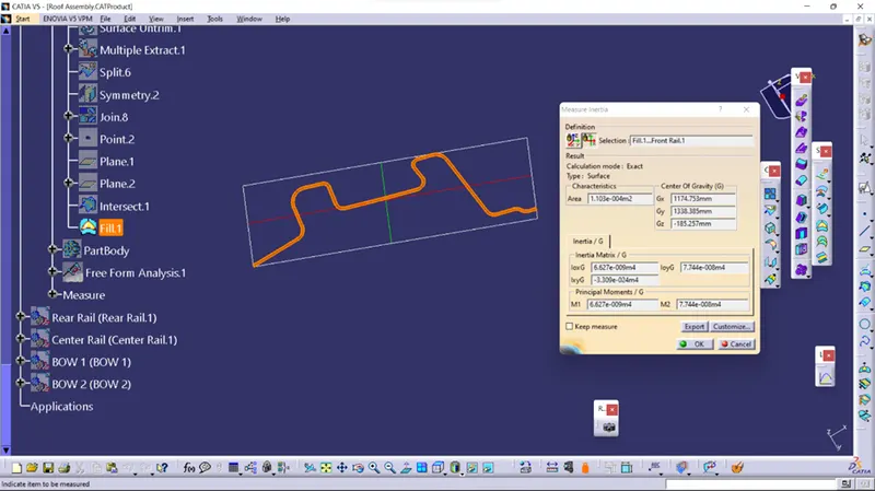
I = 6.627 X 10⁻³mm4
Y = 95.249 / 2 = 47.624mm
S = I / Y = 6.627 X 10⁻³ / 47.624
S = 13.915 X 10⁻⁵ mm3
Rear Roof Rail
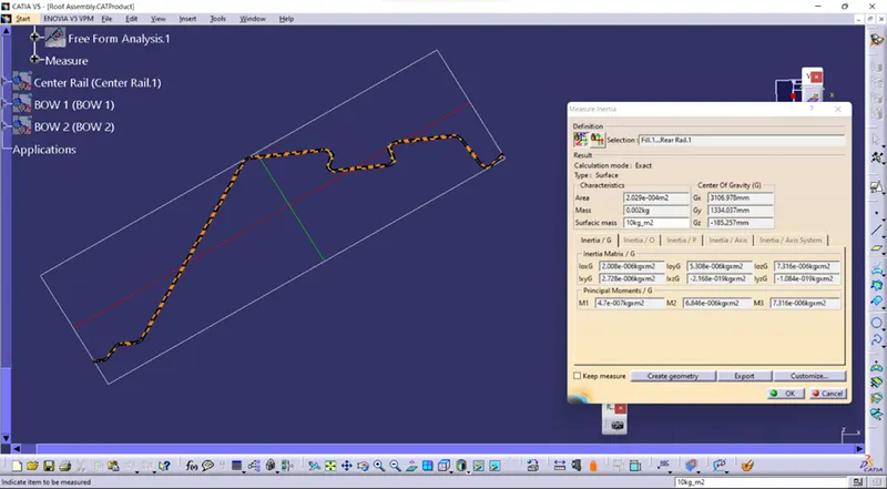
I = 4.7 X 10⁻¹mm4
Y = 201.853 / 2 = 100.9265mm
S = I / Y = 4.7 X 10⁻¹ / 100.9265
S = 46.568 X 10⁻⁴ mm3
Centre Roof Rail
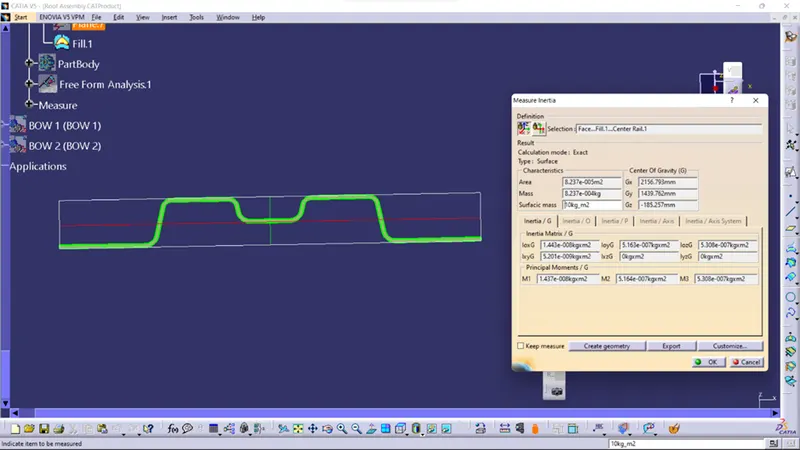
I = 1.437 X 10⁻²mm4
Y = 90 / 2 = 45
S = I / Y = 1.437 X 10⁻²/ 45
S = 31.933 X 10⁻⁵ mm3
Bow Roof Rail 1
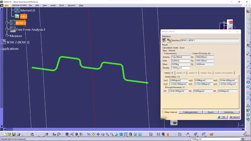
I = 3.914 X 10⁻¹mm4
Y = 75 / 2 = 37.5
S = I / Y = 3.914 X 10⁻¹/ 37.5
S = 10.437 X 10⁻³ mm3
Bow Roof Rail 2
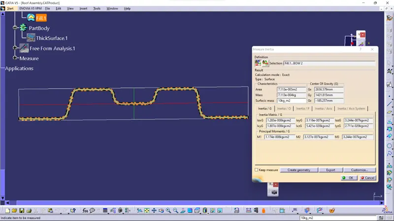
I = 1.174 X 10⁻²mm4
Y = 75 / 2 = 37.5
S = I / Y = 1.174 X 10⁻²/ 37.5
S = 31.306 X 10⁻⁵ mm3
Snow Load Prediction Formula
This calculation is done to check the strength of roof with snow load. In some country snow falls happens so for that reason this calculation is necessary,if the roof will fail in this calculation we create embosses on the roof to give strength.
Qr = [iy x t2] / [α x s x [(Rx + Ry)/2]2 x 10-8]
Where,
α = My x Lx2 x 10-12 , My = Y(Ly-Y)
t = Roof plate thickness [mm]
Ly = Distance between the front and rear roof Rails on the Vehicle along with 0Y[mm]
Length of Roof panel with the center point between Roof rail Front /Rear as the front and rear reference point.
Lx = Distance between the Left and Right end of the roof on the Roof BOW [mm]
The width of the roof panel is exposed on the surface.
Y = Distance front Front Roof Rail to Roof BOW[mm]
s = Distance for which Roof BOW bears divided load [mm]
s = L1/2 + L2/2
iy = Geometrical moment of inertia of Roof BOW (Y cross-section )[mm4]
Rx = Lateral direction curvature radius of roof panel Y cross-section on Roof BOW [mm]
Roof panel curvature Radius of the Length Lx in Front view
Ry = Longitudinal Direction curvature radius of the Roof panel X cross-section on Roof BOW [mm]
Roof panel X curvature radius of length s in Side view
Judgment condition - Qr ≥ 3.1
1) we create 2 line on the both sides of the 0Y line at 100mm distance
2) we create a middle line in between FR and BOW ROOF 1, BOW ROOF 1 and CR, CR and BOW ROOF 2, BOW ROOF 2 and RR.
3) we create 2 line on the both sides of these middle lines at 100 mm distance
4) we create intersection points of the line and project it on the roof then measure the Rx and Ry distance.
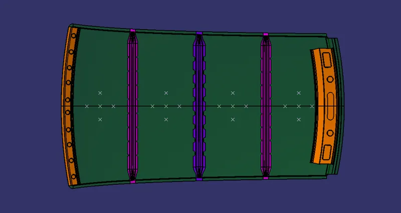

As the calculation show, This model of roof has not passed the snow load criteria.
DRAFT ANALYSIS: -
Draft Analysis allows the to easily analyse a part for proper draft angle. It was performed with 7 degree draft angle.
Roof
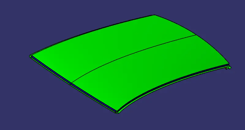
Front Roof Rail
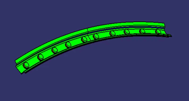
Rear Roof Rail
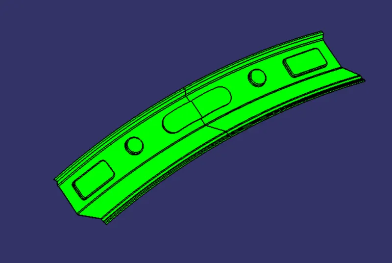
Centre Roof Rail
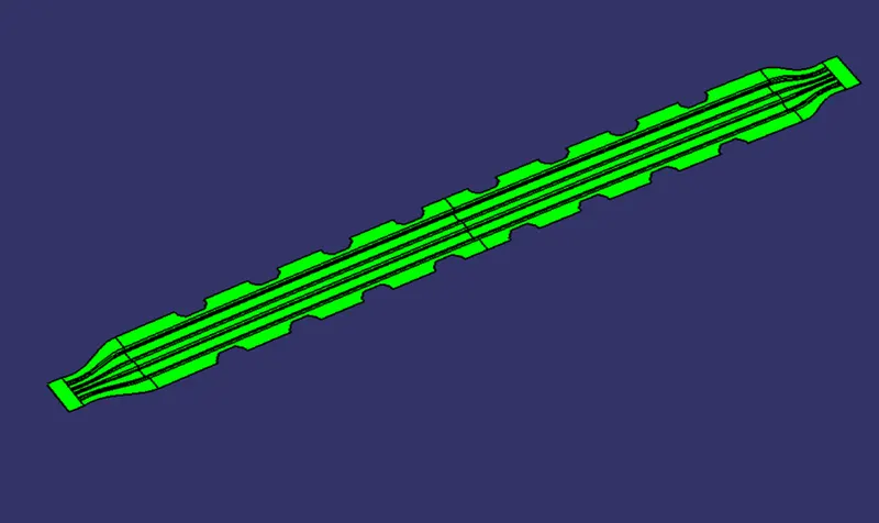
Bow Roof Rail 1
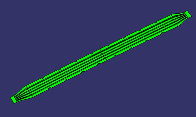
Bow roof Rail 2
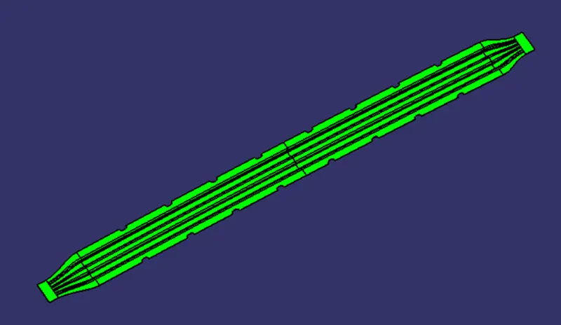
Complete Roof Assembly