Roof Design
Objective:
A dumb solid body of roof CAD model is provided for which following points to be designed and analyzed are as follow,
- Extracting the styling surface and for the given car roof styling and design the essential flanges and reinforcement, namely Ditch Area, Front Roof Rail, Rear Roof Rail, Centre Roof Rail, and Bow-Roofs.
- Do a curvature study on the roof and perform calculations for Heat Distortion and Snow load criterion to determine and justify the position of the Bow-roofs.
- Finding a moment of inertia and Section Modulus for Bow Roof Rails and Centre Roof Rail.
- Perform a Draft Analysis of each reinforcement.
What is Roof :
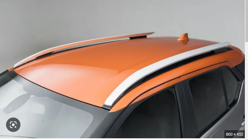
An automobile roof is the or portion of an automobile that fit or located on above the passenger compartment, it is protecting the vehicle occupants from sun, wind, rain, and other external particles. In under the roof we can see there are many other structures under the roof those are give strength and stability to the roof.
There are number of reinforcement structures/supports different size of the vehicle. They are installed on flat surface of the roof to increase the strength of roof.
Reinforcements :
Here we give some structurels to the bottom side of the roof ,
There are the Front Roof Rail, Rear Roof Rail, Centre Roof Rail, and Bow Roof Design which are given Mastics and spot-welded to roof flanges & ditch areas and improve NVH(Noice , Vibration & Harness) value by increasing the strength of the roof using mastic sealants.
Mastic sealants apply for all members.
Design consideration of roof:
- Visibility Criteria
- Head clearance
- Curvature study
- Heat distortion and snow load criteria
- Draft analysis.
- Safety parameters
Roof Crush Test for Car:
Here we should conduct the some crash test to roof of the vihicle for safety purpose, Safety point of view vehicle roof is very important part , when the car will get accident it will roll and it will det deformation, And when vehicle rollover crashes in that time that will make injury to passenger head, neck, and passenger will lost his life aslo.
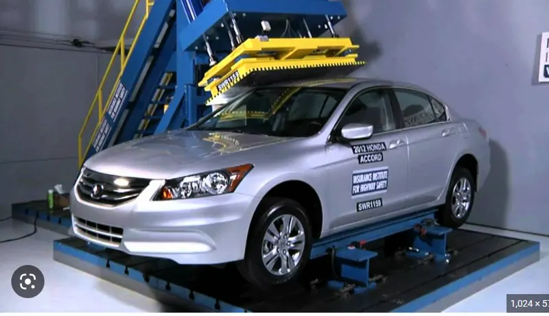
Therefore, passenger safety is also a very important parameter in every vehicle , we can design and manufature the high efficiency and high milleage vehicles by decreasing the wight of the vehicle it means maintain the lower gauge thick sheet in BIW but when the vehicle goes uder accident it will get more fracture or damage quickely and This can cause injury to passengers and they may even lose their lives also. So for every passenger vehicle we should do the Crash Test. And this is stipulated by international standards that are now placed in several countries, as well as a governmental requirement. For this reason, strength and safety is a very important criterion for designing a vehicle roof.
This design is been given by the institute of highway safety after anaysing so many accidents are which happen . After the fixed some regulation how to perform this test & they also given the regulation and they give rating how to fast the car reponse to the original condition or how deep the protrusion after the colhesion.
But The very important test for the Roof is Roll-Over test.
Condition of the Test :
For this test we take only the BIW or Outer body of the car.
* Close & lock the all doors.
* Close the windows.
* Car is placed on Horizantal surface.
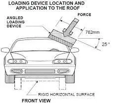
* Applying Load is 22040 N. This load is act on the Roof from the out side at almost 120 sec at 5° angle from the front & 25° from the Side of the CAR.
* The Load will be act 1800 mm in roof lenght & 750 mm in its width.
* The speed of the load applied is almost 13 mm/sec
The strength of the roof structure to occupant protection in real-world rollover crashes, requiring the maximum moving distance of the roof structure should be less than 127 mm (5 in.) when the induced load is 1.5 times the vehicle weight.
The displacement of the load application device is 127mm or less when load of 1.5 times the unloaded vehicle weight is 22.240 N is applied.
This test can be conducted on either side of the roof structure, the front left or the front right side but not on both sides in one single test and still meet the requirements of the test. .
Also, the direction of the force shall be downward and perpendicular to the lower surface of the rigid plate and such that it moves in a straight line without rotation. The duration of the test shall not exceed 120 seconds. The longitudinal axis of the plate is pitched forward at a 5 º angle as viewed from the side of the passenger car as shown in below fig..,
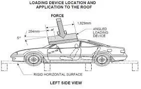
The lateral axis or the roll of the plate is such that it forms a 25 º outboard angle with a horizontal surface as viewed from the front of the passenger car as shown in below fig..,
Design Methodology:
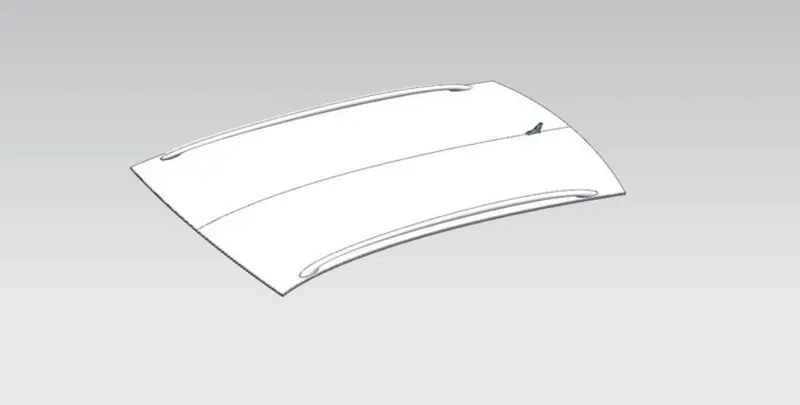
Roof Outer Panel : Here intially we have styling surface, This styling surface is provided from the styling team, from this surface we extract the required reinforcements like Ditch area, Front Roof Rail, Bow Roof Rails,Centre Roof and Rear Doof Rail.
Styling surface :
Design a Ditch Area for Outer Roof Panel:
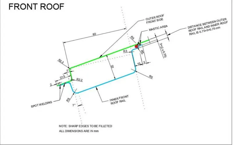
Here Styling team provided the master section for the roof ditch area, front roof rail and rear roof rail as per the design parameter of visibility criteria, head room clearance and other important parameter dimension like of windshield, sealant rubber etc . Here designing is done just to replicate those input data considering engineering parameters which should be feasible for manufacturing. Master section of front and rear section.
1. Front Ditch Area:
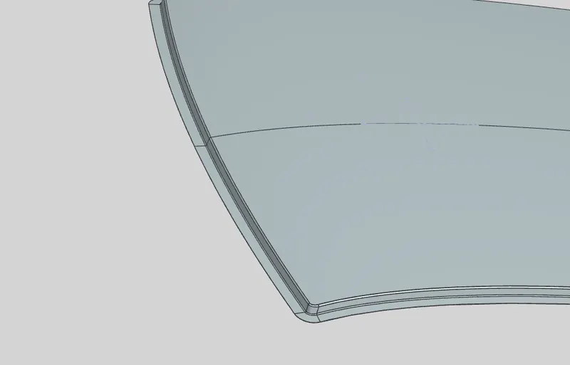
Here from given styling surface the class A surface is extracted and ditch area are designed considering the as per given following master section.
Flange of around 21.5mm created with the law extension command, corner relief at rear flanges and positive draft 7 degree considering for the deep drawing operation process. Overall thickness of sheet metal consider 0.75mm throughout.
2. Rear Ditch Area:
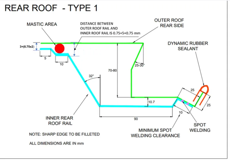
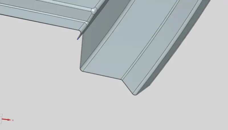
Here Surface is offset from the outer panel to form the ditch area and with the law extension command, corner relief at rear flanges and positive draft (7 °) in required degree considering for the drawing operation process. Overall thickness of sheet metal for outer panel consider 0.75mm throughout.
Roof Panel with Front and Rear Ditch Area 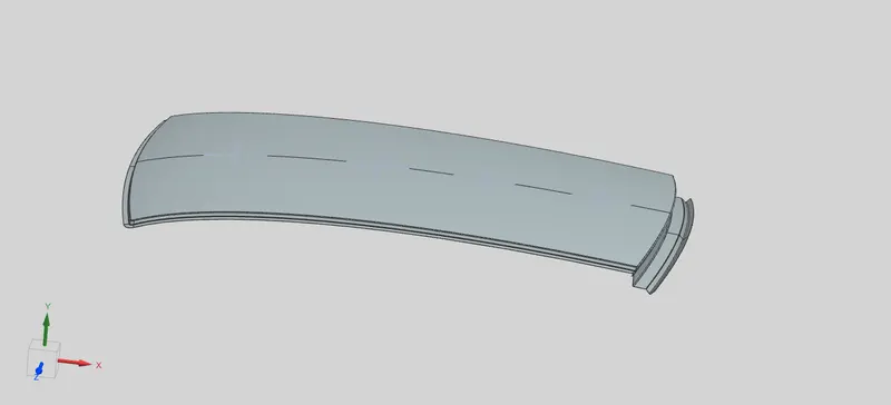
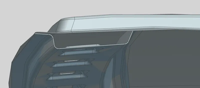
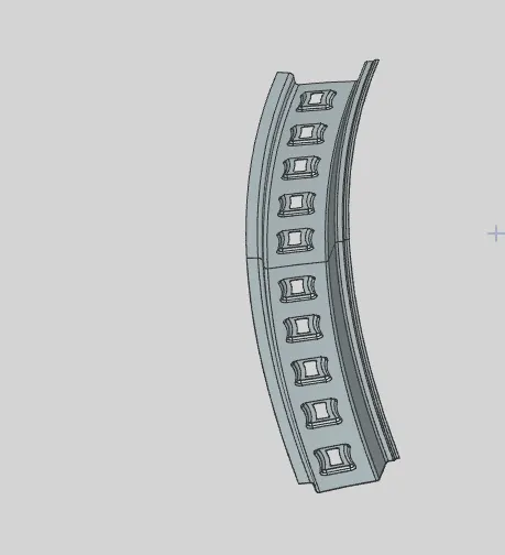
Front Roof Rail:
It is the additional commadity which is been given as reinforcement & also has certain features in it ehich will be supportingthe room lamp which is been mounted on this Rail.
The front roof rail is placed on the front of the car and it is give the support to the roof front area.This element is fixing with roof by help os spotwelding and mastic sealants.
The front roof rail is placed at front of the vehicle and it is connecting with A-Piller.
Here we maintained the Sheet Thickness is 0.75 mm
Draft angle is 7° possitive draft.
Here we maintain the some design consideration visible creteria up to 32 mm and head room clearence up to 83 mm.
Rear Roof Rail:
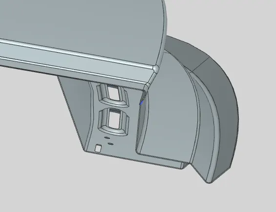
The rear roof rail is give the support to the rear end of the roof and it is give more strenght to the roof . It is joined to the back door and the body side outer and inner panel. Here we maitained the thickness of it is 0.75 mm and possitive draft angle is 7°. we have to take into consideration the rear Headroom Clearance and the rear visibility criteria while designing the Rear Roof Rail. All dimensions are taken from the rear master section shown in fig.
Here following design consideration are mentioned.
Headroom clearance: 85 to 120mm minimum and this is changed upon projects to project & also region to region.
Sheet metal thickness: T= 0.75mm
Radius: (R=3mm and 5mmm ): R+T
Draft angle : 7°
Emboss hieght : 3 to 4 mm
Emboss Draft : 10°
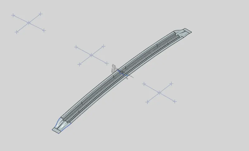
Bow Roof 1:
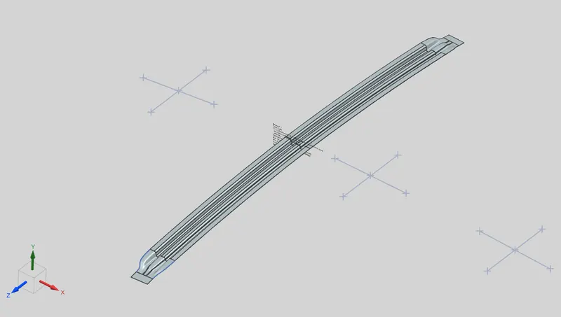
Bow roofs are given to improve the strenght of the roof and its give support and stiffness to the roof and it will make roof to withstand the external load. The number of bow roofs provided will be depend upon the overall length of the roof. In longer roof we have to inserted more bow roof and they are attached to the roof inside by using mastics selants. The each mastics pointss are has Min 80 mm Circular effective area.
And all these bow roof positioning is decided based on curvature study and here we should check or perform the Heat distortion criteria and snow load criteria.
These criteria are analysys the position of the bow roofs in various condition.
The thickness of the Bow Roof : 0.75mm
Draft : 7°
Bow Roof 2:
Bow roofs are given to improve the strenght of the roof and its give support and stiffness to the roof and it will make roof to withstand the external load. The number of bow roofs provided will be depend upon the overall length of the roof.
Centre Roof Rail:
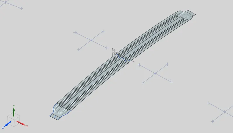
Centre roof rail is provided to give more support to the flat area of the roof and it is more usefull for withstand the load , the centre reinforcement roof rail will be placed at the centre of the roof connecting the B pillar.
B piller is give support to the Cemter roof and it will protect the passenger while car get accedent and roll-over test also done with this.
The thickness of the centre bow roof is 0.75 mm thickness. and draft and radius parameters are same as per the other roof rail
Mastic Sealants:
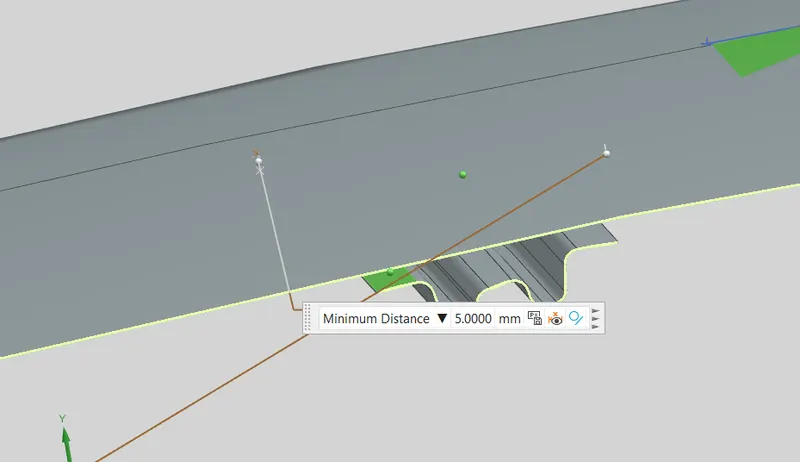
It is addesive and Bow Roof Rails and Centre Roof Rail are joined with the help of Mastic Sealant. Here we cant's use the Spot welding because it damages the A class area of the Roof. So, the mastic sealant is used in this area.
Here we have to give 5 mm clearence between to all bow Roofs to Roof inside surface .
And mastics has 80 mm Circuler effective area .
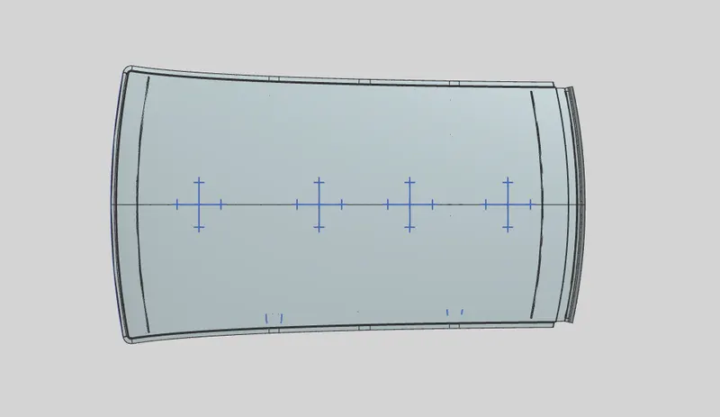
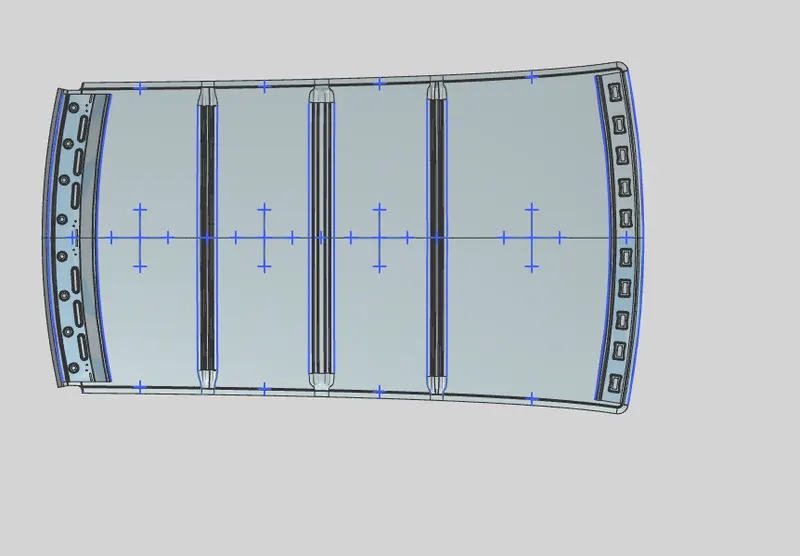
Roof Top View:
Bottom View:
Heat distortion study :
The heat distortion study plays an important role in sheet metal usage. Heat distortion temperature is a temperature limit above which the material cannot be used for structural applications. This study is used to predict the heat distortion temperature at where the material starts to sofen when exposed to a fixed load at elevated temperature. In order to avoid bending or damages on roof, based on heat distortion temperature, this study will predict the bow roof position on the roof to strengthen the roof.
Bow–Roof Prediction Formula
W = [1.73 x 10^(-3) x L] + [1.85 x 10^(-8) x (R^2)/t] + [ 1.10x10^(-3) x l] - 2.68
Where,
L = Roof Length in X-Direction[mm](Roof dimension in 0-Y)
R = Roof curvature
R = 2(Rx*Ry)/(Rx+Ry)
Rx = X curvature
Ry = Y curvature
t = Roof plate thickness [mm]
l = Bow Roof Span [mm]
Judgment Condition
OK< 2.7
Here i mentioned the all parameters of Roof.
Thickness for the Roof:
Roof Outer Panel, t = 0.75 mm
Front Roof Rail, t = 0.75 mm
Bow Roof Rail, t = 0.75 mm
Centre Roof Rail, t =0.75 mm
Bow Roof Rail 2, t = 0.75 mm
Rear Roof Rail, t = 0.75 mm
Here i maintained same thickness for all structures.
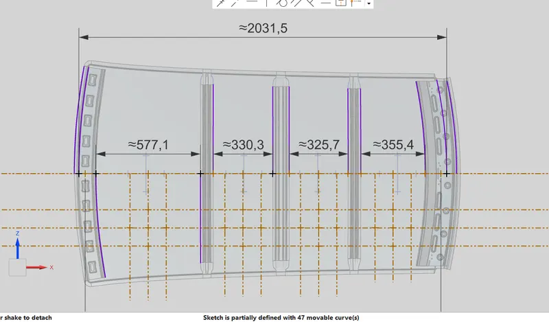
Roof Length for styling Surface (L) :
Here we have to consider the total lenght (L) of styling surface rest of ditch area.
Bow Roof Span (l):
Here want to take the distance from the Front Roof Rail to Bow Roof 1 to find the Bow Roof Span as shown in fig. remaining all the span distance also want to measure. Here i measured distance between each Bow roof rails
Curvature Study on the Roof:
Rx & Ry (X & Y Curvature):
Rx & Ry are the curvature of the roof , Rx is represent along roof width and Ry is represent along roof lenth in between two adjucent roof rails .
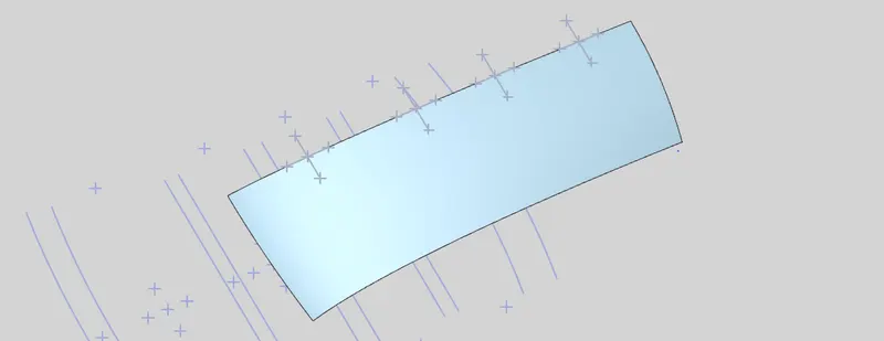
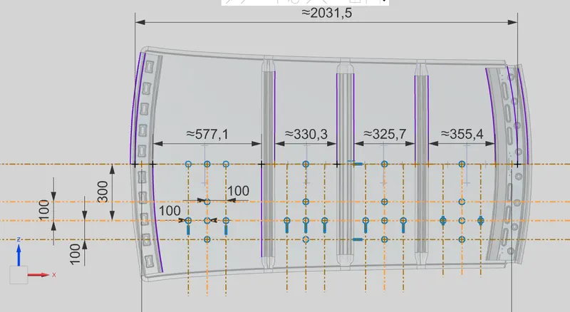
Here we have to drawn offset the axis at 300 mm From the Y-0 axis as shown in the bellow figure, then again offset the drawn line at 100 mm on both side. Then create the centre point b/w Front roof rail and Bow roof rail 1. drawn a line perpendicular to the Y-0 Axis by using creted point then offset it 100mm on both side as shown in below image.
Then create the intersection point for each lines as shown in below image.
Project the intersection points in the sketch to roof surface as shown in fig.
Join the projected curves using arc curve and measure the minimum radius and linear dimension as follow & put into the formula to calculate “W” .
From the above fig, now project the points on the top of the Roof and draw the arc with the three points intersecting area as shown in below fig
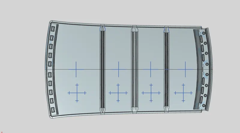
* Find the Rx Curvature and Ry Curvature withe the tool Simple Radius or local radius command. For example shown in fig below
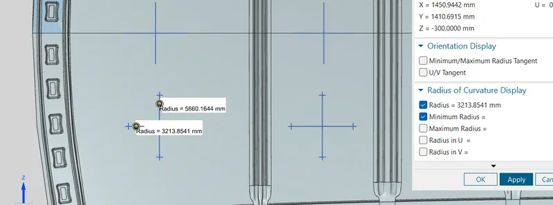
Apply the values in the formula:
To find the Heat distortion apply all the necessary values from the Roof to the given formula.
Heat Distortion Criteria Calculations:
W = [1.73 x 10^(-3) x L] + [1.85 x 10^(-8) x (R^2)/t] + [ 1.10x10^(-3) x l] - 2.68
R = 2(Rx*Ry)/(Rx+Ry)
Table and Calculations are Performed in MS Excel:

From the above table it can be concluded that all values of W< 2.7
This value is clear the our bow roof positioning is good . Now we can go with next step.
Snow Load criteria
Snow load criteria study is done to check the durability of the roof to withstand snowfall and reflex back to its original shape without any permanent deformation once the load is removed.
Snow Load Prediction Formula
Qr = [Iy x t2] / [α x s x [(Rx + Ry)/2]2 x 10-8]
Note: The Qr value given over here is correct. There was a typo error in the formula given in the video.
Where,
α = My x Lx2 x 10-12 , My = Y(Ly-Y)
t = Roof plate thickness [mm]
Ly = Distance between the front and rear roof Rails on the Vehicle along with 0Y[mm]
Length of Roof panel with the center point between Roof rail Front /Rear as the front and rear reference point.
Lx = Distance between the Left and Right end of the roof on the Roof BOW [mm]
The width of the roof panel is exposed on the surface.
Y = Distance front Front Roof Rail to Roof BOW[mm]
s = Distance for which Roof BOW bears divided load [mm]
s = L1/2 + L2/2
Iy = Geometrical moment of inertia of Roof BOW (Y cross-section )[mm4]
Rx = Lateral direction curvature radius of roof panel Y cross-section on Roof BOW [mm]
Roof panel curvature Radius of the Length Lx in Front view
Ry = Longitudinal Direction curvature radius of the Roof panel X cross-section on Roof BOW [mm]
Roof panel X curvature radius of length s in Side view
Judgment condition
Qr ≥ 3.1
250 ≤ s ≤ 380
Rx & Ry (X & Y Curvature):
Inthis caluclation intially we have to create center line on the roof along its length by using sketch then offset it upto 100 mm on both side. One more line we have to create in between the Front Roof Rail and Bow roof as shown in the below images and that also mirror at 100 mm on both side.
Ofter this use the intersection point to create the points to required position.
Here we take the L1 and L2 dimension from two adjucent roof rails .
Then project the points on the Roof surface and use Three point arc command for create the curve onthe roof through Points which are projected.
Then measure the curve by using measuring or local raduis command to caluclate the values
Put all the linear and radial dimension in following formula to calculate Qr Value.
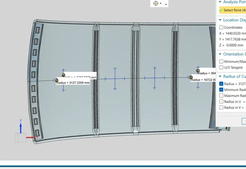
Here WeFind the Lx and Ly values take the styling surface of the roof and all dimensions.
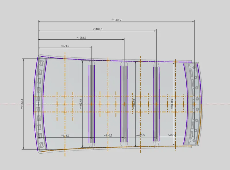
Moment of Inertia for the Roof Rails:
MOI of Bow Roof 1 :
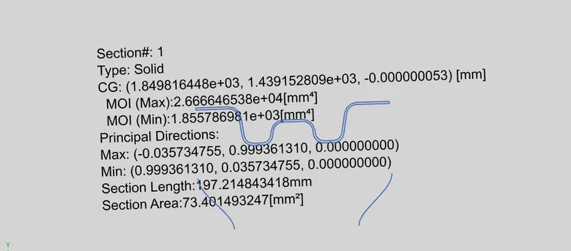
MOI of Centre Roof Rail:
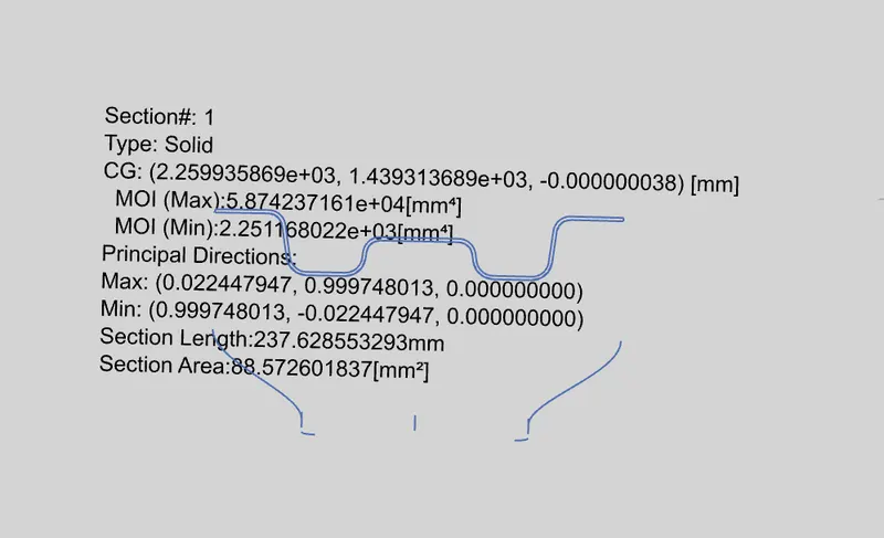
MOI of Bow Roof 2 :
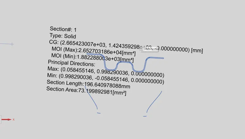
Apply the values in the formula :
To find the Snow load apply all the necessary values from the Roof to the given formula.
Snow Load Prediction Formula:
Qr = [Iy x t2] / [α x s x [(Rx + Ry)/2]2 x 10-8]
where,
α = My x Lx2 x 10-12 , My = Y(Ly-Y)
s = L1/2 + L2/2
Table and Calculations are Performed in MS Excel:

Judgment condition
Qr ≥ 3.1
Here Qr values are above the Judgment condition , so it is ready for the Production.
Draft Analysis:
The Draft Analysis command enables you to detect if the part you drafted will be easily removed. This type of analysis is performed based on colour ranges identifying zones on the analysed element where the deviation from the draft direction at any point, corresponds to specified values.
Minimum draft angle of 7° is considered for analysis . Green colour infer on the parts that that all face along the tooling direction has positive draft angle greater than 7° and passed in analysis.
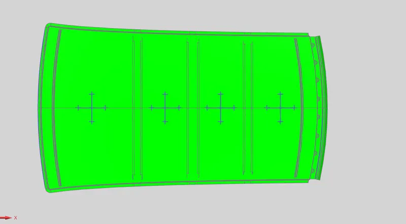
Roof Outer Panel

Front Roof Rail
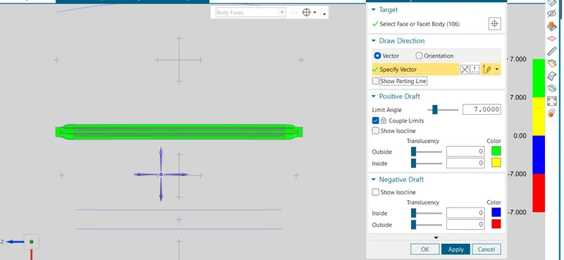
Bow Roof 1
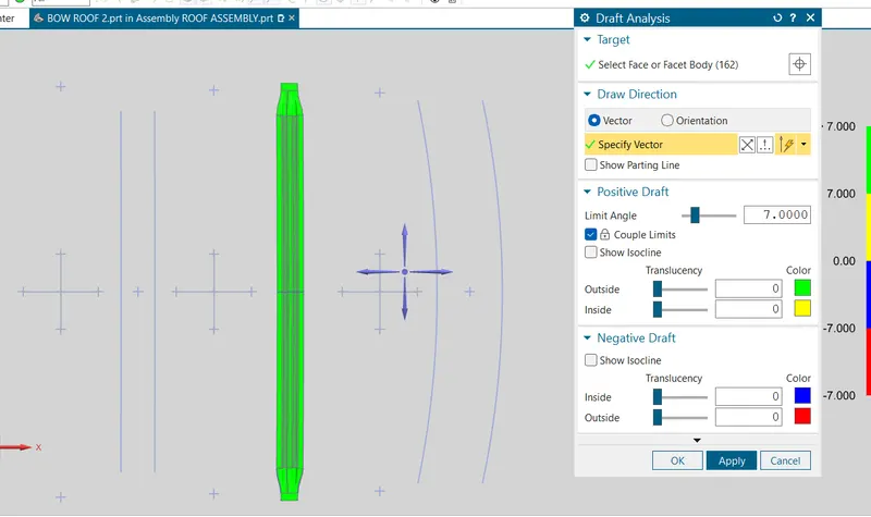
Bow Roof 2
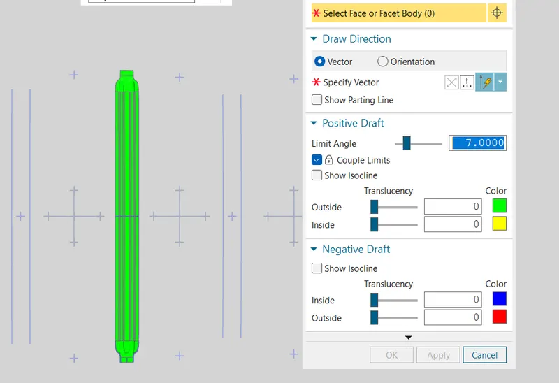
Centre Roof Rail
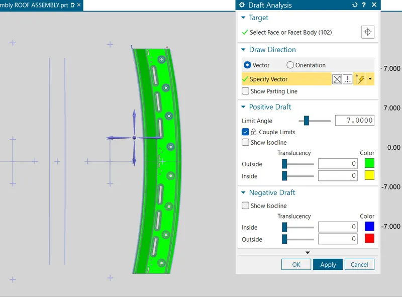
Rear Roof Rail
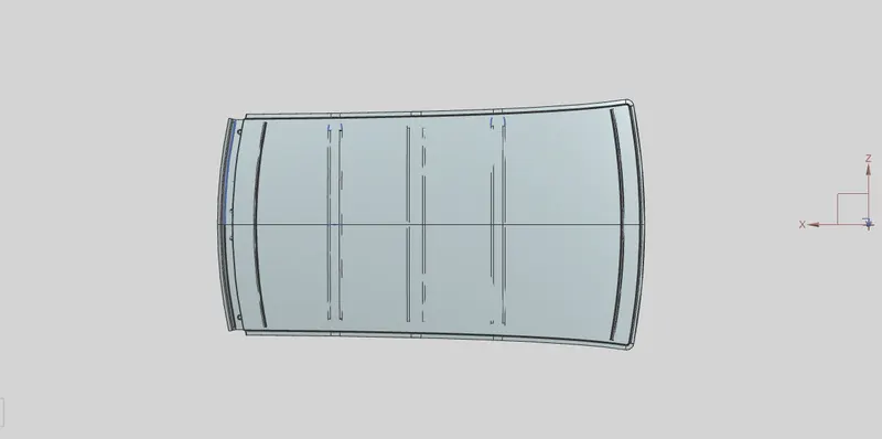
Roof Model Views:
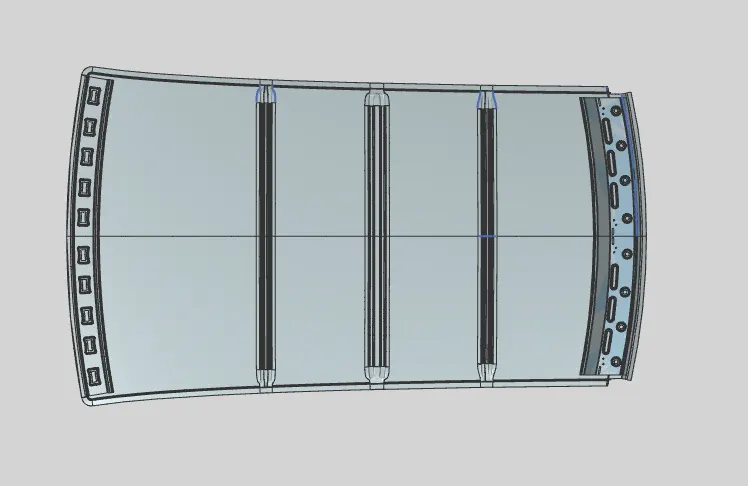
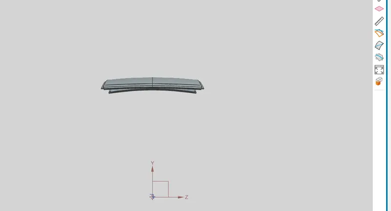
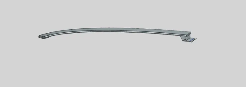
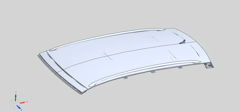
MANUFACTURING METHOD :
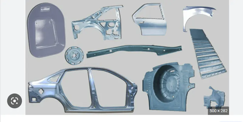
In automobile industry they maufacture the BIW parts from Stamping method or process.
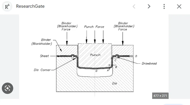
What is Stamping process in sheet metal?
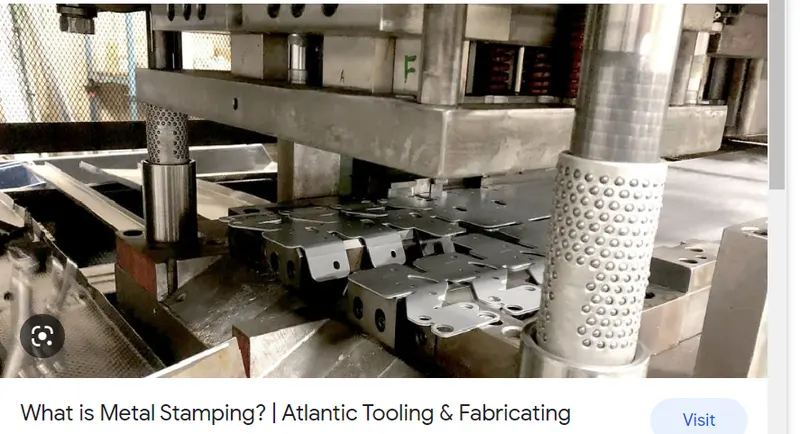
The process of turning sheets of metal into a useful part or component is called sheet metal stamping. The metal is fed into a press, where the stamping tool, also known as a die, creates the desired shape. The die is pressed into or through the metal with tremendous force. As show in below images.
Conclusion:
The Design of Roof, Front roof rail, Rear Roof Rail, Bow Roofs, and reinforcement roof center are designed is with the design parameters for the given master section.
- All reinforcement BIW parts of roof are designed according to the input data provided by the styling team. Designed parts will be submitted to CAE (Computer Added Engineering) team to carry out further FEM (Front -End-MOdule)analysis to obtain numerical data to improve the design.
- Made the curvature study and analysis the design for Heat distortion are values are OK.
- Made the curvature study and analysis the design for Snow Load are values are OK. But
* Also we can provide emboss in the roof show in the below fig. The Embosses are increased the strength of the roof.
- Moment of inertia and Draft analysis are carried out to check the feasibility of manufacturing are done.