Roof Design
ROOF DESIGN
AIM: to design a roof with the reinforcement components like front roof rail, rear roof rail, centre roof rail and two bow roofs.
OBJECTIVE
1.To design a roof of the car with the given styling surface.
2.perform the curvature study.
3.calculate the heat distortion and slow load criteria.
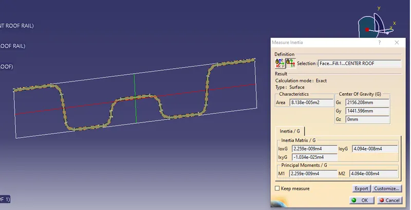
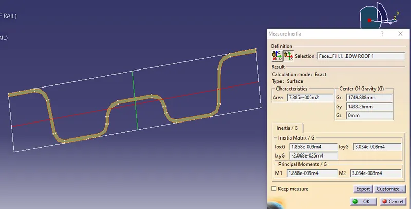
4.calculate the moment of inertia of the reinforcements.
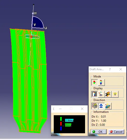
5.perform the draft analysis of the reinforcements.
ROOF
Roof is a top portion of the car that sits above the passenger compartment,protects the passengers from sunrays, wind,rain,dust and other particles hitting the passengers.
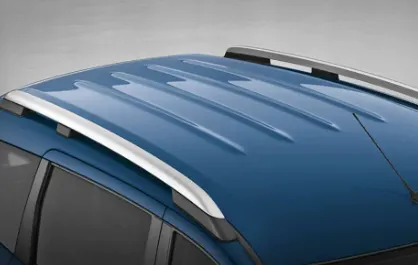
Types of car roofs
1.hard tops
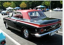
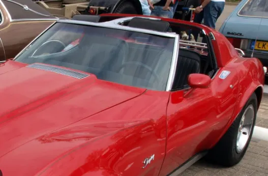
2.T-tops
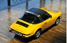
3.Targa tops
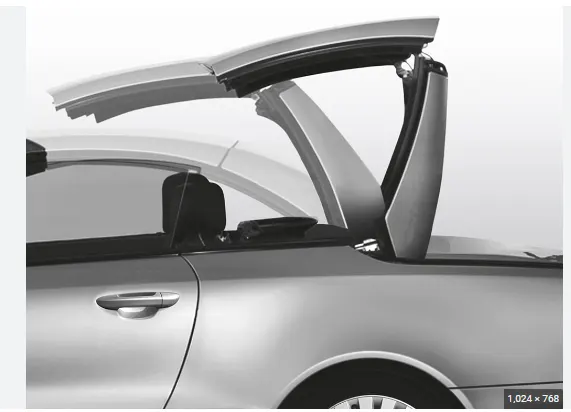
4.convertible roofs
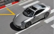
5.Sun roofs
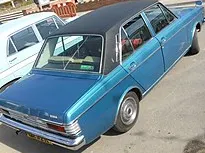
6.Vinyl roofs
Design considerations of roof
1.Curvature study
2.Head clearance
3.visibility criteria
4.safety parametres
5.heat distortion and snow load criteria
6.draft analysis
Crush test for passenger car roof
The strength of the roof plays a very crucial role in the safety of the passengers whenever the vehicle rolls over onto its side of the roof,roof rollover crash is the cause of many fatalities to the head, neck and spine injury.
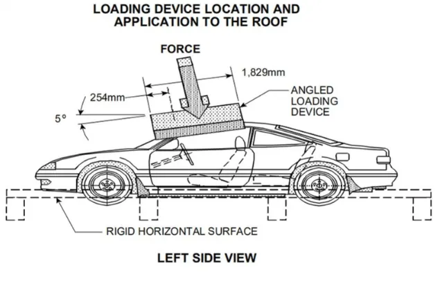
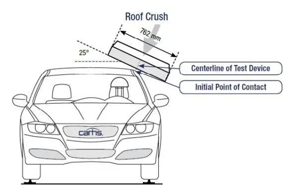
The test is conducted on a BIW car roof rigidly placed on a horizontal surface with the doors and the windows closed.
further a flat rigid block with the given dimensions as shown in the below figure is advanced towards the roof for 120 seconds with a crushing speed of 13 mm per second or less and the deformation of the roof is studied.
The loading Block is tilted 5° to the forward as viewed from the side.
INPUTS
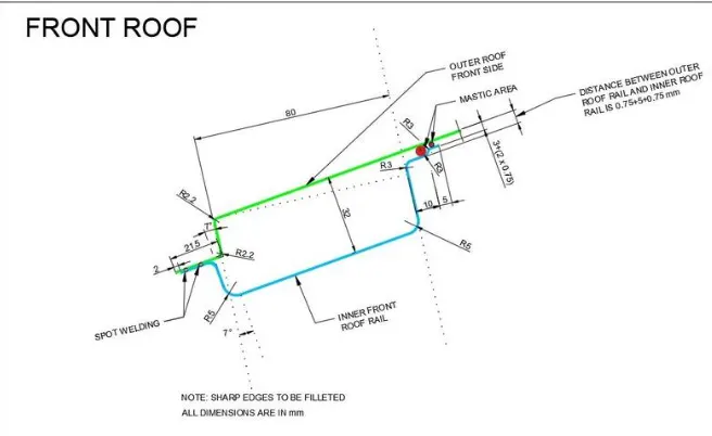
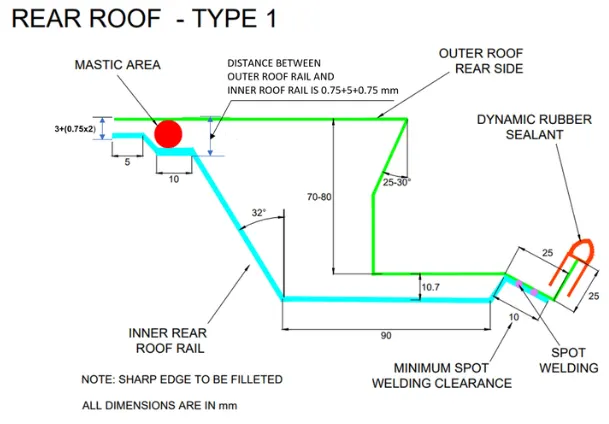
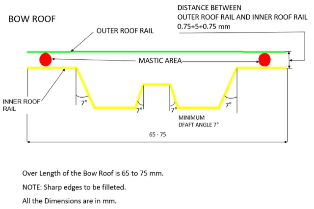
Master sections of the reinforcements like front roof, rear roof, Centre roof, Bow roof are provided.
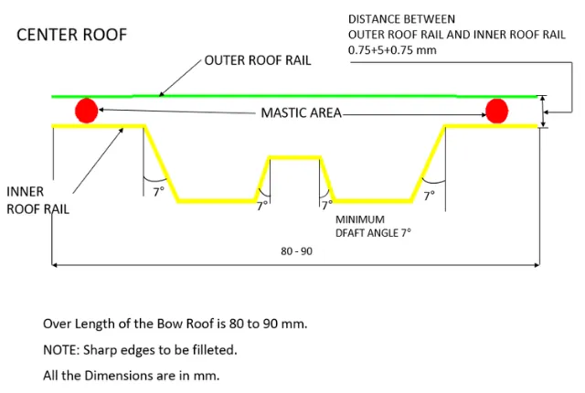
Styling surface of the car roof
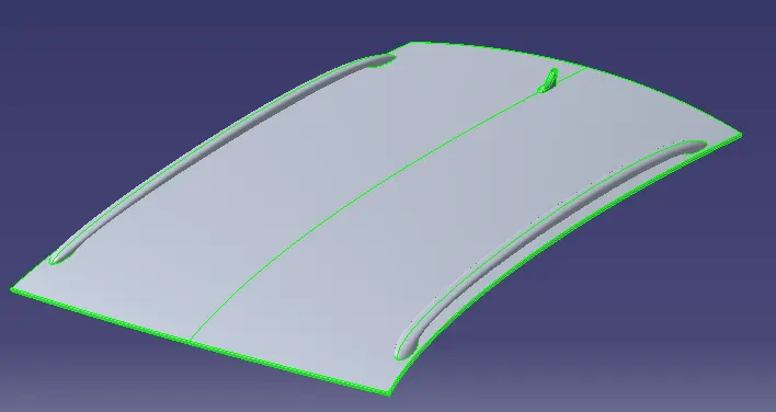
Design methodology for the ditch area
The ditch area is the extended portion of the roof which is joined by BIW components and other aesthetic surface.It serves as the joining process for the reinforcements which are joined by spotwelding.
The ditch area are designed by the given master section in the front roof rail and rear roof rail.
below is the image showing the ditch area for the front section of the roof.
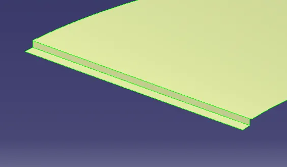
Ditch area for the rear section of the roof
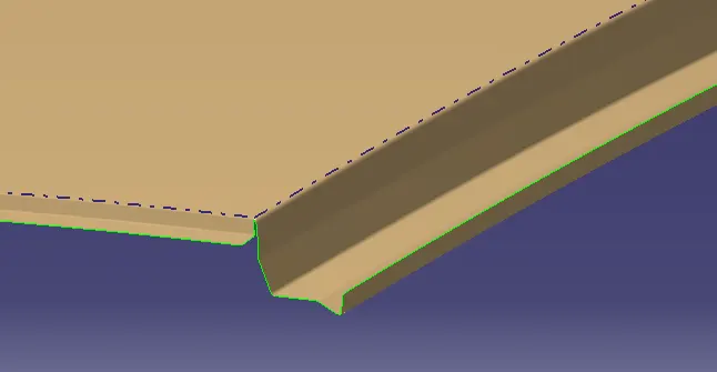
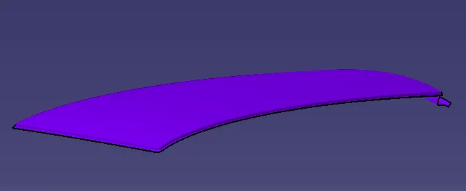
Roof image after ditch design
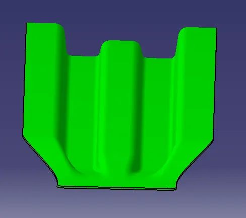
Front roof rail
Front roof rail is the link between the roof, windshield glass and head liner. The visibility criteria and headroom space are the factors considered while preparing the master section of the front roof rail.
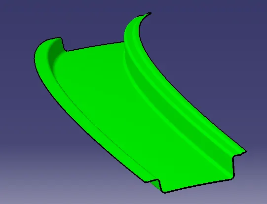
Rear roof rail
rear roof rail is connected to the backdoor and plays a vital role in the movement of the back door rotation.
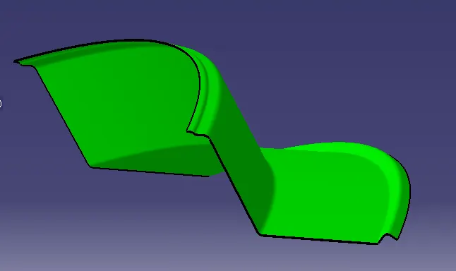
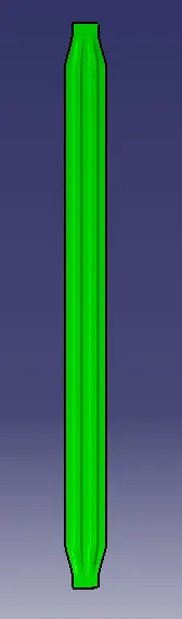
Centre roof and Bow roof
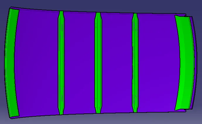
Final image of placement of reinforcements
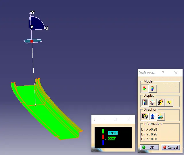
Draft Analysis of Front roof rail
Draft analysis of rear roof rail
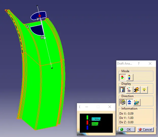
Draft analysis of Center roof
HEAT DISTORTION CALCULATION
The formula for the heat distortion calculation is given below
W = [1.73 x 10^(-3) x L] + [1.85 x 10^(-8) x (R^2)/t] + [ 1.10x10^(-3) x l] - 2.68
Where,
L = Roof Length in X-Direction[mm](Roof dimension in 0-Y)
R = Roof curvature
R = 2(Rx*Ry)/(Rx+Ry)
Rx = X curvature
Ry = Y curvature
t = Roof plate thickness [mm]
l = Bow Roof Span [mm]
Judgment Condition
OK< 2.7
The above values are measured and the Heat distortion calculation is done and shown below in the table.
|
SL No. |
ROW | Rx | Ry | R | I | L | t | (R*R)/t | W |
| 1 | FR & BR1 |
5713.835 |
2880.272 | 3829.926 | 481.503 | 2033.704 | 0.75 | 19557777.55 | 1.729 |
| 2 | BR1 & CR | 4857.087 | 6590.666 | 5592.615 | 331.879 | 2033.704 | 0.75 | 41703123.38 | 1.974 |
| 3 | CR & BR2 | 4070.619 | 10511.069 | 5868.532 | 331.901 | 2033.704 | 0.75 | 45919557.11 | 2.0529 |
| 4 | BR2 & RR | 3351.883 | 15744.597 | 5527.096 | 453.949 | 2033.704 | 0.75 | 40731720.26 | 2.0911 |
From the above table it is found that the reinforcement placements are optimum and follow the design criteria for heat distortion.
SNOW LOAD CALCULATION
formula for the snow load calculation is given below
Qr = [Iy x t2] / [α x s x [(Rx + Ry)/2]2 x 10-8]
Where,
α = My x Lx2 x 10-12 , My = Y(Ly-Y)
t = Roof plate thickness [mm]
Ly = Distance between the front and rear roof Rails on the Vehicle along with 0Y[mm]
Length of Roof panel with the center point between Roof rail Front /Rear as the front and rear reference point.
Lx = Distance between the Left and Right end of the roof on the Roof BOW [mm]
The width of the roof panel is exposed on the surface.
Y = Distance front Front Roof Rail to Roof BOW[mm]
s = Distance for which Roof BOW bears divided load [mm]
s = L1/2 + L2/2
Iy = Geometrical moment of inertia of Roof BOW (Y cross-section )[mm4]
Rx = Lateral direction curvature radius of roof panel Y cross-section on Roof BOW [mm]
Roof panel curvature Radius of the Length Lx in Front view
Ry = Longitudinal Direction curvature radius of the Roof panel X cross-section on Roof BOW [mm]
Roof panel X curvature radius of length s in Side view
Judgment condition
Qr ≥ 3.1
250 ≤ s ≤ 380
CALCULATING MOMENT OF INERTIA
MOMENT OF INERTIA OF CENTER ROOF
MOMENT OF INERTIA OF BOW ROOF 1
MOMENT OF INERTIA OF BOW ROOF 2
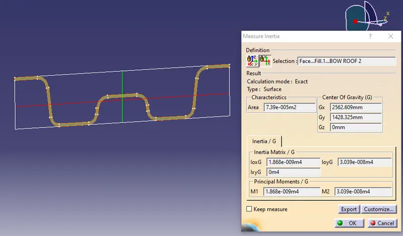
The above values are measured and tabulated and snow load calculation is performed.
| SL No. | ROW | Rx | Ry | Lx | Y | My | α | S | Iy | Qr |
| 1 | FR & BR1 | 4351.659 | 2880.269 | 1134.491 | 570.909 | 835122.8 | 1.074 | 489.297 | 1858 | 15.21 |
| 2 | BR1 & CR | 3788.458 | 6523.25 | 1086.837 | 978.594 | 1032524 | 10219 | 407.286 | 2259 | 9.622 |
| 3 | CR & BR2 | 4228.453 | 10511.07 | 1063.919 | 1385.482 | 898099.9 | 1.016 | 488.128 | 1868 | 3.9 |
| 4 | BR2 & RR | 1954.851 | 154145.9 | 226.974 |
From the above table it is found that the design follows the snowload criteria