Roof Design
Roof:
An automobile roof or car top is the portion of an automobile that sits above the passenger compartment, protecting the vehicle occupants from sun, wind, rain, and other external elements. Because the earliest automobiles were designed in an era of horse-Drawn carriages, early automobile roofs used similar materials and designs.
Types of Roofs are;
- Convertable Roof
- Hard top
- Sun Roofs
- T Tops
- Targa Tops
- Vinyl Roofs
Objective:
To design a car roof with its component by following the master section of the front rail (front row, bow roofs, centre roof rail and rear roof rail) with all the design parameter. And also, analysis the snow load and heat distortion. Heat and snow load formulas are gives in industry standard
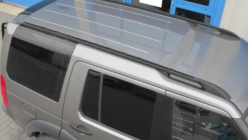
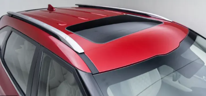
ROOF CRUSH TEST :
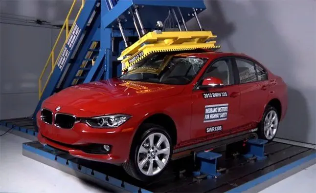
Roof crush test is the design given by the IIHS ( insurance institute of highway safety ) . After analyzing the many accidents IIHS has then fixed some regulations , that how to perform the crush test .
IIHS gives the rating based up on this test . For this they consider two points while giving the rating
- How fast the car can reforms to its original shape after the roll over and
- How deep is the protrusion after the roll over
METHOD OF APPLYING THE FORCE :
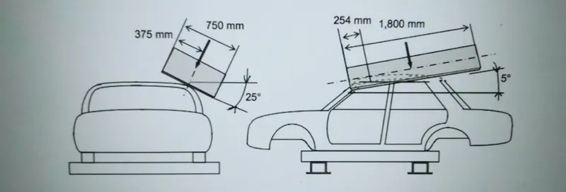
The load is applied in such a way that 50 is tilted from the front end to the rear end and the load will be in 1800 mm in length and 750 mm in width . The load is applied at the position of 250 from the flatness of the roof . The load is applied on the roof for almost 120 sec and the crush speed at which the load applied is 13 mm/sec or less than that
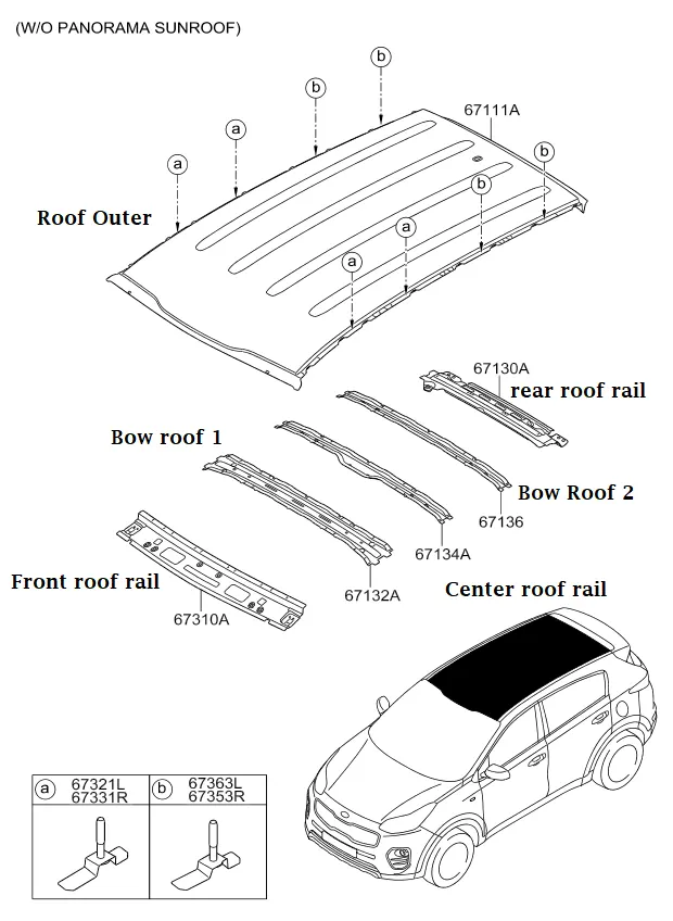
Roof contains Different sunparts, They are
1) Roof Outer
2) Front Roof Rail
3)Bow Roof Rail 1
4) Centre Roof Rail
5) Bow Roof Rail 2
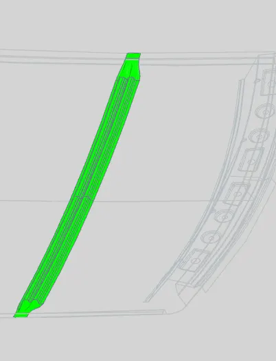
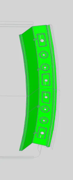
6) Rear Roof Rail
Manufacturing Process;
Stamping and Cutting Operations
Stamping Process: Stamping or pressing is a manufacturing process used to convert flat metal sheets into final shapes. In this process, a flat sheet of metal, either in the form of a blank or in the form of a coil, is placed in a stamping press where a tool and die surface forms the metal into a final shape.
Stamping encompasses a variety of sheet metal forming manufacturing processes, such as punching using a machine press or stamping press, blanking, embossing, bending, flanging, and coining.
Types of Stamping operations are:
- Drawing – the surface area of a blank is stretched into an alternate shape via controlled material flow. See also deep drawing.
- Bending – the material is deformed or bent along a straight line.
- Flanging – the material is bent along a curved line.
- Embossing – the material is stretched into a shallow depression. Used primarily for adding decorative patterns
Cutting Operations : Trimming is a process in which the outer perimeter of a formed or flat part is cut away to give the piece part its finished or partially finished profile. The excess material, commonly called addendum or offal, often is recovered, collected, and resold as scrap
Piercing:It is a shearing process where a punch and die are used to create a hole in sheet metal or a plate. The process and machinery are usually the same as that used in blanking, except that the piece being punched out is scrap in the piercing process.
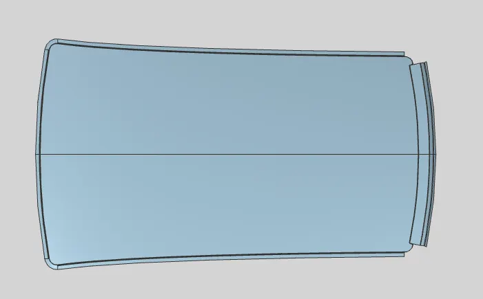
Roof Outer Panel:
Given Mastersections are
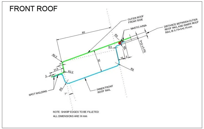
1) This Front Roof Rail locates at front end of Roof Outer panel
2) Front Roof supports the windshield glass and attached with Roof outer and Body
3) Mainly Visibility Criteria need to check.

Bow roof Rail:
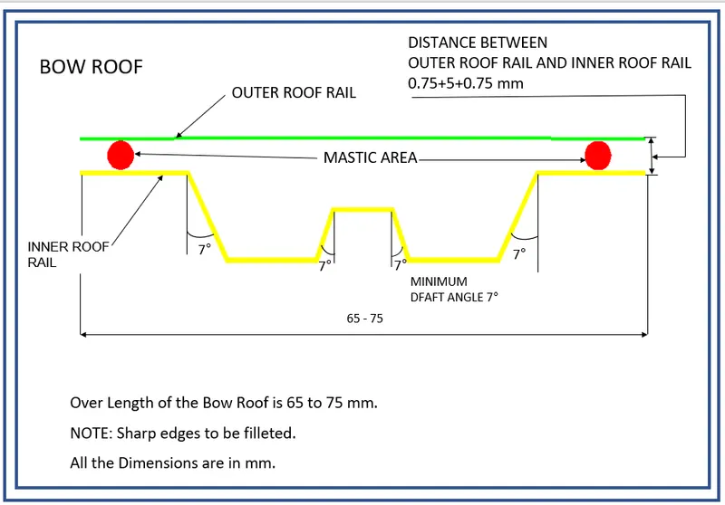
Bow Roof RAil 1
1) This Bow Roof rail1 locates between Front Roof Rail and Centre Roof Rail
2) it gives the strenght for Roof
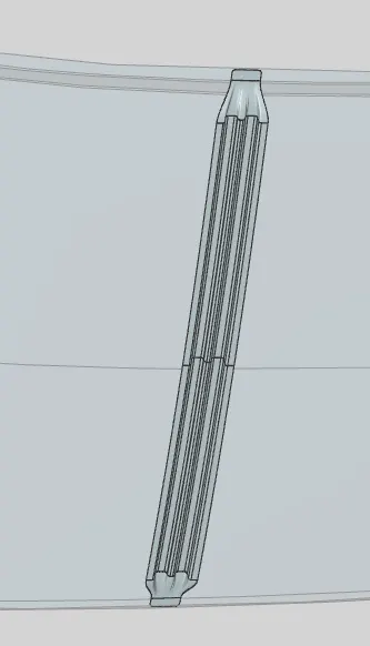
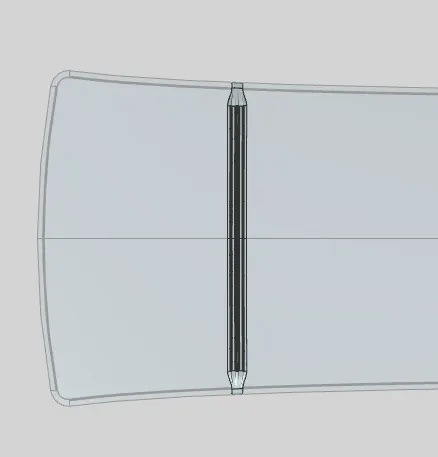
Bow Roof Rail 2
1) This Bow Roof Rail2 loactes between Centre Roof Rail and Rear Roof Rail
2) This is also Given Strenght for the Roof
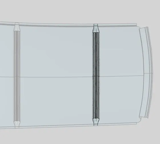
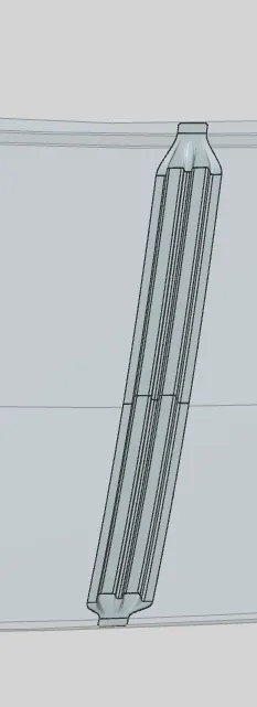
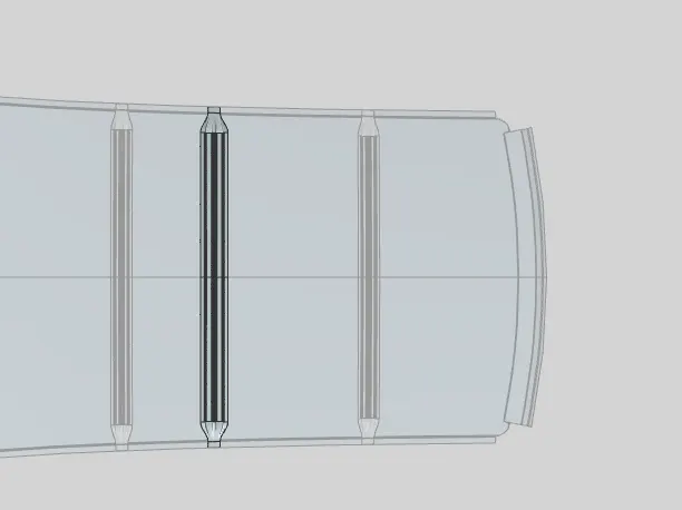
Center Roof RAil:
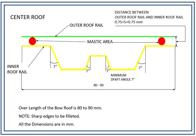
1) This Centre Roof Rail locates Around Center portion of Roof Outer
2) It is supports the Roof as well attching with B -Pillar
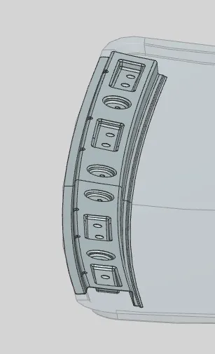
Rear Roof Rail:
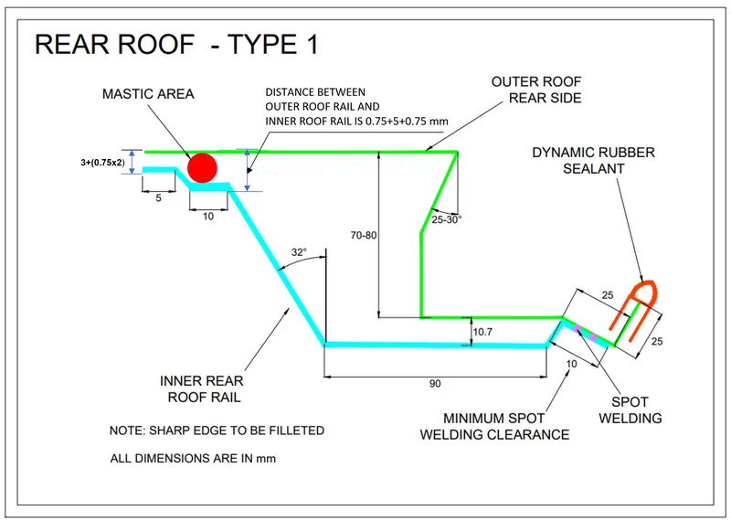
1) This Rear Roof Rail locates Rear end portion
2) It supports the Tailgate for vehicle
3) the Main criteria is Head room clearance for design
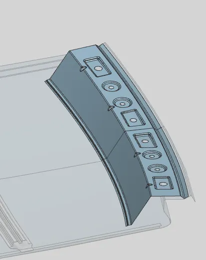
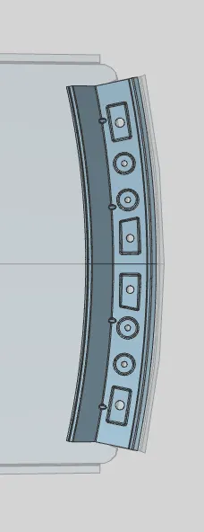
Main Criteria for Roof Design is
1) Heat Distortion
2) Snow Load Prediction
1) Heat Distortion:
HEAT DISTORTION CRITERA CALCULATION
Bow–roof prediction Formula
W = [1.73 x 10^(-3) x L] + [1.85 x 10^(-8) x (R^2)/t] + [ 1.10x10^(-3) x l] - 2.68
Judgement Condition : OK< 2.7> 3.1
Where
L = Roof Length in X-Direction[mm](Roof dimension in 0-Y)
R = Roof curvature
R = 2(Rx*Ry)/(Rx+Ry)
Rx = X curvature
Ry = Y curvature
t = Roof plate thickness [mm]
l = Bow Roof Span [mm]

2) Snow Load Prediction:
Snow load Prediction formula
Qr = [Iy x t2] / [α x s x [(Rx + Ry)/2]2 x 10-8]
Note: The Qr value given over here is correct. There was a typo error in the formula given in the video.
Where
α = My x Lx2 x 10-12 , My = Y(Ly-Y)
Judgement condition = Qr ≥ 3.1
250 ≤ s ≤ 380
t = Roof plate thickness [mm]
Ly = Distance between the front and rear roof Rails on the Vehicle along with 0Y[mm]
Length of Roof panel with the center point between Roof rail Front /Rear as the front and rear reference point.
Lx = Distance between the Left and Right end of the roof on the Roof BOW [mm]
Width of the roof panel exposed on the surface.
Y = Distance front Front Roof Rail to Roof BOW[mm]
s = Distance for which Roof BOW bears divided load [mm]
s = L1/2 + L2/2
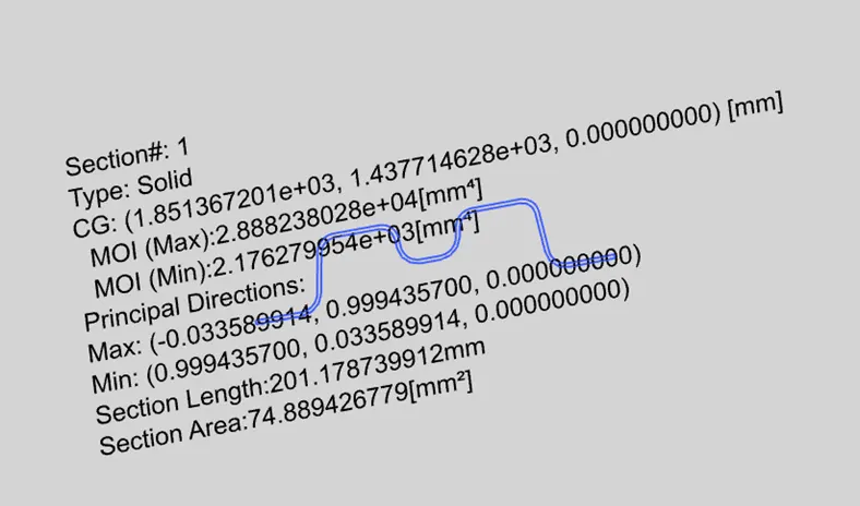
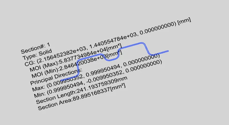
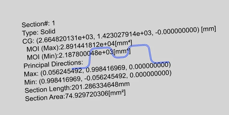
Iy = Geometrical moment of inertia of Roof BOW (Y cross-section )[mm4]
Rx = Lateral direction curvature radius of roof panel Y cross-section on Roof BOW [mm]
Roof panel curvature Radius of the Length Lx in Front view
Ry = Longitudinal Direction curvature radius of the Roof panel X cross-section on Roof BOW [mm]
Roof panel X curvature radius of length s in Side view

Section Inertia of Bow Roof Rail1
Section Inertia of Centre Roof Rail
Section Inertia of Bow Roof Rail2
Draft Analysis:
Roof Outer:

Front Roof Rail:
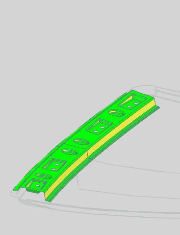
Bow Roof Rail 1:
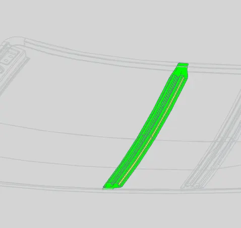
Centre Roof Rail;
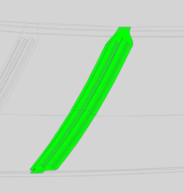
Bow Roof Rail 2
Rear roof Rail:
Assembling Process:
Mainly Spot welding and Mastics are used to attach the roof with sub elements and with Body
Spot Welding: Spot welding (also known as resistance spot welding) is a resistance welding process. This welding process is used primarily for welding two or more metal sheets together by applying pressure and heat from an electric current to the weld area.
Mastics attachments: The mastics are in Rubbery type of material which is in around 5-6 mm thickness and will support for fixing for two sheets where Welding is not possible.
CONCLUSION:
- The Roof and its reinforcements were designed successfully according to their master sections and criteria’s
- The Heat Distortion Criteria and Snow Load Criteria was fulfilled.
- The Draft analysis was also performed and the parts are found to be manufactural