Roof Design
- ROOF OUTER PANEL CREATION:
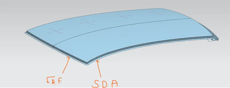
We make a smooth adges of all the sharp adges of the Input surface and created front roof flange according to the masster sectiom given. Now created a side ditch area as same as given in master section for the front roof flange and remove all the sharp corner by applynig blends operation according to the blend redius given in master section other wise applied minimum blend radius 3.75mm . Now for join the front roof flange and side ditch area with the help of THROUGH CURVE MESH (Command).
- DRAFT ANALYSIS:
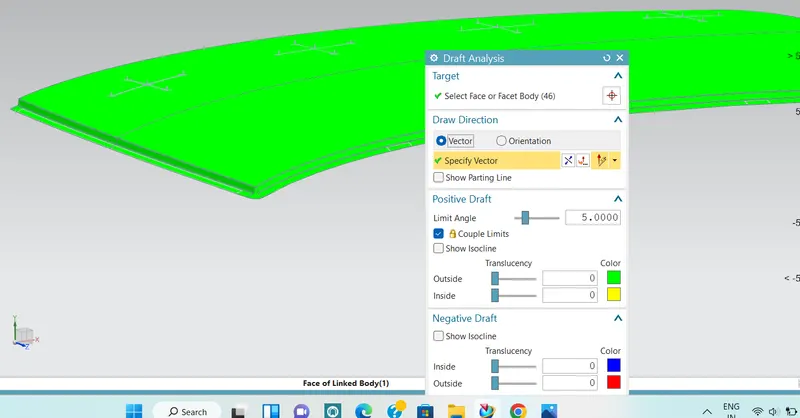
Now I have created the rear roof flange according to the master section given.
- FRONT ROOF RAIL CREATION:
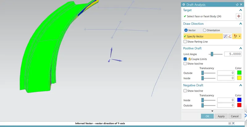
Now I have created the Front roof Rail according to the master section given.
Here i have provided the zero clearance in front side because there will be a spot weld in that area and in back side i have provided the clearance of 5mm for the mastic portion area.
now remove all the sharp corner by applynig blends operation according to the blend redius given in master section other wise applied minimum blend radius 3.75mm
- REAR ROOF RAIL CREATION:
Now I have created the REAR roof Rail according to the master section given.
- BOW ROOF RAIL1 CREATION
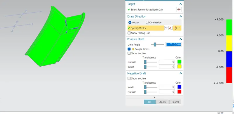
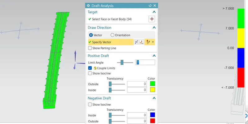
In bow roof rail 1 we offseted the input surface in downward direction to 6.5mm , 8mm and 2mm now trim it of and and create through curve to joint them after this, now remove all the sharp corner by applynig blends operation according to the blend redius given in master section other wise applied minimum blend radius 3.75mm.
It is necessary to kee the vertical surface angle greater than 7 degree
Now create a mastick area to and and offser the side ditch area to 1.5mm downward direction and trim this surface and use THROUGH CURVE MESH TO create new surface between them and then after SEW them make sure there must not be any small gaps between the surface, now mirror this surface to opposite of mid plane now thicken it.
- BOW ROOF RAIL 2 CREATION:
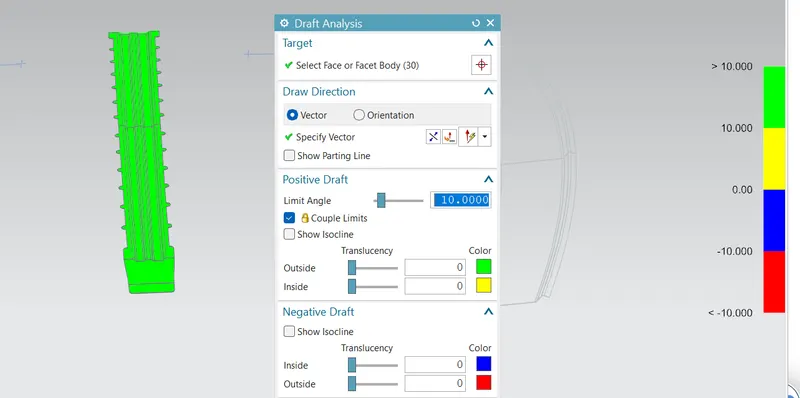
It has same design as bow roof rail 2 we offseted the input surface in downward direction to 6.5mm , 8mm and 2mm now trim it of and and create through curve to joint them after this, now remove all the sharp corner by applynig blends operation according to the blend redius given in master section other wise applied minimum blend radius 3.75mm.
It is necessary to kee the vertical surface angle greater than 7 degree
Now create a mastick area to and and offser the side ditch area to 1.5mm downward direction and trim this surface and use THROUGH CURVE MESH TO create new surface between them and then after SEW them make sure there must not be any small gaps between the surface, now mirror this surface to opposite of mid plane now thicken it.
- CENTRAL ROOF RAIL CREATION:
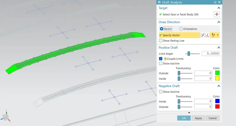
Here the widthe of the central roof rail is more than the bow roof rail 80- 90mm because it is at the midddile of the furface approximately.
we offseted the input surface in downward direction to 6.5mm , 8mm and 2mm now trim it of and and create through curve to joint them after this, now remove all the sharp corner by applynig blends operation according to the blend redius given in master section other wise applied minimum blend radius 3.75mm.
It is necessary to kee the vertical surface angle greater than 7 degree
Now create a mastick area to and and offser the side ditch area to 1.5mm downward direction and trim this surface and use THROUGH CURVE MESH TO create new surface between them and then after SEW them make sure there must not be any small gaps between the surface, now mirror this surface to opposite of mid plane now thicken it.
- BOW ROOF PREDICTION CALCULATION:
For this calculation we have to foolow the following procedure:
- Go to sketch and make a centre line in longitudinal direction
- Project the side most edges of the front roof rail and the bow roof rail
- Now create the points where our line gets intersect, here we will get two points from front roof rail and two points from the bow roof rail.
- Now finish the sketch.
- Now create the mid point between the front roof rail and bow roof rail.
- Create a middle point on the between the above point we got.
- Go to the same sketch and draw a vercticle line which is passing through this point we got above.
- Offset this line both side 100mm
- Offset the centre line downward 300 mm
- Offset this line both side 100 mm Create the points which is intersecting
- Here we willget a point like this
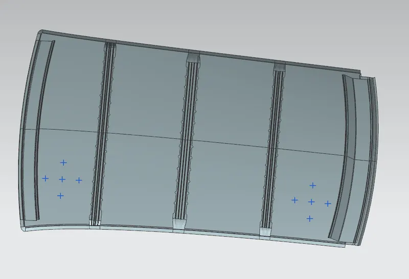
- Now project this ponts on the parts
- now create an arc between the points verticle and horizontal to get the value of Rx and Ry Respectively.
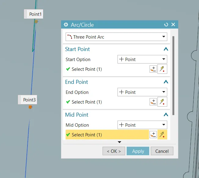
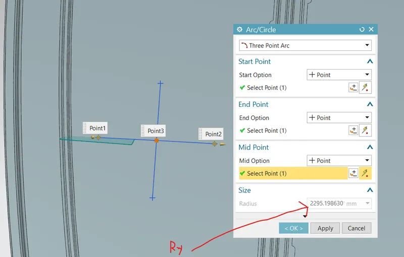
Following table Illustrate the Bow prediction Value:
| SR. no. | Rx | Ry | R | l | L | t | w |
| 1.FRR&BRR1 | 5737.78 | 2295.198 | 3278.819 | 347.329 | 2031.53 | 0.75 | 1.47 |
| 2.BRR1&CRR | 5049.96 | 5879.3 | 5433.16 | 440.6 | 2031.53 | 0.75 | 2.034 |
| 3CRR&BRR2 | 4049.135 | 10214.37 | 5799.33 | 453.63 | 2031.53 | 0.75 | 1.758 |
| 4. BRR2&RRR | 3262.46 | 14698.62 | 5339.73 | 400.23 | 2031.53 | 0.75 | 1.97 |
- SNOW LOAD PREDICTION:
For this calculation we have to foolow the following procedure:
- Create centre line and offet in both the direction 100mm
- Make a point on between the two bow roofs
- Crerate vericle lines passing through this mid point and offset it 100 mm both sides.
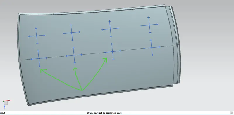
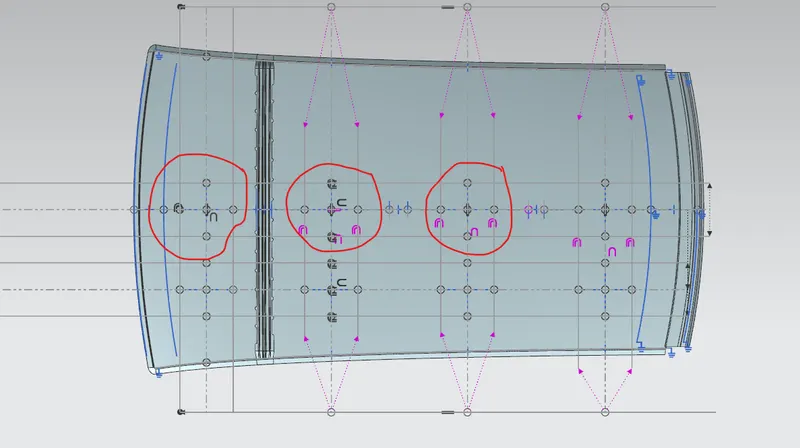
- now we get this point as shown in the below image
- and project it into the surface of the part
- and Draw a curve betweent the points to get the value of Rx and Ry
| SR. NO. | Iy | t | α | S | Rx | Ry | Qr. |
| 1FRR&BRR1 | 102.13 | 0.75 | 0.91 | 467.88 | 4697 | 23758.7 | 1.078 |
| 2BRR1&CRR | 142.1 | 0.75 | 1.2279 | 510.475 | 3754.83 | 5780.41 | 0.56 |
| 3CRR&BRR2 | 13.92 | 0.75 | 0.95 | 515 | 4239.87 | 10634.2 | 0.057 |