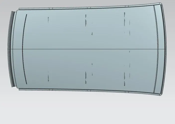
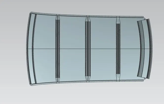
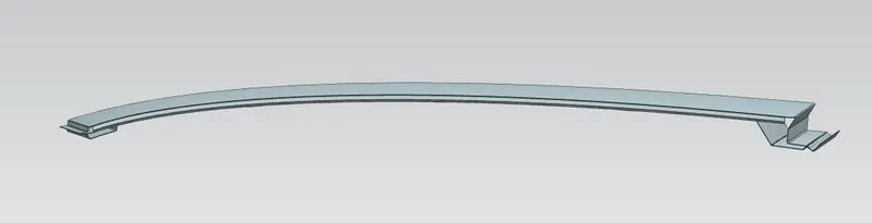
Roof Design
OBJECTIVE:- To design to roof of the car by using master section of front roof rail, centre roof rail, bow roof rail and rear roof rail and skin data.
Introduction- Roof is the top most part of automobile thats sits above passanger compartments which protects the pasanger from the wheather condition like sunlight, rain, wind and other external component. Also protect the pasanger from any injury when car roll over and crash during accident.
Component of roof-
- Front roof rail
- centre roof rail
- Rear roof rail
- Bow roof rail
Designing Consideration-
- Head roof clearance & visibility criteria- Minimum clearance between roof to head is 85mm
- Curvature study- curv surface improve the strength of roof compare to flate surface.
- Heat distortion and snow load criteria- Variation of temperature of atmosphere roof are expand and contract and load of snow so ability roof of car is sufficient strenght to beat this situation.
- Draft analysis- draft should be postive minimum 7 degree becouse if draft is negative stress concentration is more and punch die life is less.
Methodology- Design of roof in NX software by using skin data given by styling team and master section
- Ditch area of outer pannel- design using master section
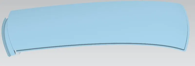
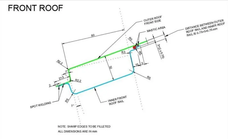
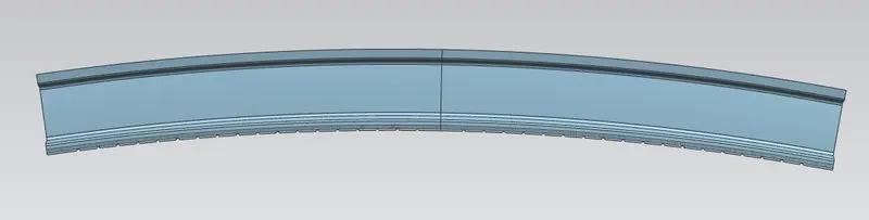
- Front roof rail- Front side of roof rail is join by spot welding and back side is join by mastics to improve the strenght of roof. master section & design are below
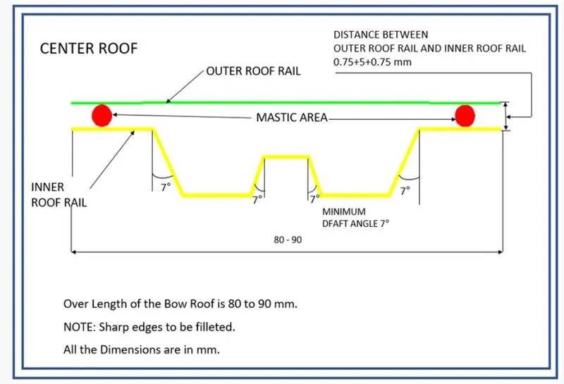
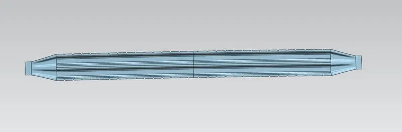
- Centre roof rail- The location of centre roof rail is to start flate suface area of outer pannel because flate region is beaker than curve region. It join by spot welding on ditch area and mastic by centre region. master section & design are below
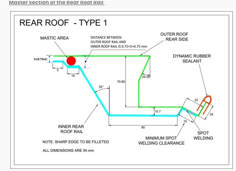
- Rear roof rail- It is located back side of outer pannel . It is join by spot welding and hing supported by back door. master section & design are below
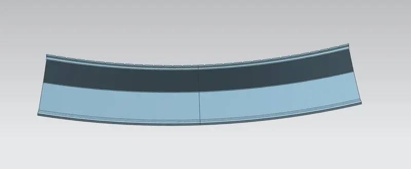
- bow roof rail 1 & 2- 1st bow roof location is between front roof rail and centre roof rail, 2nd Bow roof location is between centre roof rail and back roof rail. master section & design are below
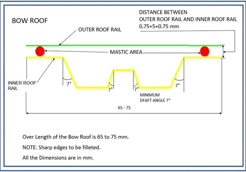
- The thickness of roof is 0.75 mm
- Minimum fillet radius is 3.75 mm
- Minimum draft angle should be 7 degree
Draft analysis-
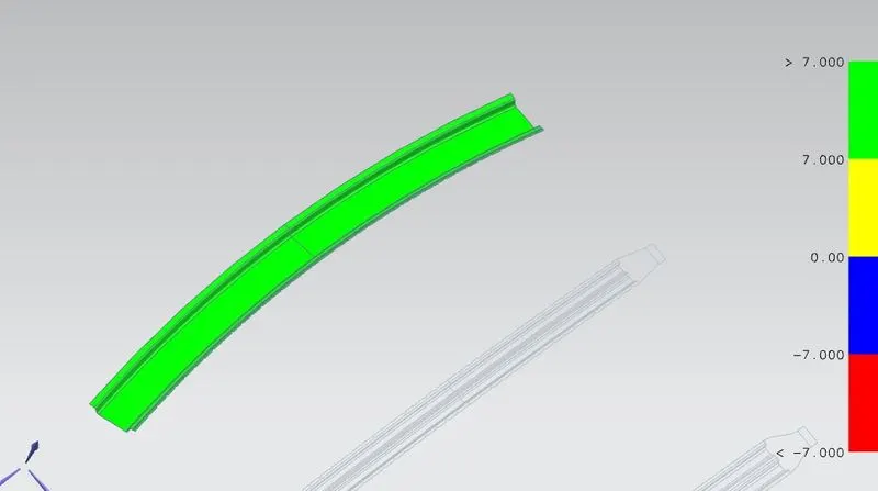
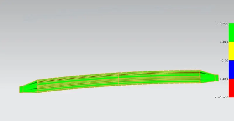
FRONT ROOF RAIL CENTRE ROOF RAIL
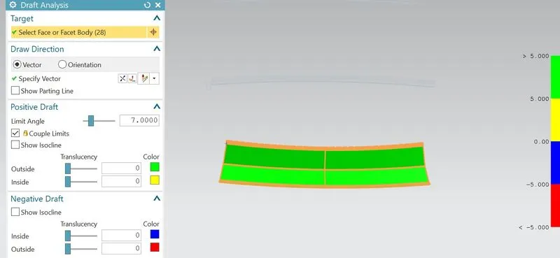
BACK ROOF RAIL
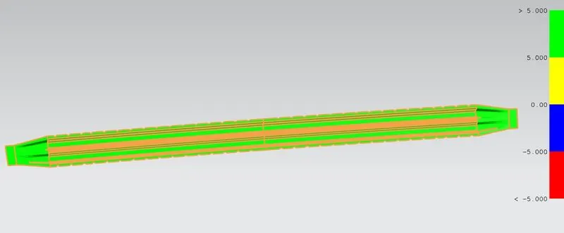
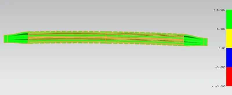
Bow roof 1st Bow roof 2nd
CALCULATIONS-
- HEAT DISTORTION ANALYSIS-
Bow–Roof Prediction Formula
W = [1.73 x 10^(-3) x L] + [1.85 x 10^(-8) x (R^2)/t] + [ 1.10x10^(-3) x l] - 2.68
Where,
L = Roof Length in X-Direction[mm](Roof dimension in 0-Y)
R = Roof curvature
R = 2(Rx*Ry)/(Rx+Ry)
Rx = X curvature
Ry = Y curvature
t = Roof plate thickness [mm]
l = Bow Roof Span [mm]
Judgment Condition
OK< 2.7
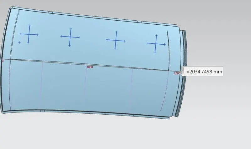 L = 2034.7498mm & t=0.75mm
- Case-l Front roof rail & bow roof 1st
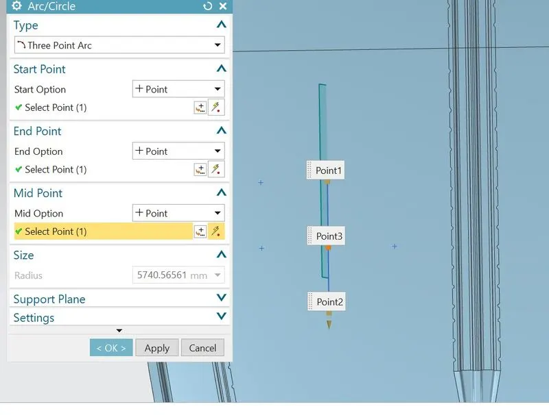
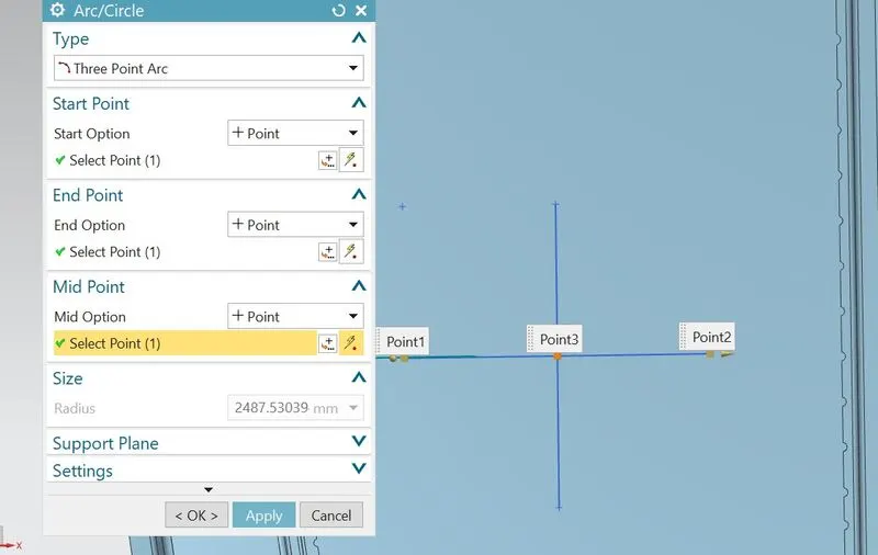
Rx=5740.5656mm , Ry=2487.53039mm
R=(2x5740.5656x2487.5303)/(5740.5656+2487.5303)
R=3470.9928mm
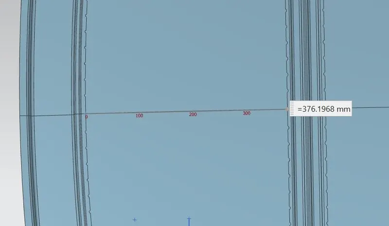
l=376.1968mm
W = [1.73 x 10^(-3) x 2034.7498] + [1.85 x 10^(-8) x (3470.9928^2)/0.75] + [ 1.10x10^(-3) x 376.1968] - 2.68
W = 3.52+0.297+0.413-2.68
W = 1.55
- Case-ll bow roof 1st & Centre roof rail
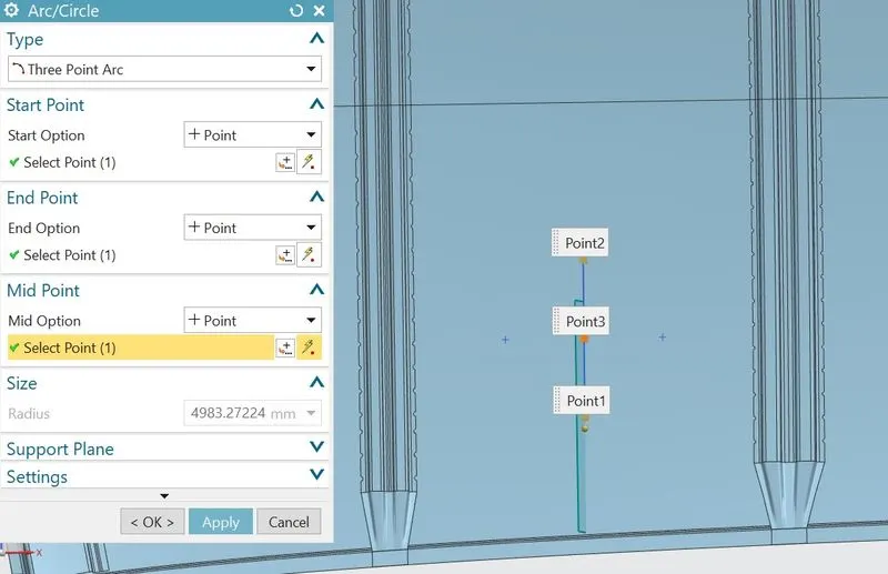
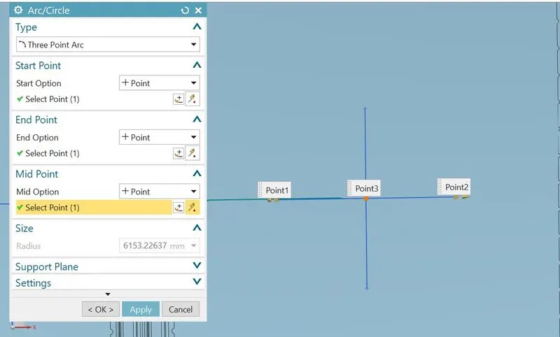
Rx=4983.27224mm , Ry=6153.22637mm
R=(2x4983.2722x6153.2263)/(4983.2722+6153.2263)
R=5506.7940mm
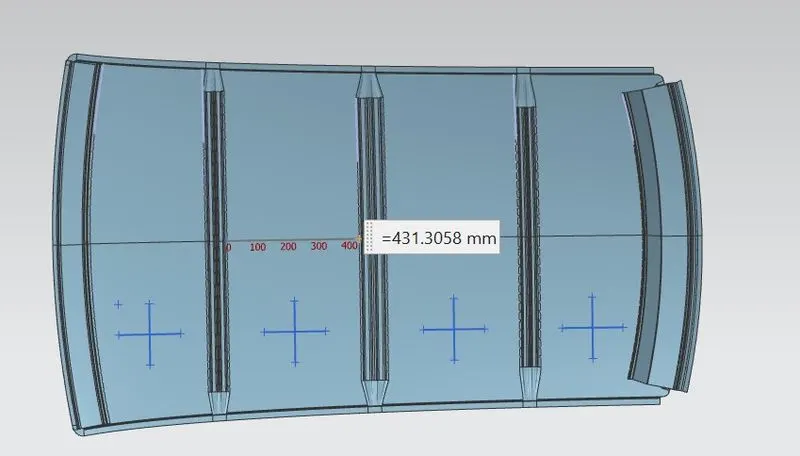 l=431.3058mm
W = [1.73 x 10^(-3) x 2034.7498] + [1.85 x 10^(-8) x (5506.7940^2)/0.75] + [ 1.10x10^(-3) x 431.3058] - 2.68
W = 3.52+0.748+0.474-2.68
W = 2.06
- Case-lll Centre roof rail & Bow roof 2nd
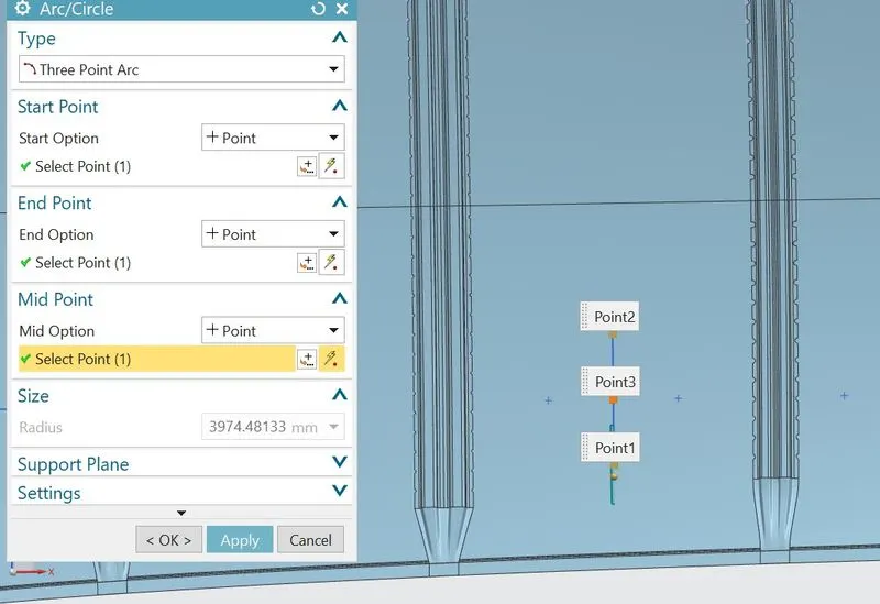
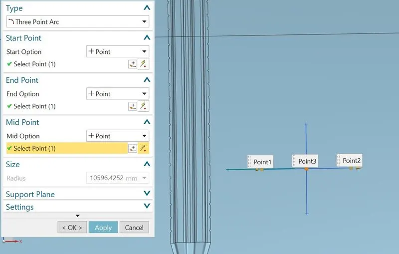
Rx=3974.48133mm , Ry=10596.4252mm
R=(2x3974.4813x10596.4252)/(3974.48133+10596.4252)
R=5780.7376mm
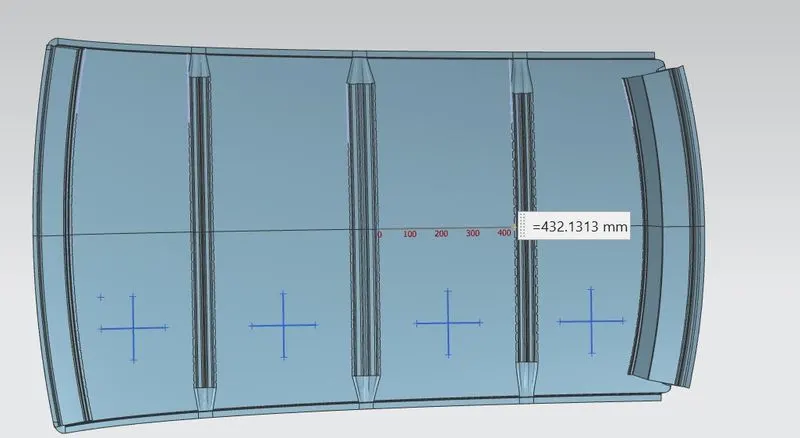 l=432.1313mm
W = [1.73 x 10^(-3) x 2034.7498] + [1.85 x 10^(-8) x (5780.7376^2)/0.75] + [ 1.10x10^(-3) x 432.1313] - 2.68
W = 3.52+0.824+0.475-2.68
W = 2.14
- Case-lV Bow roof 2nd & Back roof rail
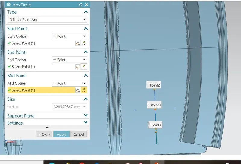
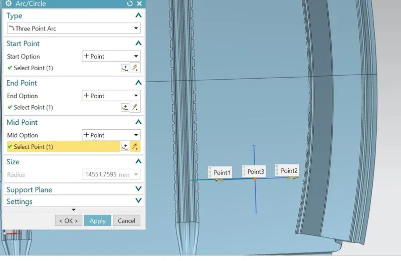
Rx=3285.72847mm , Ry=14551.7595mm
R=(2x3285.7284x14551.7595)/(3285.7284+14551.7595)
R=5360.9712mm
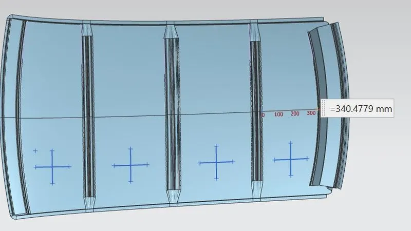 l=340.4779mm
W = [1.73 x 10^(-3) x 2034.7498] + [1.85 x 10^(-8) x (5360.9712^2)/0.75] + [ 1.10x10^(-3) x 340.4779] - 2.68
W = 3.52+0.709+0.374-2.68
W = 1.92
- SNOW LOAD ANALYSIS-
Snow Load Prediction Formula
Qr = [Iy x t2] / [α x s x [(Rx + Ry)/2]2 x 10-8]
Note: The Qr value given over here is correct. There was a typo error in the formula given in the video.
Where,
α = My x Lx2 x 10-12 , My = Y(Ly-Y)
t = Roof plate thickness [mm]
Ly = Distance between the front and rear roof Rails on the Vehicle along with 0Y[mm]
Length of Roof panel with the center point between Roof rail Front /Rear as the front and rear reference point.
Lx = Distance between the Left and Right end of the roof on the Roof BOW [mm]
The width of the roof panel is exposed on the surface.
Y = Distance front Front Roof Rail to Roof BOW[mm]
s = Distance for which Roof BOW bears divided load [mm]
s = L1/2 + L2/2
Iy = Geometrical moment of inertia of Roof BOW (Y cross-section )[mm4]
Rx = Lateral direction curvature radius of roof panel Y cross-section on Roof BOW [mm]
Roof panel curvature Radius of the Length Lx in Front view
Ry = Longitudinal Direction curvature radius of the Roof panel X cross-section on Roof BOW [mm]
Roof panel X curvature radius of length s in Side view
Judgment condition
Qr ≥ 3.1
250 ≤ s ≤ 380
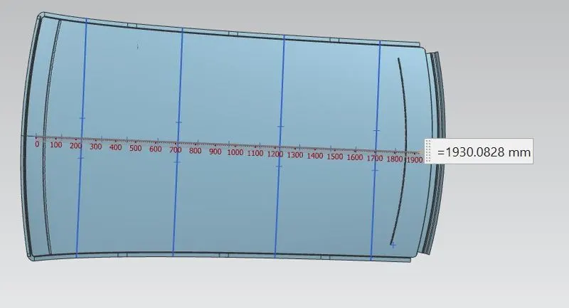 Ly = 1930.082 for all the cases
- CASE l Front roof rail & bow roof 1st
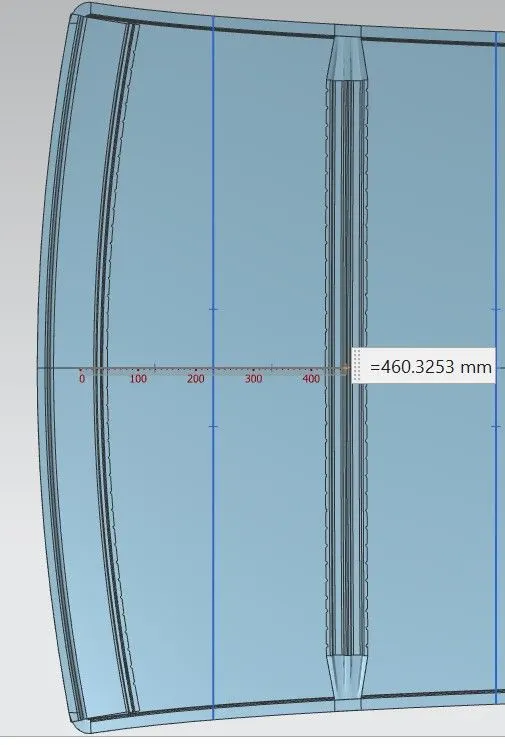
Y= 460.3253mm = L1 L2 = 511.82
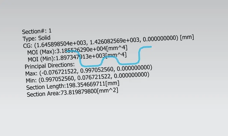
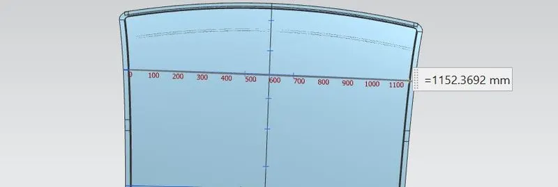
Iy = 1897.347 mm^4 Lx = 1152.36 mm
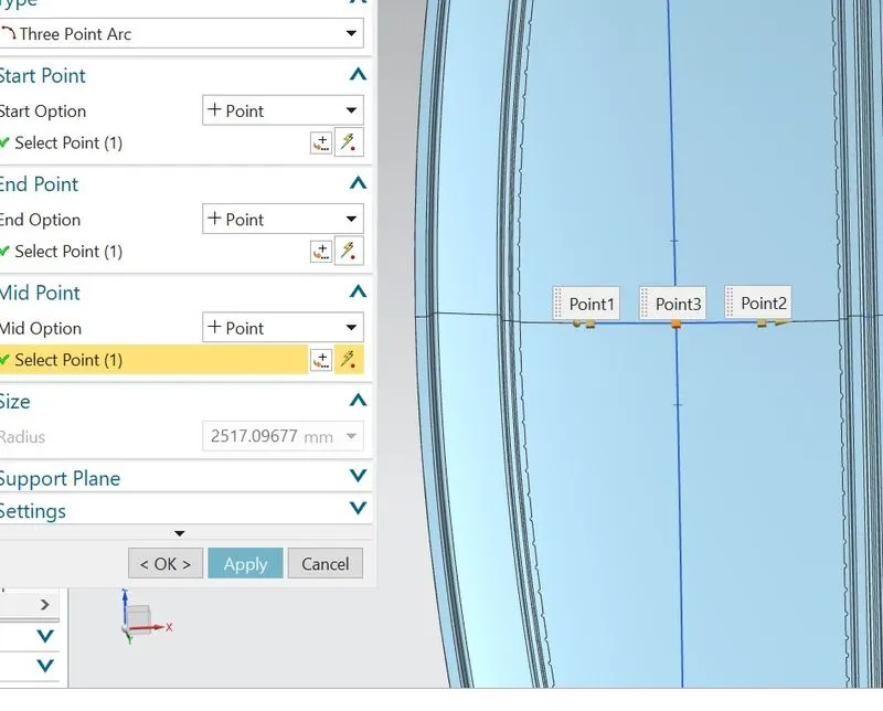
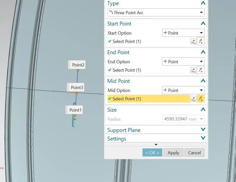
Ry = 2517.096mm Rx = 4590.33
My = Y(Ly-Y) = 460.3253(1930.082-460.3253) = 6,76,566.19 mm^2
α = 6,76,566.19 x 1152.362 x 10^(-12) = 0.8984
S = 460.325/2 + 511.82/2 = 486.0725
Qr = [1897.347 x 0.75^2] / [ 0.8984 x 486.0725 x [(4590.33+ 2517.09)/2]^2 x 10^-8] = 19.352
- CASE ll bow roof 1st & Centre roof rail
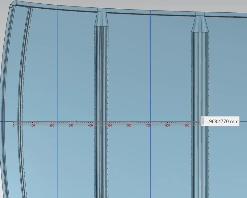
Y= 968.4770mm L2 = 512.22
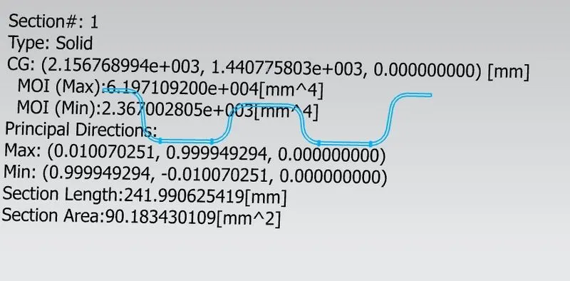
L1 = 511.82 mm Iy = 2367.00 mm^4
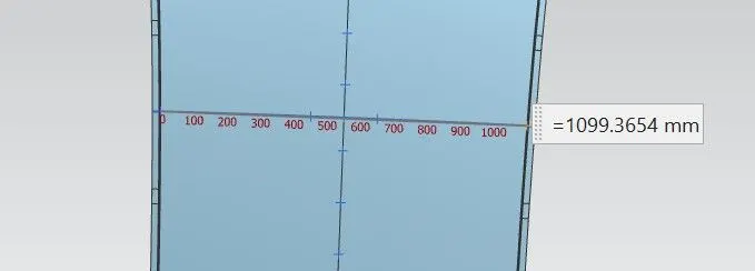
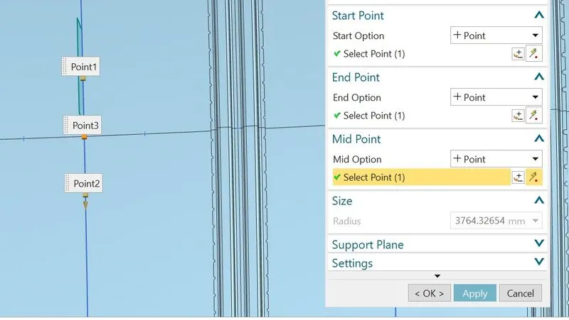
Lx = 1099.365 mm Rx = 3764.326 mm
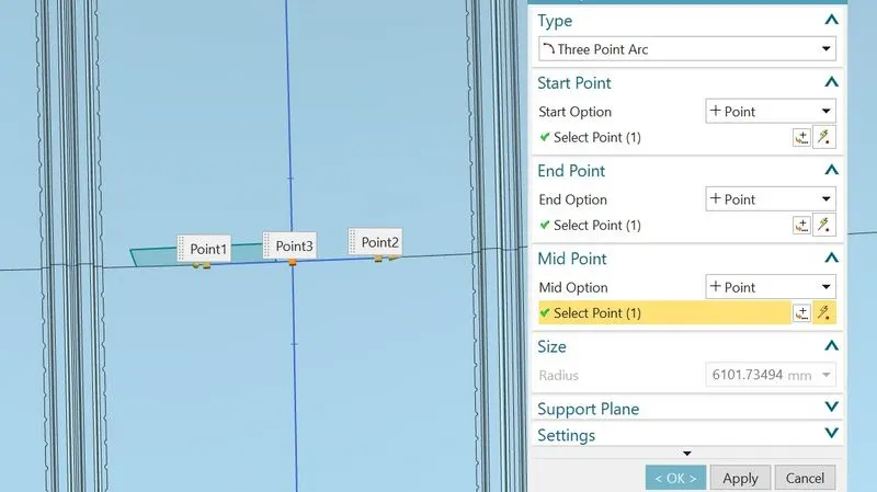 Ry = 6101.734 mm
My = Y(Ly-Y) = 968.4770(1930.082-968.4770) = 9,31,292.32 mm^2
α = 9,31,292.32 x 1099.362 x 10^(-12) = 1.125
S = 511.82/2 + 512.22/2 = 512.02
Qr = [2367.0028 x 0.75^2] / [ 1.125x 512.02 x [(3764.32+ 6101.73)/2]^2 x 10^-8] = 9.498
- CASE lll Centre roof rail & bow roof 2nd
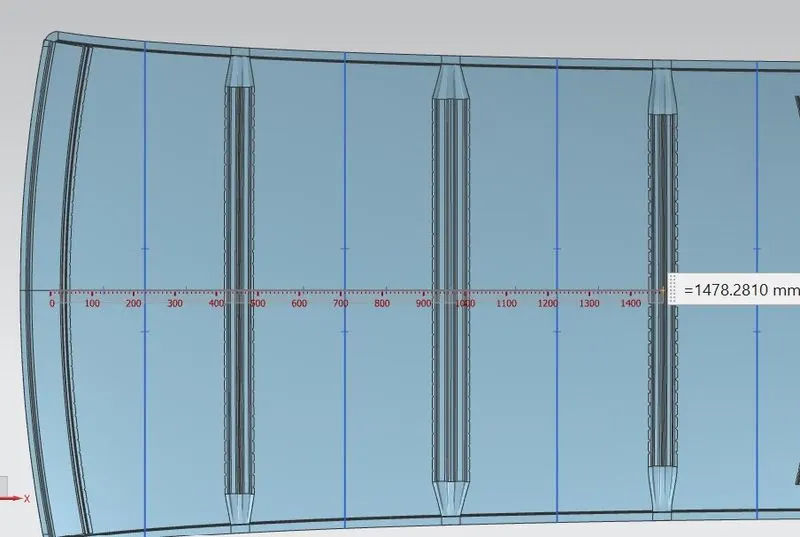
Y=1478.28mm L1 = 512.22
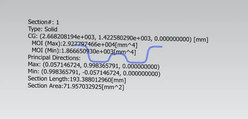
L2 = 465.107 mm Iy = 1866.65 mm^4
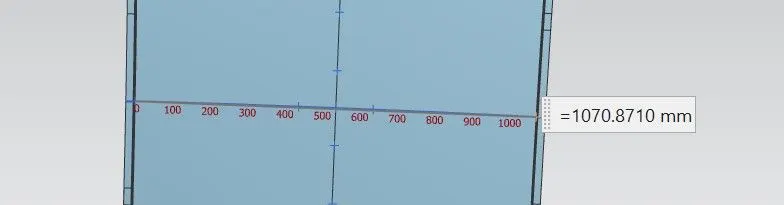
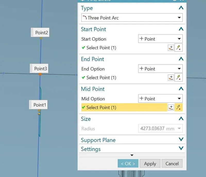
Lx = 1070.87 mm Rx = 4273.036 mm
 Ry = 11046.14 mm
My = Y(Ly-Y) = 1478.28(1930.082-1478.28) = 6,67,889.86056 mm^2
α = 6,67,889.86056 x 1070.872 x 10^(-12) = 0.765
S = 465.107/2 + 512.22/2 = 488.66
Qr = [1866.65 x 0.75^2] / [ 0.765 x 488.66 x [(4273.036 + 11046.14)/2]^2 x 10^-8] = 4.78
RESULT & OBSERVATION:-
Heat Distorsion Table
| SR. NO. | CASES | Rx | Ry | R | l | L | t | W | OK/NG |
| 01 | Front roof rail & bow roof 1st | 5740.5656 | 2487.53039 | 3470.9928 | 376.1968 | 2034.7498 | 0.75 | 1.55 | OK |
| 02 | Bow roof 1st & Centre roof rail | 4983.2722 | 6153.2263 | 5506.7940 | 431.3058 | 2034.7498 | 0.75 | 2.06 | OK |
| 03 | Centre roof rail & Bow roof 2nd | 3974.4813 | 10596.4252 | 5780.7376 | 432.1313 | 2034.7498 | 0.75 | 2.14 | OK |
| 04 | Bow roof 2nd & Back roof rail | 3285.7284 | 14551.7595 | 5360.9712 | 340.4779 | 2034.7498 | 0.75 | 1.92 | OK |
Snow load Table
| SR. NO. | CASES | Iy | a | Lx | Y | S | t | Rx | Ry | Qr | OK/NG |
| 01 | Front roof rail & bow roof 1st | 1897.347 | 0.8984 | 1152.36 | 460.3253 | 486.072 | 0.75 | 4590.33 | 2517.09 | 19.35 | OK |
| 02 | Bow roof 1st & Centre roof rail | 2367.00 | 1.125 | 1099.36 | 968.4770 | 512.02 | 0.75 | 3764.32 | 6101.734 | 9.49 | OK |
| 03 | Centre roof rail & Bow roof 2nd | 1866.65 | 0.765 | 1070.87 | 1478.28 | 488.66 | 0.75 | 4273.036 | 11046.14 | 4.78 | OK |
CONCUSION:- For given master section we have design ditch area of outer roof rail, front roof rail, centre roof rail, rear roof rail and 2 bow roof rail.
- The draft angle is postive and minimum 7 degree
- Heat distribution analysis, value of w for all case-l 1.55, case-ll 2.06, case-lll 2.14 and case-lV 1.92, which is less than 2.74 and satiesfied the condistion.
- Snow load analysis, value of Qr for all case-l 19.5, case-ll 9.49 and case-lll 4.78 which is gratter than 3.1 and satiesfied the condistion.
- The roof design sufficient strength and economical for given condition.