Roof Design
OBJECTIVE :
- The objective of this project is to design car roof with essential flanges and reinforcements like ditch area , front roof rail , bow roofs, central roof rail and rear roof rail for the the given styling surface
- Perform a curvature study on the roof and perform the calculations for the heat distortion and snow load criteria to determine whether the bow roofs are at the correct positions.
- Finding moment of inertia and section modulus for Bow roofs , central roof rail . front roof rail and rear roof rail .
- Perform the draft analysis for each reinforcements.
INTRODUCTION:
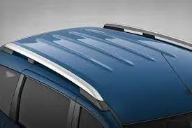
An automobile roof or car top is the portion of an automobile that sits above the passenger compartment, protecting the vehicle occupants from sun, wind, rain, and other external elements.
When it is seeing from outside of the car, it is just closing the top portion. But in design point of view, it is hard to create the design. Because of you have to create no of support rails for enough strength to withstand the load. Bow roofs are primarily fixed in flatter region to enhance strength.
Front roof and rear roof rails are fixed to the ditch area using spot weld operation. But front, rear bow roof and center roof rails are fixed to roof using mastic sealants. We don’t want so much gap between roof rails and bow roof area. So, we reducing the NVH issues.
DESIGN CONSIDERATION OF ROOF:
- Visibility criteria
- Head room clearance
- Bow roof position
- Heat distortion and Snow load criteria
- Draft analysis
ROOF CRUSH TEST:-
Roof crush test is the design given by the IIHS ( insurance institute of highway safety ) . After analyzing the many accidents IIHS has then fixed some regulations , that how to perform the crush test .
IIHS gives the rating based up on this test . For this they consider two points while giving the rating
- How fast the car can reforms to its original shape after the roll over and
- How deep is the protrusion after the roll over.
CURB WEIGHT MEASUREMENT:
Curb weight values used for calculating the SWR are based on IIHS measurements of a vehicle, not the manufacturer’s specified curb weight.
Vehicle curb weight is measured with full fluid levels using scales manufactured by Longacre Racing Products (Computer scales DX series 72634).
CALCULATING THE STRENGTH-TO-WEIGHT RATIO (SWR) RATING:
Force and displacement data are recorded for 5 seconds prior to each test, while the test system holds the loading platen at initial roof contact.
The data recorded from 1 to 4 seconds of this hold time are averaged for each channel to produce a measurement offset that is subtracted from the data recorded during the crushing of the roof.
After removing the offset for each channel, the force-displacement curve is plotted using the summed output from the five load cells and the average displacement from the four LVDTs. The maximum force prior to 127 mm of platen displacement is divided by the measured curb weight to obtain the SWR.
Both the force and curb weight are rounded to the nearest pound prior to performing the calculation, and the resulting SWR is rounded to the nearest one-hundredth of a unit.
Displacement is rounded to the nearest 0.1 mm. (The maximum displacement where the load can be used for the vehicle rating is 126.9 mm.) The vehicle’s rating is assigned based on the boundaries listed in.
HEAT DISTORTION STUDY ON THE ROOF :
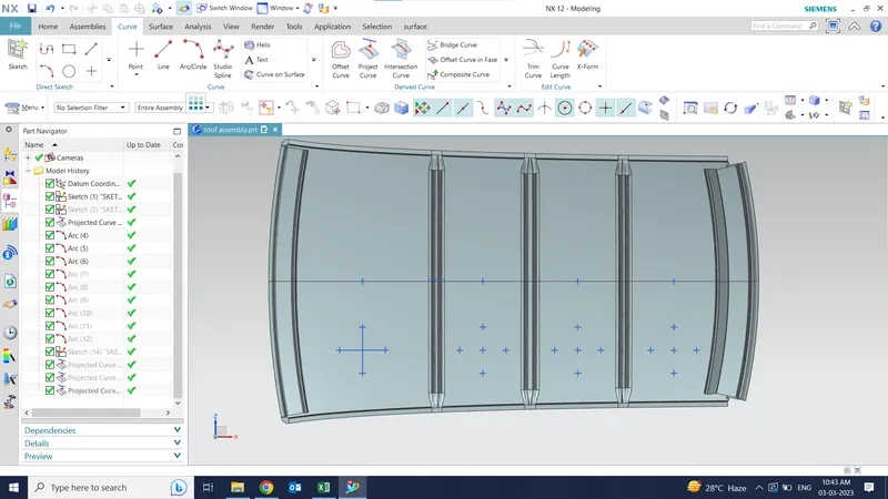
The heat distortion study plays a major role in sheet metal usage . heat distortion temperature is a temperature limit above which the material cannot be used for the structural applications . This study is used to predict the heat distortion temperature at where the material starts to soften when exposed to a fixed load at elevated temperature . In order to avoid bending or damages on the roof, based on the heat distortion temperature , this study will predict the bow roof position which helps to strengthen the roof .
Bow – roof prediction Formula
W = [1.73 x 10^(-3) x L] + [1.85 x 10^(-8) x (R^2)/t] + [ 1.10x10^(-3) x l] - 2.68
Where
L = Roof Length in X-Direction[mm](Roof dimension in 0-Y)
R = Roof curvature
R = 2(Rx*Ry)/(Rx+Ry)
Rx = X curvature
Ry = Y curvature
t = Roof plate thickness [mm]
l = Bow Roof Span [mm]
Judgement Condition : OK< 2.7> 3.1
| BOW ROOF CALCULATON | |||||||||
| W=[1.73 X 10^(-3) X L] /[1.85 X 10^(-8) X (R^2)/t] + [1.10 X 10^(-3)X I]-2.68] | |||||||||
| Length | Rx | Ry | R=2(Rx*Ry)/(Rx+Ry) | Thickness | I (Bow roof span) | W | |||
| FR TO BR-1 | 2032.426 | 5659.72 | 3220.325 | 4104.8 | 0.75 | 578.406 | 1.8 | ||
| BR-1 TO CR | 2032.426 | 4664.162 | 7446.384 | 5735.8 | 0.75 | 333.2215 | 2.01 | ||
| CR TO- BR-2 | 2032.426 | 3897.492 | 10987.9 | 5706.86 | 0.75 | 333.2215 | 1.8 | ||
| BR-2 TO RR | 2032.426 | 3274.444 | 14619.4 | 5350.4 | 0.75 | 364.699 | 1.9 | ||
APPLY THE VALUES IN THE FORMULA :
In order to find the heat distortion apply all the necessary values from the roof to the give formula
It can be concluded that all values of w<2.7 and also not w>3.1 so thus infers that current positioning of bow row are good in state as per design and found ok
Snow Load Prediction Formula
Qr = [Iy x t2] / [α x s x [(Rx + Ry)/2]2 x 10-8]
Note: The Qr value given over here is correct. There was a typo error in the formula given in the video.
Where,
α = My x Lx2 x 10-12 , My = Y(Ly-Y)
t = Roof plate thickness [mm]
Ly = Distance between the front and rear roof Rails on the Vehicle along with 0Y[mm]
Length of Roof panel with the center point between Roof rail Front /Rear as the front and rear reference point.
Lx = Distance between the Left and Right end of the roof on the Roof BOW [mm]
The width of the roof panel is exposed on the surface.
Y = Distance front Front Roof Rail to Roof BOW[mm]
s = Distance for which Roof BOW bears divided load [mm]
s = L1/2 + L2/2
Iy = Geometrical moment of inertia of Roof BOW (Y cross-section )[mm4]
Rx = Lateral direction curvature radius of roof panel Y cross-section on Roof BOW [mm]
Roof panel curvature Radius of the Length Lx in Front view
Ry = Longitudinal Direction curvature radius of the Roof panel X cross-section on Roof BOW [mm]
Roof panel X curvature radius of length s in Side view
Judgment condition
Qr ≥ 3.1
| SNOW ROOF CALCUATION | ||||||||||
| Qr = [Iy x t^2] / [α x s x [(Rx + Ry)/2]2 x 10^(-8)] | ||||||||||
|
|
||||||||||
| Iy | Thickness | α | S | Rx +Ry | Y | Lx | LY | Qr | ||
| Center of FR to BR-1 | 1.7989 X 10^(3) | 0.75 | 1.114 | 543.44 | 7391.079 | 678.755 | 1123.876 | 1979.099 | 21.75 | |
| center of BR-1 to CR | 1.842 X10^(3) | 0.75 | 1.124 | 408.137 | 5650.4 | 1083.793 | 1076.559 | 1979.099 | 12.58 | |
| center o f CR to BR-2 | 1.843 X 10^(3) | 0.75 | 0.084 | 456.102 | 7946.86 | 1488.965 | 1056.261 | 1979.099 | 7.86 | |
APPLY THE VALUES IN THE FORMULA :
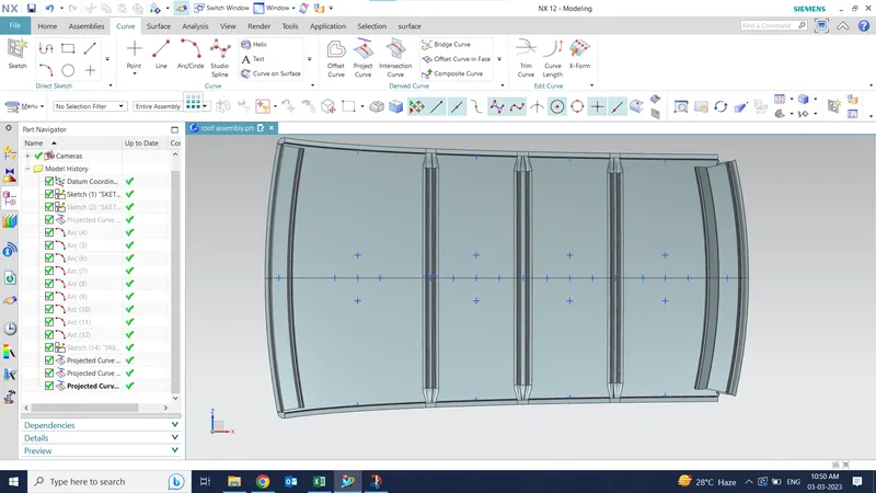
In order to find the snow load criteria apply all the necessary values from the roof to the give formulat is observed from the values that obtained values of QR > 3.1.
Section analysis:
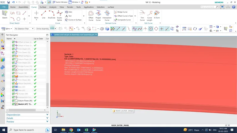
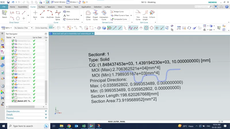
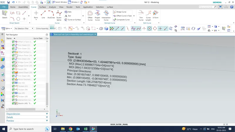
Section moment of inertia is used to predict the amount of deformation and deflection of a part. A higher moment of inertia is preferable as it reduces the amount of deflection for a given force. The thickness of the part and addition of flanges and embosses increase the section inertia of the part. Here the master sections of the roof and roof rails and their section analysis are given.
Center roof rail
Bow roof-1
Bow roof -2
DRAFT ANALYSIS :
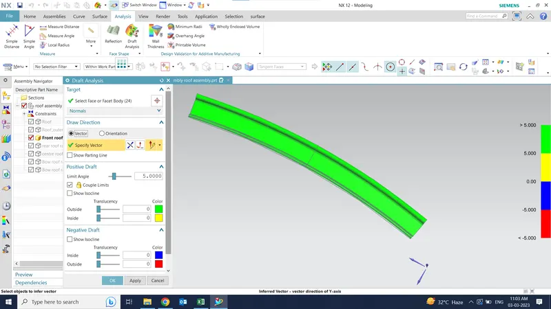
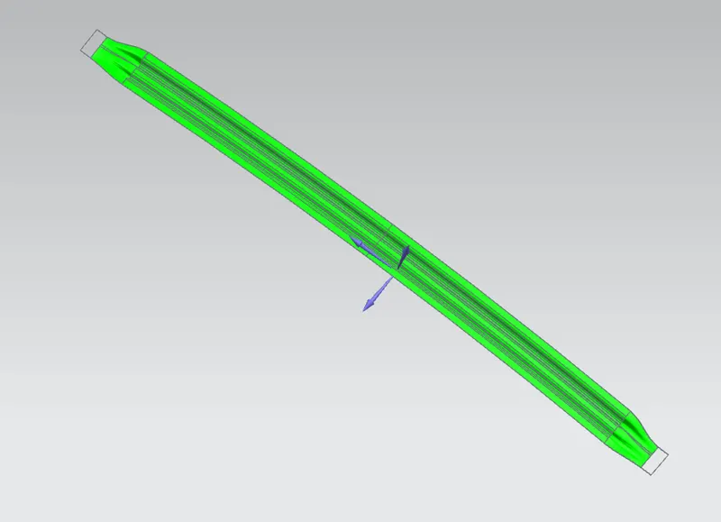
The Draft Analysis command enables you to detect if the part you drafted will be easily removed. This type of analysis is performed based on color ranges identifying zones on the analyzed element where the deviation from the draft direction at any point, corresponds to specified values.
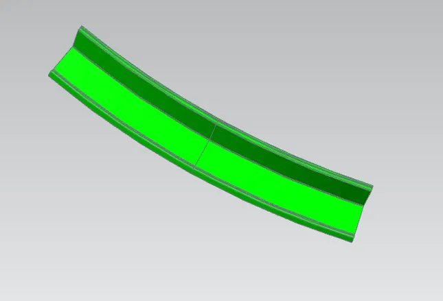
Minimum draft angle of 70 is considered for analysis . green colour infer on the parts that all face along the tooling direction has positive draft angle greater than 70 and passed in analysis
Draft analysis of front roof:-
Draft analysis of rear roof:-
Draft analysis of Bow roof -1
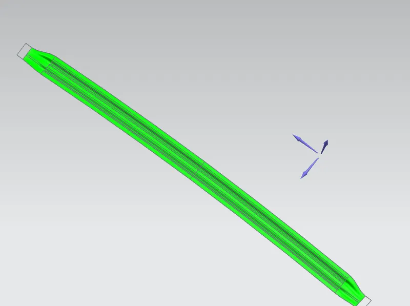
Draft analysis of center roof
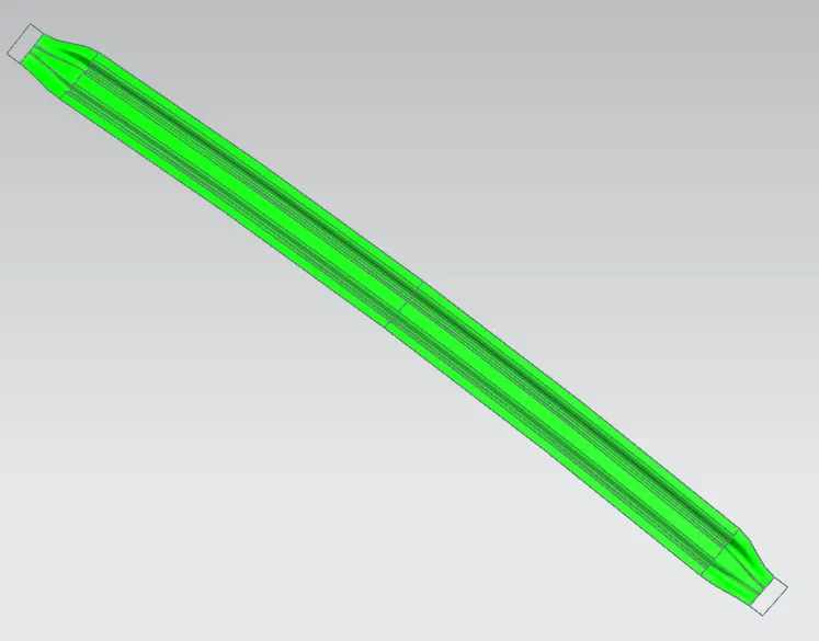
Draft analysis of bwo roof-2
CONCLUSION :
Hence the roof , front roof rail, bow roof rails , central roof rail and the rear roof rail is designed by following the master sections and the moment of inertia and draft analysis are carried out to check feasibility manufacturing