Roof Design
AIM: To a given roof styling, create essential flanges and reinforcements.
Objective:
To develop the essential flanges and reinfocements with appropriate dimensions and checking draft by using draft analysis. Calculating the Heat distortion, Snow load and section inertia on roof.
Software Used: NX CAD
Introduction:
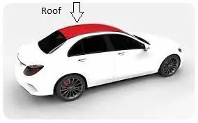
- An automobile roof is the portion of an automobile that sits above the passenger compartment, protecting the vehicle occupants from sun, wind, rain, and other external elements.
- Under the styling surface that is seen from the outside, there are many other structures under the roof that contribute to its strength and stability.
- The number of such reinforcement structures/supports differ with respect to the size of the vehicle. They are primarily installed on flatter areas of the roof to enhance strength.
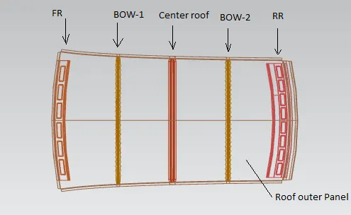
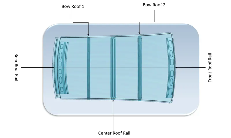
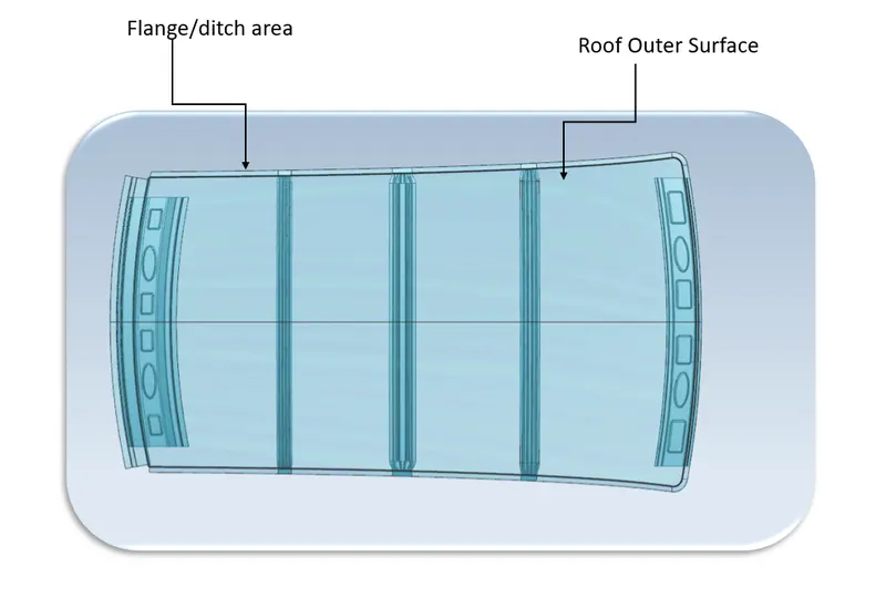
- These are the Front Roof Rail, Rear Roof Rail, Centre Roof Rail, and Bow Roof Design which are given Mastics and spot-welded to roof flanges & ditch areas and improve NVH value by increasing the strength of the roof using mastic sealants.
Design consideration of roof:
- Visibility Criteria
- Head clearance
- Curvature study
- Heat distortion and snow load criteria
- Draft analysis.
- Safety parameters
Design Of Roof Includes
- FRONT ROOF RAIL
- BOW ROOF 1
- CENTER ROOF RAIL
- BOW ROOF 2
Designing of the Parts of the Roof Assembly
Front Roof rail
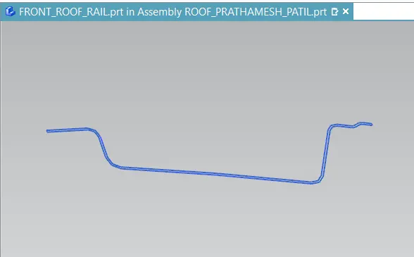
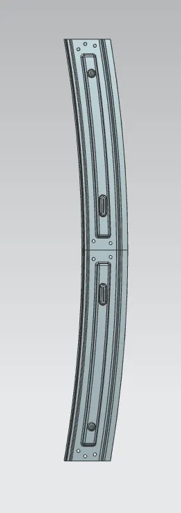
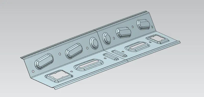
- Front roof rail is an additional part attached to the roof which gives the reinforcement and also having certain features in it which helps in attaching the bracket map lamp and the room lamp.
BOW ROOFS
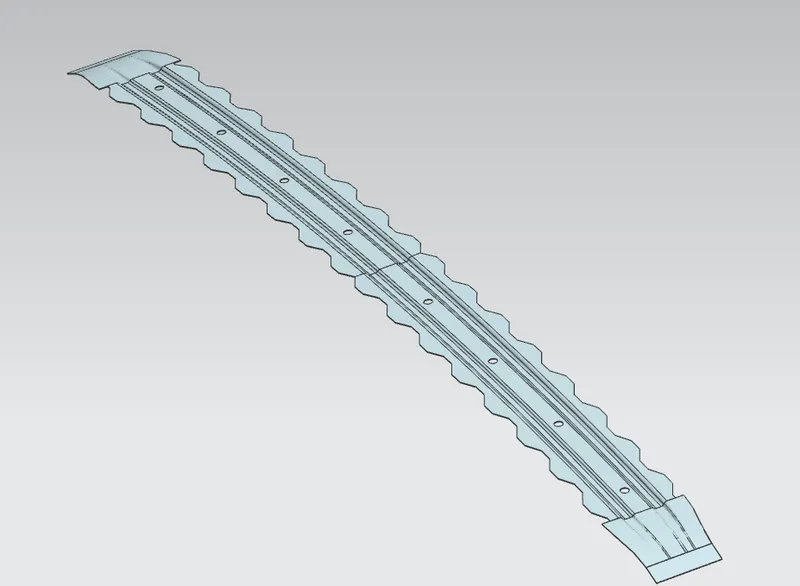
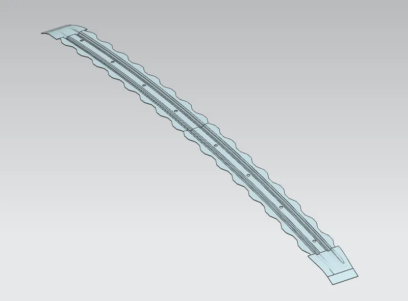
- Mastics are applied between roof and the roof rail and bow roof.When the mastic gooses out it joins the roof rail and bow roof with the Roof.
- As we have curvature in front and more flat in the back side of the roof,it is sufficient to have reinforcement in the center of the roof.
- If the roof was small with better curvature we need to use only one reinforcement (center) that wiil act as bow roof.
- No.of bow roof increases if the car size becomes longer and taller.If flat region increases bow roofs also increases.
Rear Roof Rail:
- It is the support which is joined to the back door and the body side outer and the inner panels.
- It is also usually made from body side outer scrap and therefore thickness of the rail is 0.75 mm. similar to the front roof design, we have to take into consideration the rear headroom clearance and the rear visibility criteria while designing the rear roof rail.
- Spot welds are applied at the backdoor end of the rail and the other end is joined with the roof using mastic sealants.
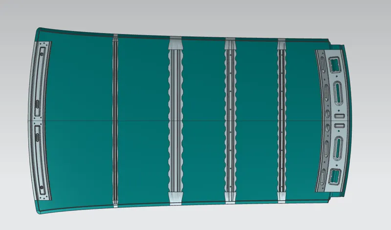
Assembled Images:
Front View
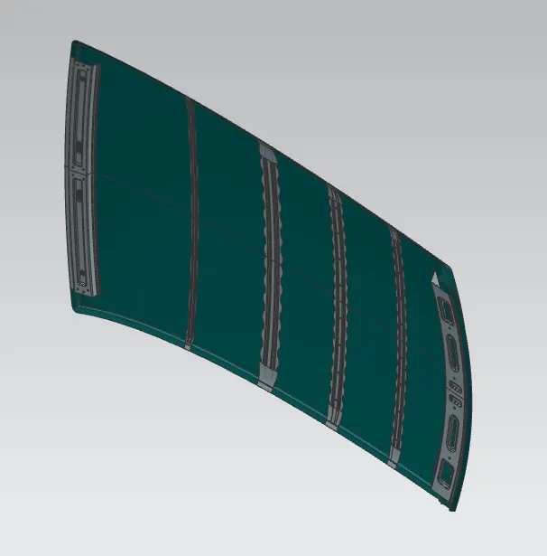
Isometric view:
Heat Distortion Calculations:
We have a data to calculate
W = [1.73 x 10^(-3) x L] + [1.85 x 10^(-8) x (R^2)/t] + [ 1.10x10^(-3) x l] - 2.68
Judgement Condition : OK< 2.7> 3.1
Where
L = Roof Length in X-Direction[mm](Roof dimension in 0-Y)
R = Roof curvature
R = 2(Rx*Ry)/(Rx+Ry)
Rx = X curvature
Ry = Y curvature
t = Roof plate thickness [mm]
l = Bow Roof Span [mm]
Here we have to find out the RX and Ry values. To find that
- Create a sketh on top roof and drawn a horizontal line at the centre.
- Then offset this line below 300mm and called it as -3Y line.
- From the _3Y line offset 100 mm above and below and convert all these line into refernece lines.
- Draw the verical lines at the middle of the each reinforcemnts and offset it to 100 mm both sides.
- Intersection point is created where the lines are met.
- Project these points to the outer roof panel.
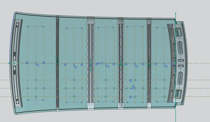
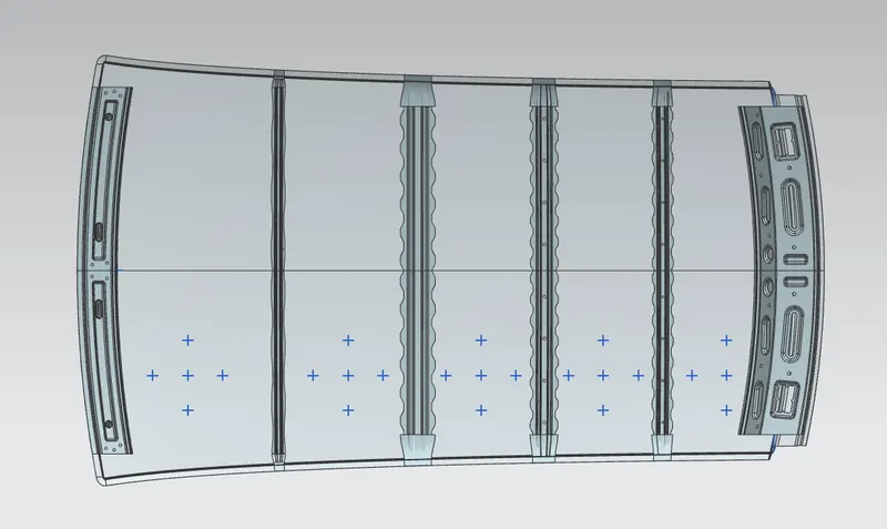
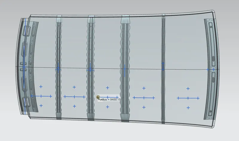
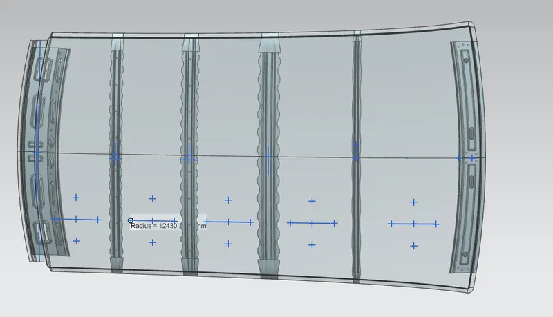
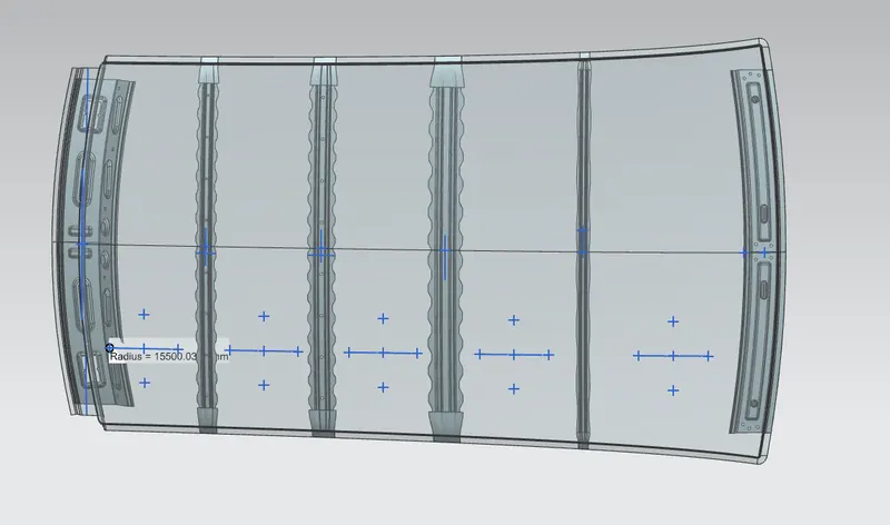
- Now draw the arc by connecting three points and measure the min radius value
RX value Images:
Front roof to Bow roof1 :
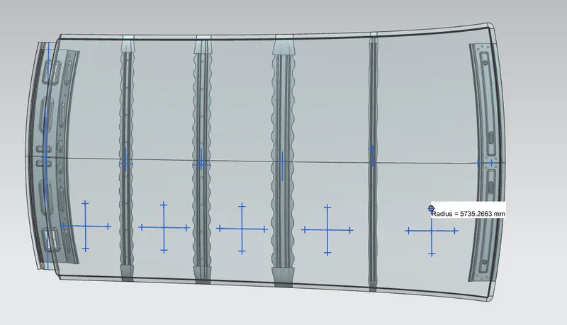
Bow roof 1 to Centre Reinorcement
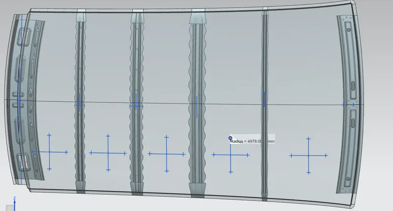
Centre Reinorcement to Bow roof 2
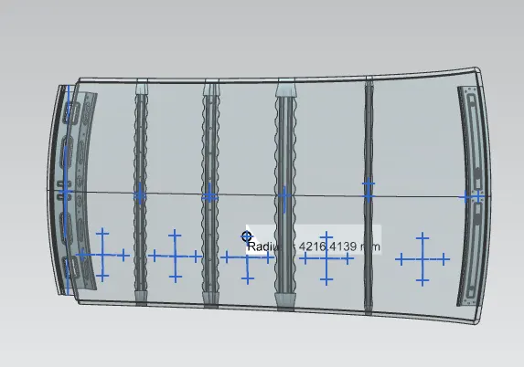
Bow roof 2 to Bow roof 3
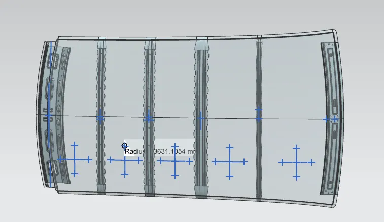
Bow roof 3 to Back roof Rail
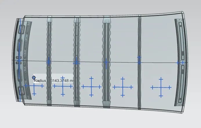
RY value images:
Front roof to Bow roof1 :
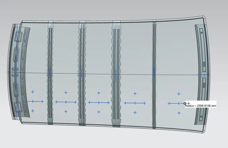
Bow roof 1 to Centre Reinorcement
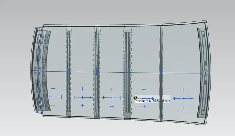
Centre Reinorcement to Bow roof 2
Bow roof 2 to Bow roof 3
Bow roof 3 to Back roof Rail
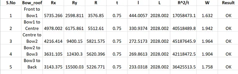
After doing the calculation, Here are the results.
Here
- 'l' value is from one reinforcement centre to other reinforcement centre value.
- 'L' value is total length from one end to another end.
According to the judgement criteria OK< 2.7> 3.1, All values are satisfied.
Snow Load Calculations:
We have a data to calculate
Qr = [Iy x t2] / [α x s x [(Rx + Ry)/2]2 x 10-8]
Note: The Qr value given over here is correct. There was a typo error in the formula given in the video.
Where
α = My x Lx2 x 10-12 , My = Y(Ly-Y)
Judgement condition = Qr ≥ 3.1
250 ≤ s ≤ 380
t = Roof plate thickness [mm]
Ly = Distance between the front and rear roof Rails on the Vehicle along with 0Y[mm]
Length of Roof panel with the center point between Roof rail Front /Rear as the front and rear reference point.
Lx = Distance between the Left and Right end of the roof on the Roof BOW [mm]
Width of the roof panel exposed on the surface.
Y = Distance front Front Roof Rail to Roof BOW[mm]
s = Distance for which Roof BOW bears divided load [mm]
s = L1/2 + L2/2
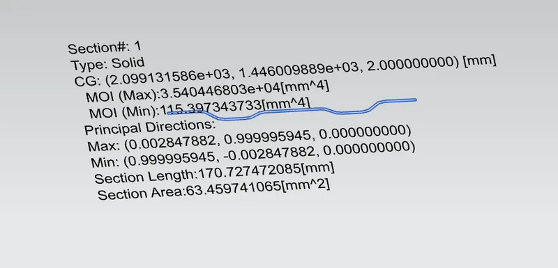
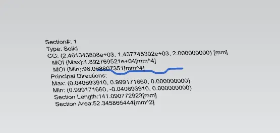
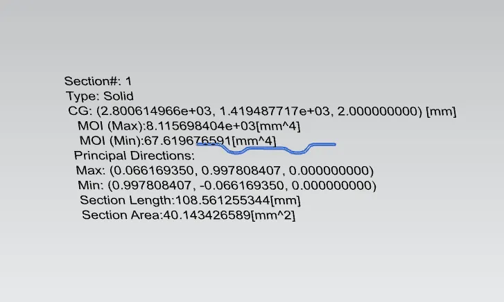
Iy = Geometrical moment of inertia of Roof BOW (Y cross-section )[mm4]
Rx = Lateral direction curvature radius of roof panel Y cross-section on Roof BOW [mm]
Roof panel curvature Radius of the Length Lx in Front view
Ry = Longitudinal Direction curvature radius of the Roof panel X cross-section on Roof BOW [mm]
Roof panel X curvature radius of length s in Side view
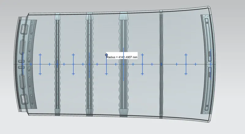
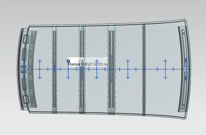
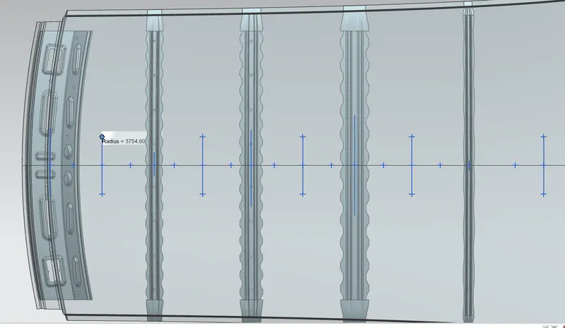
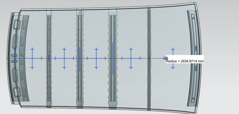
Here we have to find out the RX and Ry values. To find that
- Create a sketh on top roof and drawn a horizontal line at the centre.
- Offset this line to 100mm on both sides.Convert all these line into reference lines
- Draw the verical lines at the middle of the each reinforcemnts and offset it to 100 mm both sides.
- Intersection point is created where the lines are met.
- Project these points to the outer roof panel.
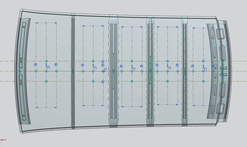
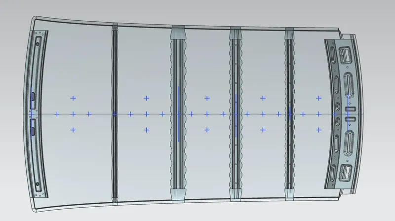
- Now draw the arc by connecting three points and measure the min radius value
RX value Images:
Front roof to Bow roof1 :
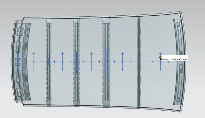
Bow roof 1 to Centre Reinorcement
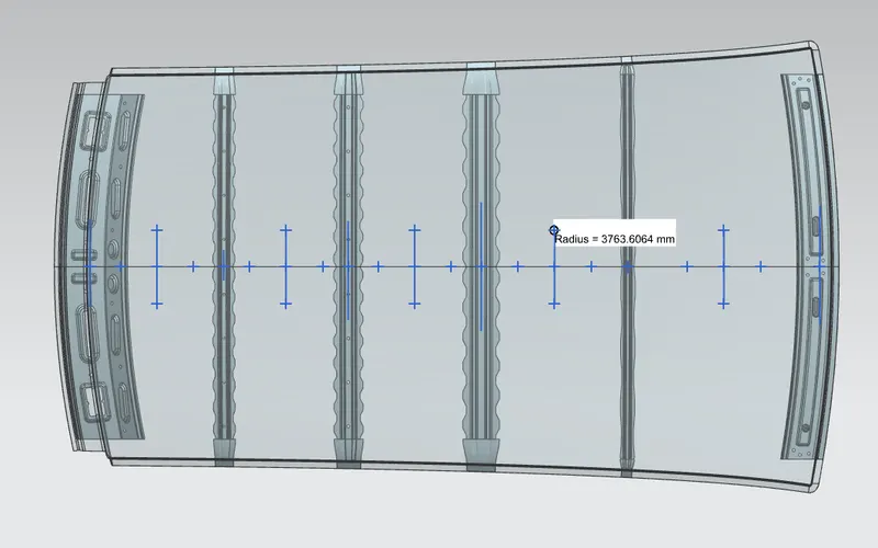
Centre Reinorcement to Bow roof 2
Bow roof 2 to Bow roof 3
Bow roof 3 to Back roof Rail
RY value Images
Front roof to Bow roof1 :
Bow roof 1 to Centre Reinorcement
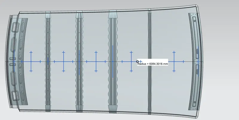
Centre Reinorcement to Bow roof 2

Bow roof 2 to Bow roof 3
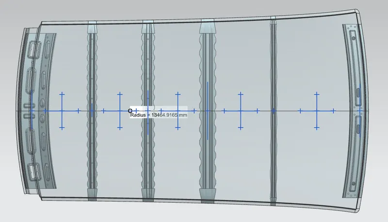
Bow roof 3 to Back roof Rail
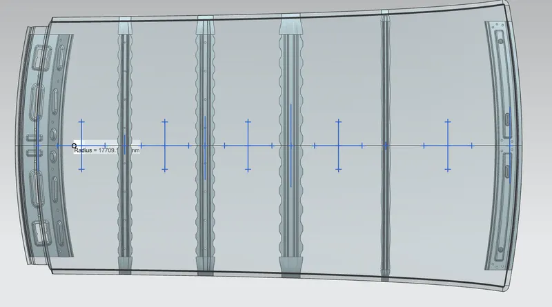
To find out the geometrical moment of Inertia , we created a intersection curve and used section inertia command.
Bow roof 1:
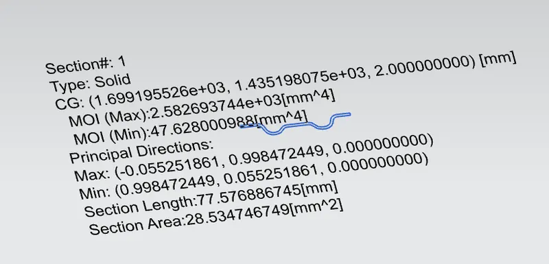
Centre Reinforcement:
Bow Roof 2:
Bow Roof 3:
After doing the calculation, Here are the results.
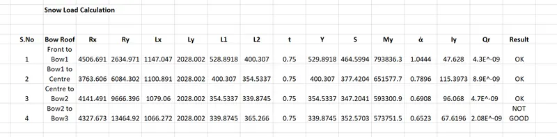
According to the judgement criteria Qr ≥ 3.1
Here one result of Qr is not fulfilling, this model will pass over to the styling team to change the curvature to improve the strength.
Draft Analysis:
Draft analysis was performed with 7 degrees value.
Front Roof Rail:
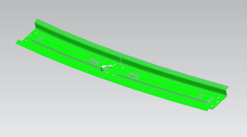
Bow roof 1:
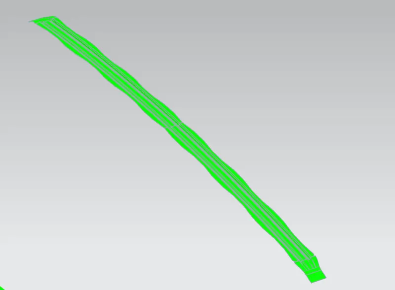
Centre Reinforcement:
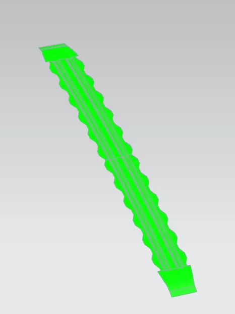
Bow Roof 2:
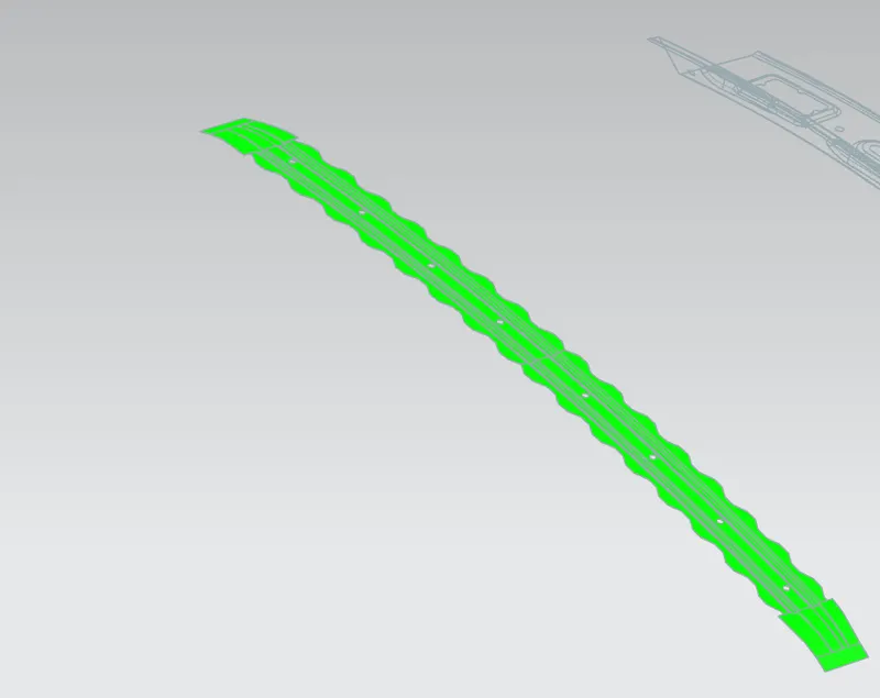
Bow Roof 3:
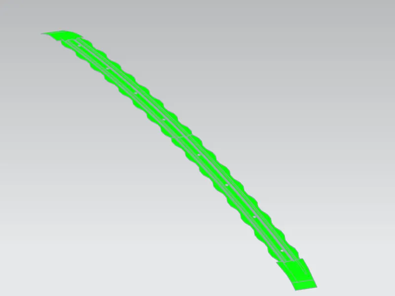
Back Roof Rail:
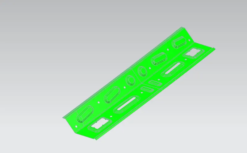
Outer Panel:
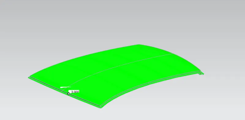
We have getting an issue in Outer Panel with negative draft analysis, So this part will be stamped with another tooling direction.
CONCLUSION :-
The roof has been successfully designed considering all the design Rules, Master sections, Manufacturing feasibility, Draft analysis, Heat distortion criteria, and snowload analysis.