Roof Design
OBJECTIVE :
- This study objective is to provide a car roof with the necessary flanges and reinforcements, such as the ditch region, front roof rail, bow roofs, centre roof rail, and rear roof rail for the stylistic surface that is provided.
- Determine whether the bow roofs are in the proper places by conducting a curvature analysis of the roof and making the necessary calculations for the heat distortion and snow load criteria.
- Calculating the section modulus and moment of inertia for Bow roofs with a central roof rail and both the front and back roof rails.
- Perform the draft analysis for each reinforcements
SOFTWARE USED: Siemens NX 12.0
- To design the Sheetmetal ROOF in NX by using some Solid/Surface features.
- NX Software is a flexible and powerful integrated solution that helps you deliver the products faster and efficiently.
- NX Cad software is widely used automotive, aerospace, thermal power station. Because of it is having modelling, drafting and manufacturing platform.
INTRODUCTION:
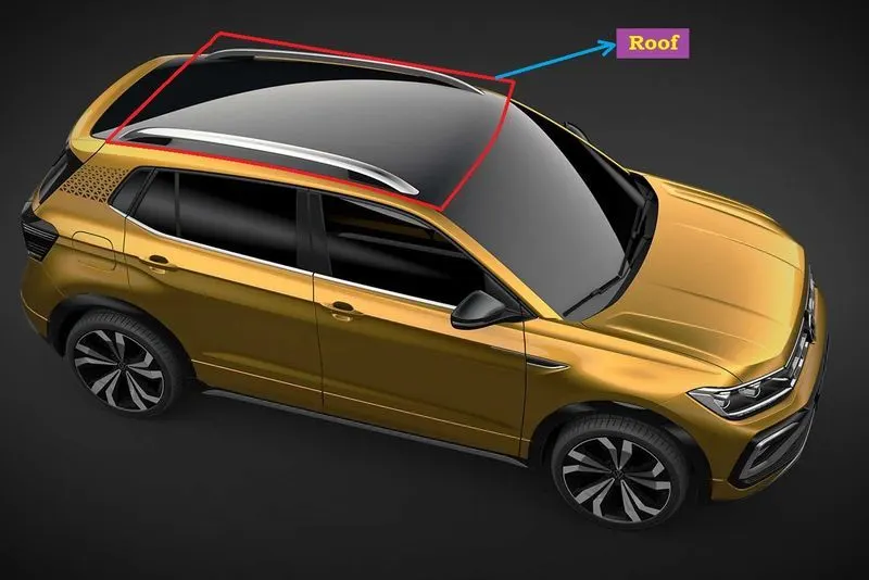
An automobile roof or car top is the portion of an automobile that sits above the passenger compartment, protecting the vehicle occupants from sun, wind, rain, and other external elements.
When it is seeing from outside of the car, it is just closing the top portion. But in design point of view, it is hard to create the design. Because of you have to create no of support rails for enough strength to withstand the load. Bow roofs are primarily fixed in flatter region to enhance strength.
Front roof and rear roof rails are fixed to the ditch area using spot weld operation. But front, rear bow roof and center roof rails are fixed to roof using mastic sealants. We don’t want so much gap between roof rails and bow roof area. So, we reducing the NVH issues.
Design Consideration of Roof:
- Visibility criteria
- Head room clearance
- Bow roof position
- Curvature study
- Heat distortion and Snow load criteria
- Draft analysis
Design Parameters:
The styling surface of a hardtop roof is given by the styling team to develop it. The car roof consists of outer panel and its reinforcements. Those reinforcements are as per below:
- Front Roof Rail
- Bow Roof
- Centre Roof and
- Rear Roof Rail
There are certain engineering standards to design the Automobile Roof. These standards are derived from trial and error method to reduce the Material wastage, production cost and to improve the safety over the years. These standards may vary region to region according to the conditions, usage, rules and regulations of that particular region. The common considerations for roof design are head room clearance, driving vision, heat distortion criteria and snow load criteria. The common standards for car roof design are the draft angle should be minimum of 7° and the blends should be minimum of 3+t (t-thickness of the sheet).
Master Section:
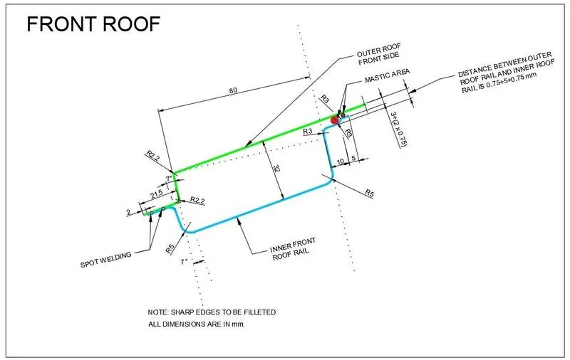
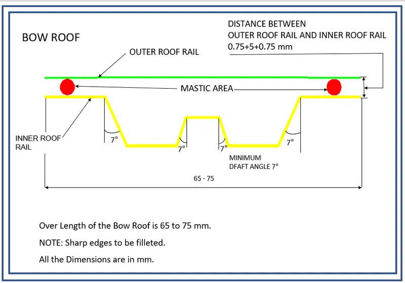
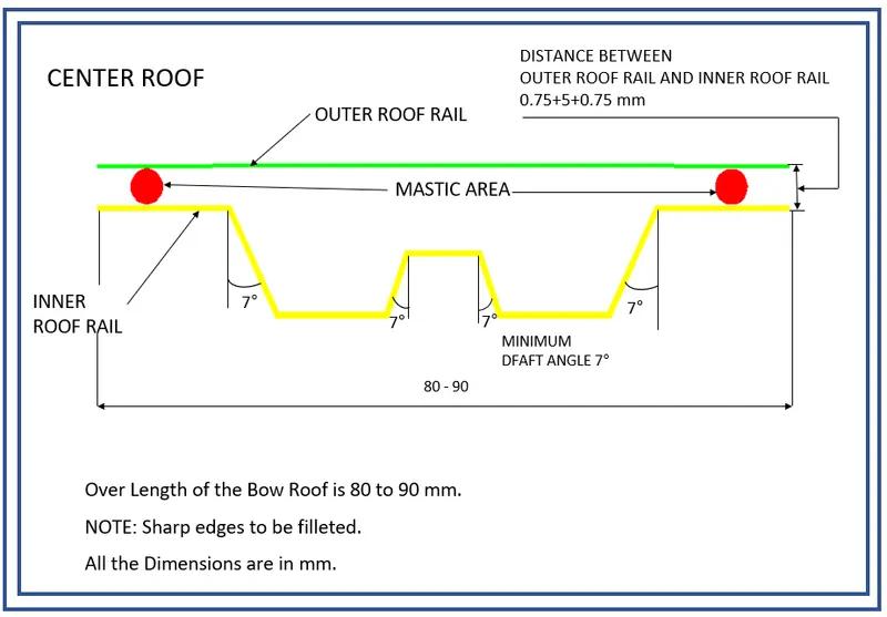
Master sections are the crosssection of 3D model. These master sections are widely used in OEMs and in automotive industries to convey the functional requirements of commodity to the design engineer. It gives the parameters like length, width, height, radius and clearance should be considered while designing the particular part or component.
1) Roof outer panel & front roof rail master section:
2) Bow roof master section:
3) Center roof master section:
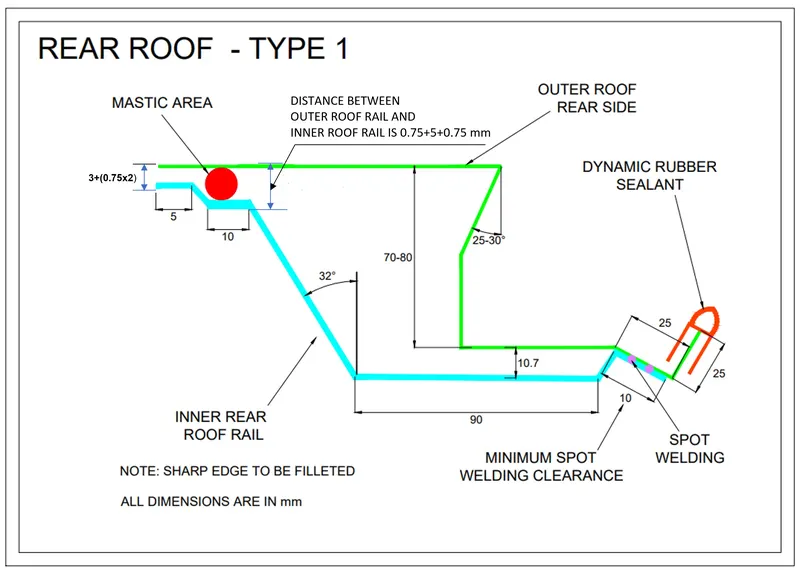
4) Rear roof rail master section:
Design procedure:
For designing this roof we first have to create the assembly file and adding the given styling surface first and by using this different roof rails is created as the separete part. The Roof rail which we must to create is as per below.
- Roof Outer Panel
- Front Roof Rail
- Bow Roof-1
- Center Roof Rail
- Bow Roof-2
- Rear Roof Rail
1) Roof Outer Panel :
The different views for the roof outer panel is given in below image.
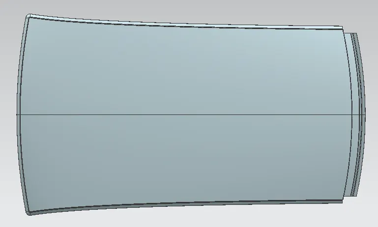
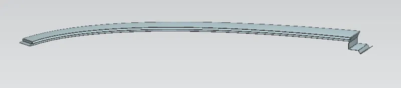
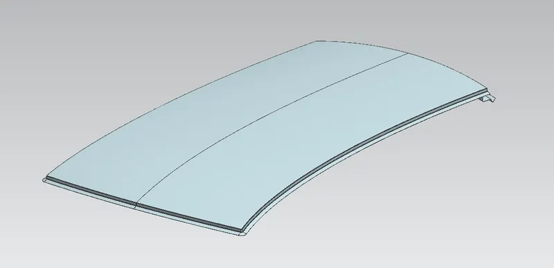
The roof outer panel is the aesthetic part of the roof and also it is the external part which covers the occupant or passenger compartment from the wind shield to the back door.
First of all Importing the The given styling surface and after that half of the portion of styling surface is extracted because the remaining one is the mirror of it. Now unntrimming this extracted surface to fill the gaps and holes and then trim it to remove the extra surface over boundries of styling surface.
Using law extension tool create the flanges as per the given master section from front roof rail as well as rear roof rail. After all flanges are done using edge blend tool the sharp edges is to be removed. Same as the ditch area is also created using the same law extension.
Also the sheet is extended to the Y axis and trimed with the xz plane so gap is removed and after that using mirror geomatery the whole surface is mirror and then using sew it is joined. Then the thickness of the 0.75mm is given to the surface by using the thicken command.
2) Front Roof Rail :
The different view for the Front roof rail is given as per the below image.
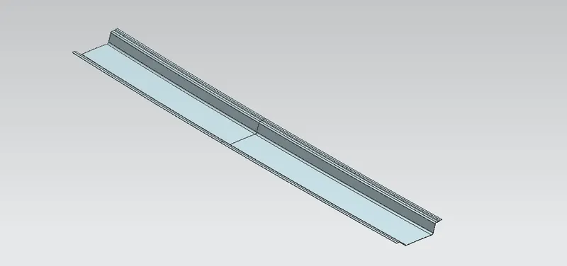
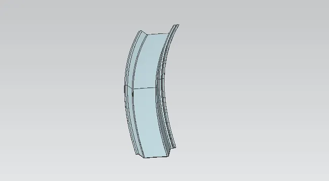
The reference surfaces for front roof are taken from the roof outer panel using the wave geometry linker command. By offsetting this surface as per the given master section we can create the reguired flanges. And by using law extension the verticle surface is created at the draft angle. by trim or corner we can remove the extra surface . after all surface is done as per master section using blend command the sharp edge is to be blended.
Using the sheet extend the whole surface is extended in the y direction and trim it using xz plane and then mirror whole surface and using sew the surface is to be join. After that using thiken command the whole surface is getting the thickness of 0.75mm. We can create the emboss in this surface by using emboss command.
3) Bow Roof - 1:
The different view for the Bow roof 1 is given as per the below image.
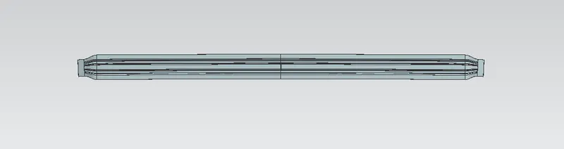
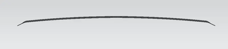
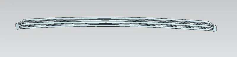
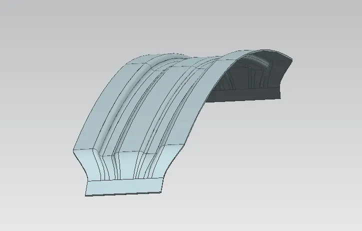
The reference surfaces for bow roof are taken from the roof outer panel using the wave geometry linker command. With help of these surfaces, the bow roof creation starts by offsetting it to the required dimensions according to bow roof master section. After the offsets, using the ‘offset curve in face’ command, required curve was offset to the required positions to remove the unwanted surfaces. and then mirror the whole surface and using the sew command it is joined together. And using thiken given the 0.75mm thickness.
4) Center Roof Rail :
The different view for the center roof rail is given as per the below image.
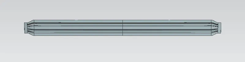
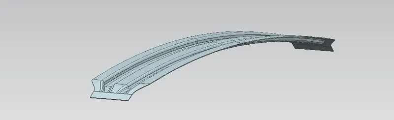
The reference surfaces for bow roof are taken from the roof outer panel using the wave geometry linker command. With help of these surfaces, the center roof creation starts by offsetting it to the required dimensions according to center roof master section. After the offsets, using the ‘offset curve in face’ command, required curve was offset to the required positions to remove the unwanted surfaces. and then mirror the whole surface and using the sew command it is joined together. And using thiken given the 0.75mm thickness.
5) Bow Roof - 2:
The different view for the Bow roof 2 is given as per the below image.
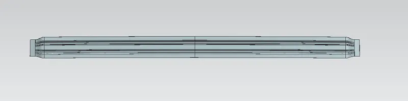
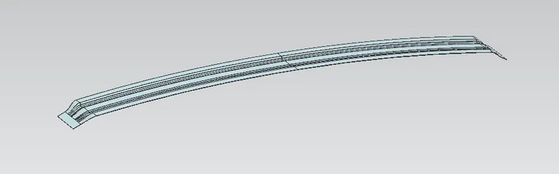
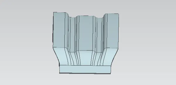
The reference surfaces for bow roof are taken from the roof outer panel using the wave geometry linker command. With help of these surfaces, the bow roof creation starts by offsetting it to the required dimensions according to bow roof master section. After the offsets, using the ‘offset curve in face’ command, required curve was offset to the required positions to remove the unwanted surfaces. and then mirror the whole surface and using the sew command it is joined together. And using thiken given the 0.75mm thickness.
6) Rear Roof Rail :
The different view for the Rear Roof Rail is given as per the below image.
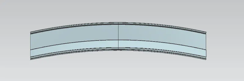
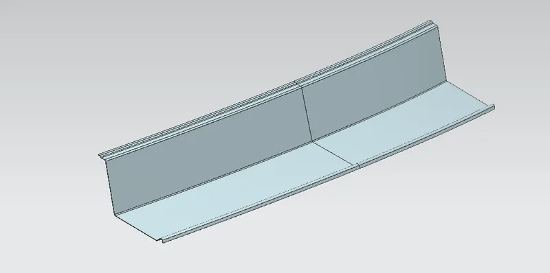
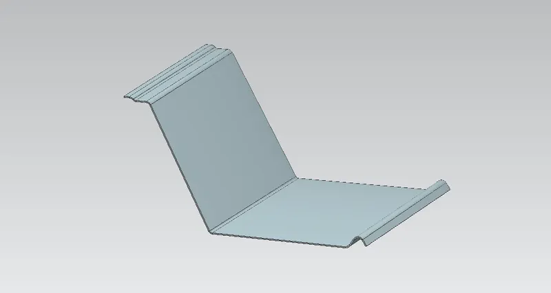
The reference surfaces for Rear roof are taken from the roof outer panel using the wave geometry linker command. With help of these surfaces, the rear roof creation starts by offsetting it to the required dimensions according to rear roof rail master section. After the offsets, using the ‘offset curve in face’ command, required curve was offset to the required positions to remove the unwanted surfaces. and then mirror the whole surface and using the sew command it is joined together. And using thiken given the 0.75mm thickness.
This roof rail joins with the back door and the roof. Inputs from the backdoor are taken into consideration for designing this roof rail. Here one end is joined using spot welding while the other end is joined using mastic sealants.
CURVATURE STUDY ON THE ROOF:
- Heat Distortion
- Snow Load
HEAT DISTORTION:
The heat distortion study the plays an important role in Sheetmetal application. Heat distortion is temperature limit above which material cannot be used for structural application. This study is useful to fin the where the material starts to soften when exposed to a fixed load at elevated temperature. In order to avoid the bending, damage to the roof based on the heat distortion temperature. This study will provide the which position of the bow roof give enough strengthen to roof.
Bow Roof Prediction Formula:
HEAT DISTORTION CRITERIA:
W = [1.73 x 10^(-3) x L] + [1.85 x 10^(-8) x (R^2)/2] + [1.10 x 10^(-3) x I]-2.68
Judgement Condition: OK<2.7>3.1
Where,
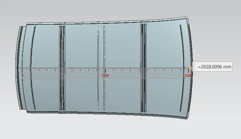
L= Roof Length in X- direction [mm](Roof Dimension in 0-Y)
R = Roof curvature
R = 2(RX*RY)/(RX+RY)
RX = X Curvature
RY = Y Curvature
t = Roof plate thickness [mm]
I = Bow roof span [mm]
Thickness for the Roof(t):
Roof Outer Panel, t= 0.75mm
Front Roof Rail, t = 0.75mm
Rear Roof Rail, t = 0.75mm
Bow Roof Rail Front, t = 0.75mm
Bow Roof Rail Rear, t = 0.75mm
Reinforcement roof rail, t = 0.75mm
ROOF LENGTH (L):
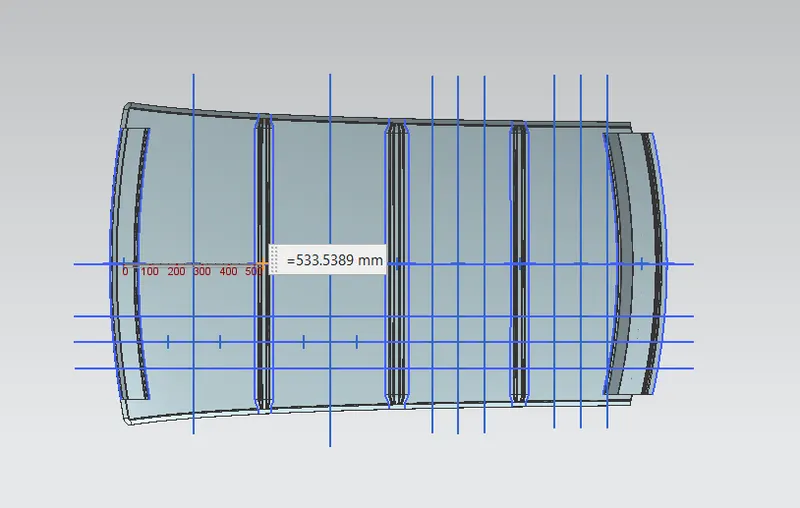
BOW ROOF SPAN (I):
Here we want to take the distance from front roof rail to bow roof front for finding the bow roof span(I), we want to measure another bow roof span also.,
RX & RY (X & Y Curvature):
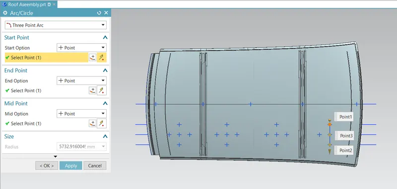
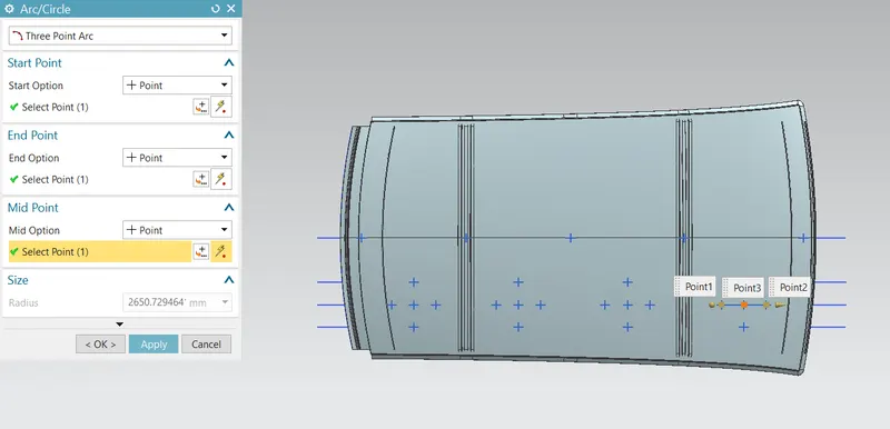
- From 0-Y axis, at -3Y about distance 300mm is drawn parallel on the perpendicular plane. After that 100mm lines are offset to either side of -3Y line. Now center lines are drawn between each adjacent roof rail edges respectively. Intersection points are marked on the sketch. Make all geometry lines are construction lines except points.
- Project the intersection points on sketch to the Roof surface.
- Join the intersection points in roof surface using the arc curve an measure the radius using the minimum radius comment.
RX Value:
RY Value:
FINAL RESULTS OF HEAT DISTORTION:
We have the necessary values for finding the heat distortion value(W):
W = [1.73 x 10^(-3) x L] + [1.85 x 10^(-8) x (R^2)/2] + [1.10 x 10^(-3) x I]-2.68
Apply the all the values,

From the above table we, conclude that all the values are of W< 2.7 and also W> 3.1. So, that all bow roofs areas are placed at the right place.
SNOW LOAD:
Snow load criteria study is used to check the durability of the roof to withstand the snow fall on the roof and reflex it is original shape without any permanent deformation after load being removed.
SNOW LOAD CRITERIA:
Qr = [IY x t2] / [α x s x [(RX + RY)/2]2 x 10-8]
Where,
α = My x LX2 x10-12, My = Y(Ly–Y)
Judgement condition = Qr > 3.1
250 < s < 380
t = Roof plate thickness[mm]
LY = Distance between the front and rear roof rails on the vehicle along with 0Y[MM],
Length of roof panel with the center point between roof rails front/ rear as the front and rear reference point.
LX= Distance between the left and right end of the roof on the roof bow[mm],
With of the roof panel exposed on the surface.
Y = Distance between Front roof rails to roof bow [mm],
s = Distance for which roof bow bears divided load [mm],
s = L1/2 + L2/2
Iy = Geometrical moment of inertia of roof bow (Y cross – section) [mm4],
RX = Lateral direction curvature radius of roof panel Y cross section on roof bow [mm4],
Roof panel curvature radius of the length LX in front view.
RY = Longitudinal direction curvature radius of the roof panel X cross section on roof bow[mm4],
Roof panel X curvature radius of length s in side view.
RX & RY (X & Y Curvature):
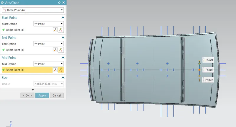
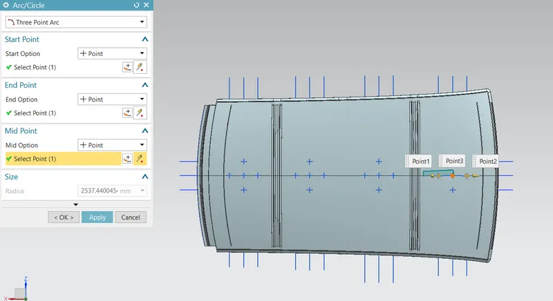
- At 0-Y axis on perpendicular plane to roof. Draw 100mm lines offset to either side of the of 0Y axis line. Now center lines are drawn between each adjacent roof rail respective. Intersection points are marked on the sketch. Make all the geometry in construction lines except points.
- Project the intersection points in the sketch are projected to roof surface.
- Join the project points using arc curve and measure the radius value using minimum radius comment.
RX Value:
RY Value:
LY Value:
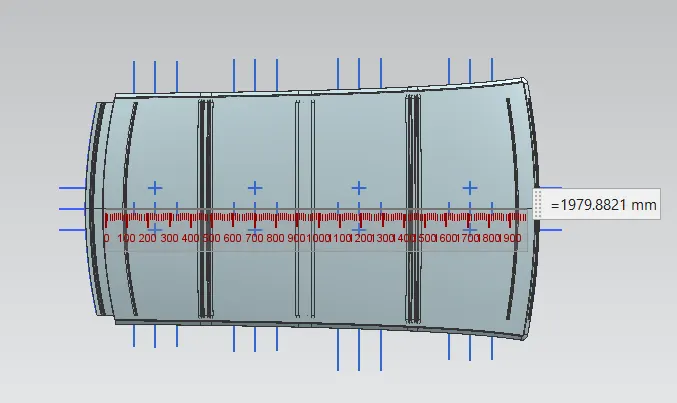
LX1Value:
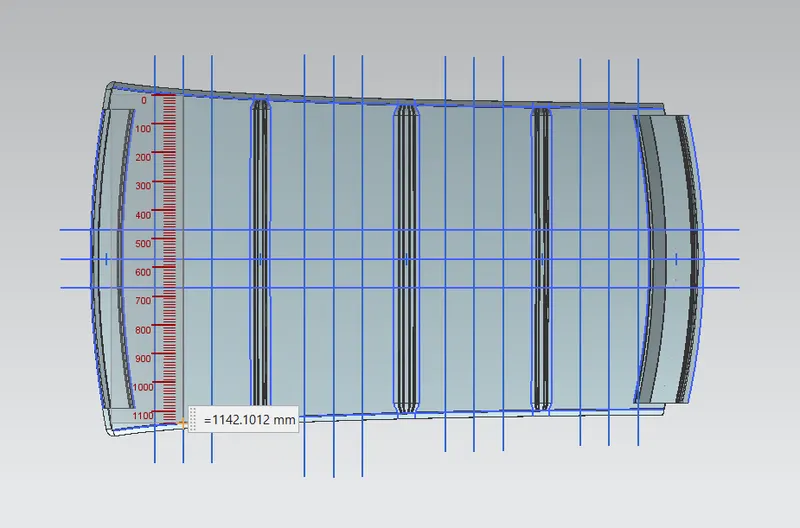
LX2Value:
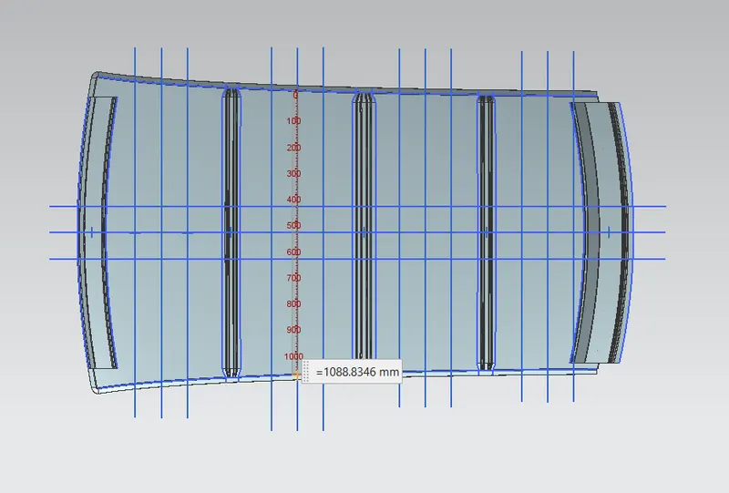
LX3Value:
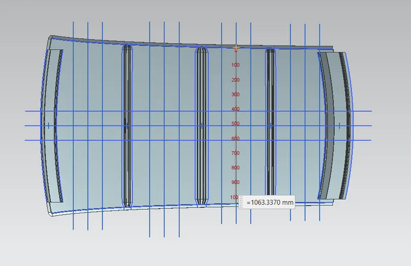
MOMENT OF INERTIA:
BOW ROOF RAIL 1:
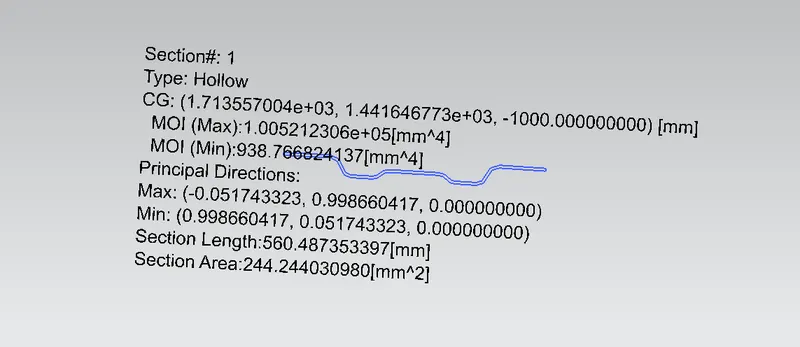
Therefore, we take the Minimum moment of inertia value is IY1 = 938.76 mm4.
BOW ROOF RAIL 2:
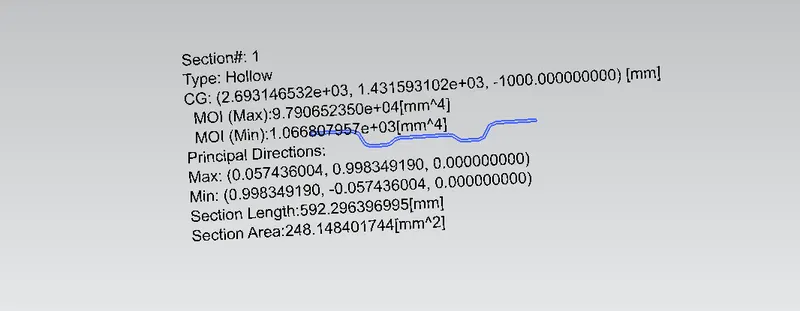
We take the Minimum moment of inertia value is IY2 = 1066.80mm4.
CENTER REINFORCEMENT ROOF RAIL:
We are taking the Hollow type for finding moment of inertia of the part. Therefore, reason is other two bow roofs are having solid structure. But center reinforcement roofs having the two solid part. So, that why we are joining to them and check for moment of inertia.
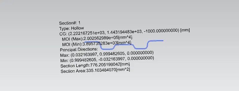
Minimum moment of inertia for center reinforcement roof rail is IY3 = 3895.73.4mm4
FINAL RESULTS OF SNOW LOAD CRITERIA:
We have the necessary values for finding the Snow load value(W):

If roof structure pass to the snow load condition. They, must have Qr values from above table.
Qr > 3.1
So, we done the curvature study on the roof. Heat distortion and snow load condition my roof is pass the two criteria, so position of the bow roofs and center reinforcement roofs placed at right area.
SECTION MODULUS:
The moment carrying capacity of an object is directly dependent on geometrical property (I) and material property (E) of an object, which is collectively termed as flexural rigidity (EI). Geometry of an object plays an important role in load bearing capacity of an object which is indicated by moment of inertia of a section.
Therefore, section modulus is the predominant factor which evidences the strength of an object and is defined as the ratio of the moment of inertia of the object about its centroidal axis to the distance of the extreme fibers of the object from the neutral axis.
There are two types of section modulus we have,
- Elastic section modulus
- Plastic section modulus
Elastic modulus is defined as,
S = I/Y
S – Section modulus,
I – Second moment of area
Y – distance from the neutral axis to outer most fiber of the object.
FRONT ROOF RAIL:
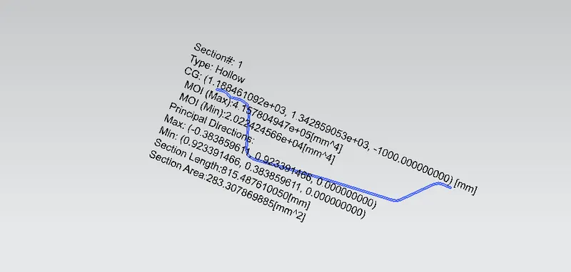
Moment of inertia (Max), Imax = 4.157 x 105 mm4
Moment of inertia (Min), Imin = 2.022 x 104 mm4
Section modulus = moment of inertia / distance between the neutral axis to extreme end of the object.
S = I/Y
Y = 54.72 mm
For maximum MOI,
S = 4.157 x 10⁵/54.72
SMAX = 7596.85 mm3
For minimum MOI,
S = 2.022 x 10⁴/54.72
SMIN = 369.51 mm3
BOW ROOF RAIL 1:
Moment of inertia (Max), Imax = 1.0052 x 105 mm4
Moment of inertia (Min), Imin = 938.76 mm4
Section modulus = moment of inertia / distance between the neutral axis to extreme end of the object.
S = I/Y
Y = 34.92 mm
For maximum MOI,
S = 1.0052 x 10⁵/34.92
SMAX = 2878.57 mm3
For minimum MOI,
S = 938.76/34.92
SMIN = 26.88 mm3
CENTER ROOF RAIL:
Moment of inertia (Max), Imax = 2.0025 x 105 mm4
Moment of inertia (Min), Imin = 3.8957 x 103 mm4
Section modulus = moment of inertia / distance between the neutral axis to extreme end of the object.
S = I/Y
Y = 44.46 mm
For maximum MOI,
S = 2.0025 x 10⁵/44.46
SMAX = 4504.04 mm3
For minimum MOI,
S = 3.8957 x 10³/44.46
SMIN = 87.62 mm3
BOW ROOF RAIL 2:
Moment of inertia (Max), Imax = 9.7906 x 104 mm4
Moment of inertia (Min), Imin = 1.0668 x 103 mm4
Section modulus = moment of inertia / distance between the neutral axis to extreme end of the object.
S = I/Y
Y = 34.92 mm
For maximum MOI,
S = 9.7906 x 10⁴/34.92
SMAX = 2803.72 mm3
For minimum MOI,
S = 1.0668 x 10³/34.92
SMIN = 30.54 mm3
REAR ROOF RAIL:
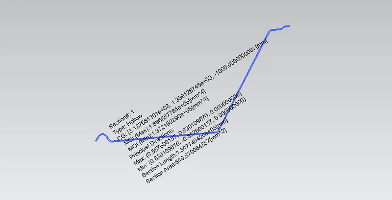
Moment of inertia (Max), Imax = 1.866857 x 105 mm4
Moment of inertia (Min), Imin = 1.37218 x 104 mm4
Section modulus = moment of inertia / distance between the neutral axis to extreme end of the object.
S = I/Y
Y = 95.17 mm
For maximum MOI,
S = 1.866857 x 10⁵/95.17
SMAX = 1961.60 mm3
For minimum MOI,
S = 1.37218 x 10⁴/95.17
SMIN = 144.18 mm3
DRAFT ANALYSIS:
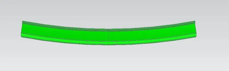
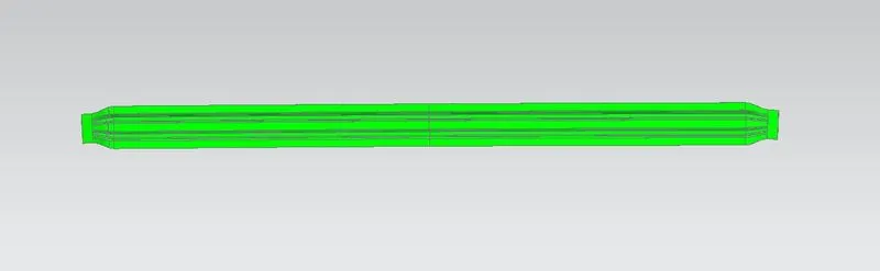
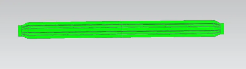
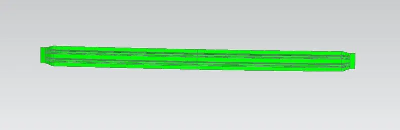
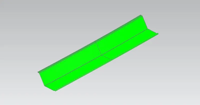
The Draft Analysis command enables you to detect if the part you drafted will be easily removed. This type of analysis is performed based on color ranges identifying zones on the analyzed element where the deviation from the draft direction at any point, corresponds to specified values.
Minimum draft angle is 7 degree is considered for analysis. Green colour show positive draft angle of the part more than 7 degree.
FRONT ROOF RAIL:
BOW ROOF 1:
CENTER ROOF RAIL:
BOW ROOF 2:
REAR ROOF RAIL:
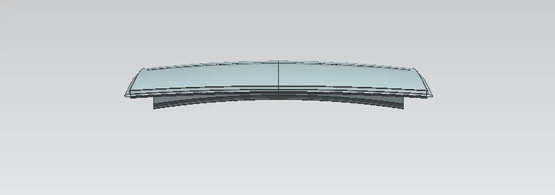
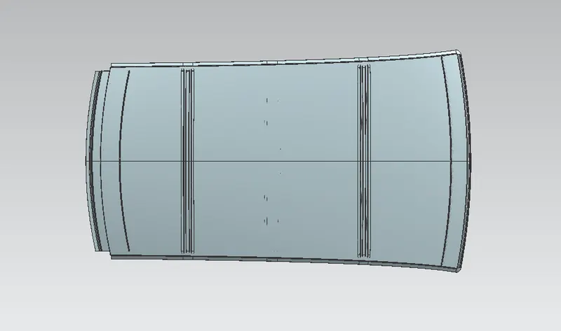
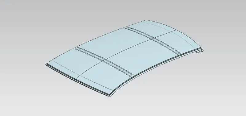
ROOF VIEWS:
FRONT VIEW:
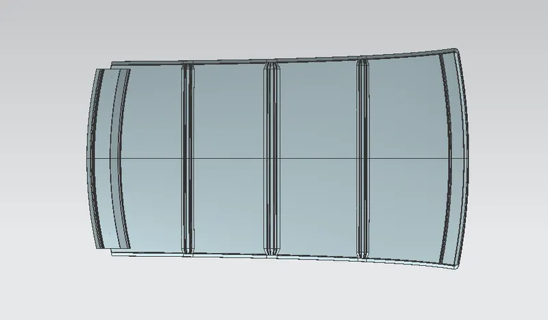
TOP VIEW:
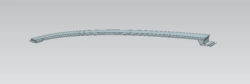
RIGHT SIDE VIEW:
BACK VIEW:
ISOMETRIC VIEW:
CONCLUSION:
I have designed my own roof and checked if bow roofs were positioned correctly by measuring heat distortion and snow load conditions. So, after completing my design, I tested it under the conditions of heat distortion and snow load. after, completing the curvature study i have checked section modulus and finally checked the draft analysis for the part can manuafacturable or not. After all test analysing my design pass all the requiremnts for placing the roof on the car.