Roof Design
INTRODUCTION:
A roof in a car typically refers to the top part of the car that covers the passenger compartment. It can be made of various materials such as metal, plastic, or fabric, and can be fixed or retractable. The roof provides protection from the elements and can contribute to the structural integrity of the vehicle.
The roof provides shelter and protection from the elements for the passengers inside. In some cars, the roof can be retractable or removable, allowing for an open-air driving experience.
OBJECTIVE:
1.Main objective of the project is to create the Roof Sheetmetal design in NX cad, and also designing Front roof rail, rear roof rail, bow roof front, bow roof rear, center roof rail and Reinforcement are creating to build the strong roof.
2.Do curvature study on Roof and performance calculations for Heat distortion and Snow load criteria to determine the position of the Bow roofs.
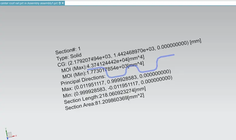
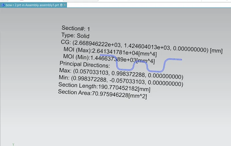
3.Finding the moment of inertia and section modulus for Bow-roofs and center roof rail.
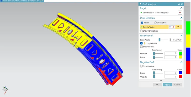
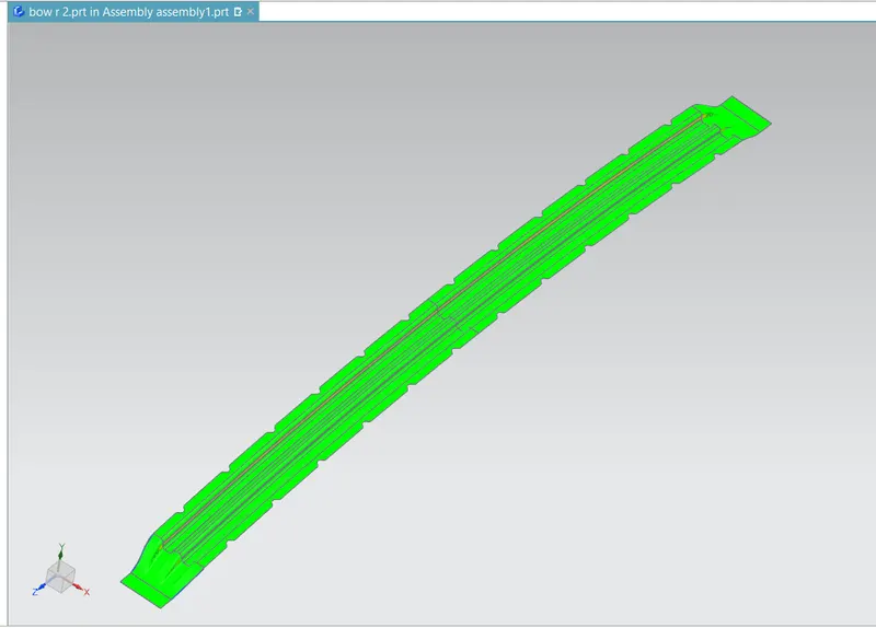
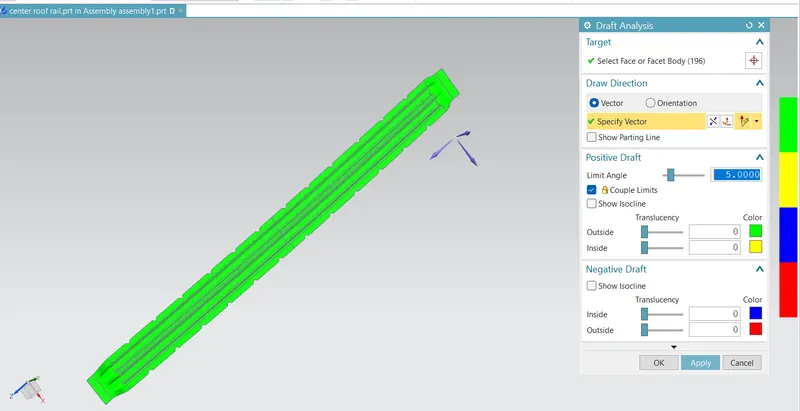
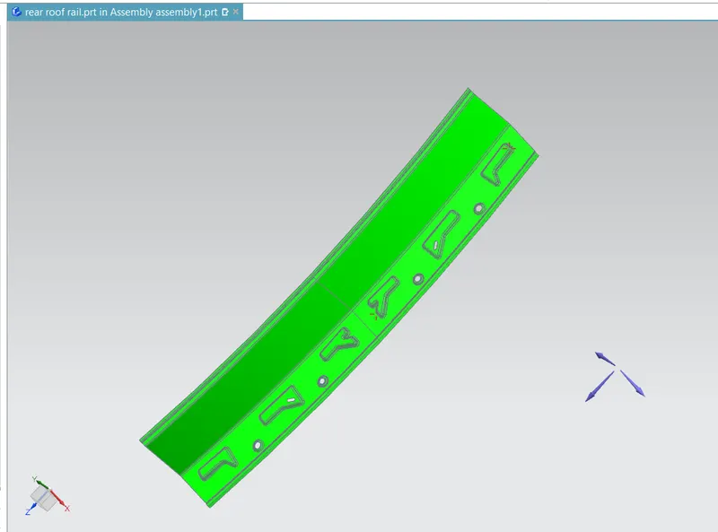
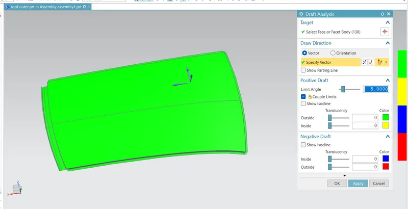
4.And, also finding the Draft Analysis of each part.
ROOF CRUSH TEST:
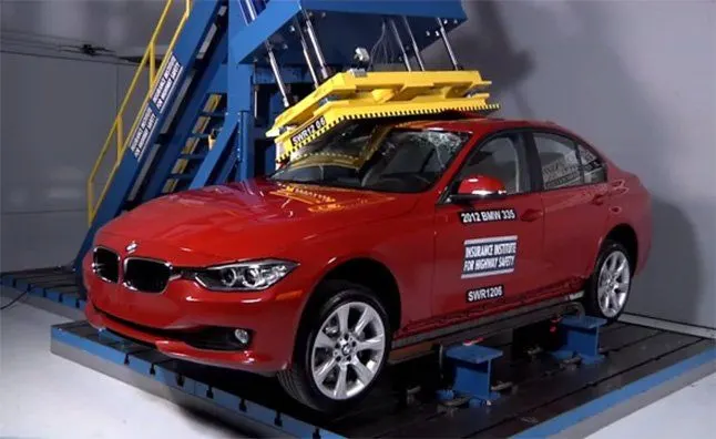
One of the tests used in occupant safety analysis is a roof crush test. It is used to evaluate how a car will deform during a rollover accident. A safer car does not deform as much providing the occupant a larger survival space during this kind of accident.
GOAL OF ROOF CRUSH TEST :
The roof crush test is conducted in cars to assess the structural integrity of the vehicle's roof and its ability to protect occupants during a rollover accident. A strong roof can prevent or minimize roof collapse and reduce the risk of serious injury or death in such an accident.
TESTING:
Roof strength evaluations are conducted on a quasi-static test system manufactured by MGA Research
Corporation (Figure).
The system consists of an upright assembly and an attached loading head that can be fixed at varying
heights from the ground and at pitch angles ranging from −5 to +5 degrees to accommodate testing on the
driver or passenger side.
The roll angle is permanently fixed at 25 degrees.
Four hydraulic actuators control the movement of the platen along two linear guides.
The entire system is mounted on a T-slot bed plate anchored to the floor of the test facility.
Figure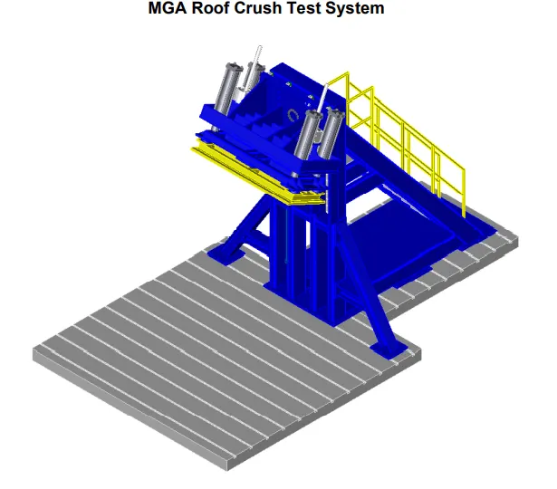
The load is applied in such a way that 50 is tilted from the front end to the rear end and the load will be in 1800 mm in length and 750 mm in width . The load is applied at the position of 250 from the flatness of the roof . The load is applied on the roof for almost 120 sec and the crush speed at which the load applied is 13 mm/sec. or less
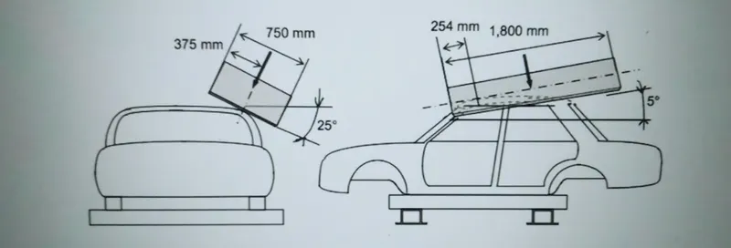
The displacement of the load application device is 127 mm or less when a load of 1.5 times the unloaded vehicle weight(N conversion value) is applied.
RESULTS :
If the displacements goes above the requirements level then we have to increase the bow roof thickness or add more mastics points to increase the strength . the stronger the roof the better it can protect the occupants in the roll over crashes.
HEAT DISTORTION:
Heat distortion in the roof of a car is a common problem that occurs due to prolonged exposure to high temperatures. When the metal roof of a car is heated, it expands, causing distortion in the surface. This distortion can result in visible waviness or rippling on the roof surface, making the car look unattractive.
The distortion in the roof may also lead to issues with the car's seals and cause water leakage. Over time, heat distortion can damage the roof, leading to more significant structural problems.
Bow–Roof Prediction Formula
W = [1.73 x 10^(-3) x L] + [1.85 x 10^(-8) x (R^2)/t] + [ 1.10x10^(-3) x l] - 2.68
Where,
L = Roof Length in X-Direction[mm](Roof dimension in 0-Y)
R = Roof curvature
R = 2(Rx*Ry)/(Rx+Ry)
Rx = X curvature
Ry = Y curvature
t = Roof plate thickness [mm]
l = Bow Roof Span [mm]
Judgment Condition
OK< 2.7
CALCULATIONS :
|
ROOF RAILS |
RX | RY | R | L | t | l | W | OK/NG |
| FR AND BR1 | 5725.45 | 2731.5 | 3698.51 | 2045.3 | 0.75 | 441.13 | 1.66 | OK |
| BR1 AND CR | 4885.52 | 6544.55 | 5594.64 | 2045.3 | 0.75 | 388.16 | 2.05 |
OK |
| CR AND BR2 | 3956.62 | 10682.59 | 5774.56 | 2045.3 | 0.75 | 413.44 | 2.12 | OK |
| BR2 AND RR | 3288.12 | 13978.21 | 5323.88 | 2045.3 | 0.75 | 334.3 | 1.91 | OK |
SNOW LOAD:
Snow load criteria study is used to check the durability of the roof to withstand the snow fall on the roof and reflex it is original shape without any permanent deformation after load being removed.
Snow Load Prediction Formula
Qr = [Iy x t2] / [α x s x [(Rx + Ry)/2]2 x 10-8]
Note: The Qr value given over here is correct. There was a typo error in the formula given in the video.
Where,
α = My x Lx2 x 10-12 , My = Y(Ly-Y)
t = Roof plate thickness [mm]
Ly = Distance between the front and rear roof Rails on the Vehicle along with 0Y[mm]
Length of Roof panel with the center point between Roof rail Front /Rear as the front and rear reference point.
Lx = Distance between the Left and Right end of the roof on the Roof BOW [mm]
The width of the roof panel is exposed on the surface.
Y = Distance front Front Roof Rail to Roof BOW[mm]
s = Distance for which Roof BOW bears divided load [mm]
s = L1/2 + L2/2
Iy = Geometrical moment of inertia of Roof BOW (Y cross-section )[mm4]
Rx = Lateral direction curvature radius of roof panel Y cross-section on Roof BOW [mm]
Roof panel curvature Radius of the Length Lx in Front view
Ry = Longitudinal Direction curvature radius of the Roof panel X cross-section on Roof BOW [mm]
Roof panel X curvature radius of length s in Side view
Judgment condition
Qr ≥ 3.1
250 ≤ s ≤ 380
CALCULATION:
|
ROOF RAIL |
IY (mm^4) |
LX (mm) |
LY (mm) |
L1 (mm) |
L2 (mm) |
RX (mm) |
RY (mm) |
t (mm) |
Y (mm) |
S (mm) |
My (mm) |
α | Qr | OK/NG |
| FR AND BR1 | 1.42 | 1103.00 | 1944.4 | 533.75 | 464.83 | 4416.54 | 2767.86 | 0.75 | 533.75 | 499.29 | 752935.84 | 0.91 | 20.06 | OK |
| BR1 AND CR | 1.77 | 1069.47 | 1944.4 | 464.83 | 489.95 | 3784.00 | 6468.25 | 0.75 | 998.58 | 477.39 | 944476.93 | 1.08 | 8.07 | OK |
| CR AND BR2 | 1.44 | 1049.59 | 1944.4 | 489.95 | 455.87 | 4283.80 | 11206.56 | 0.75 | 1488.54 | 472.91 | 678565.84 | 0.74 | 5.21 | OK |
SECTION MODULUS:
BR1
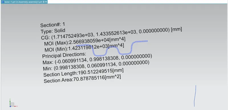
CR
BR2
DRAFT ANALYSIS:
FRONT ROOF RAIL:
BR1
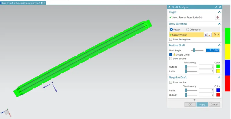
BR2
CR
RR
ROOF OUTER
CONCLUSION :
Hence the roof, front roof rail, bow roof rails, center roof rail and the rear roof rail is designed by following the master section and the moment of inertia, section modulus and draft analysis are carried out to check feasibility manufacturing.