Roof Design
Roof Design
Objective:
The object of this design is to design a roof with it’s components such as front roof rail, rear roof rail, and bow roofs by following the given master sections.
The parts of roof are:
1)Outer roof
2)Front roof rail
3)Front bow roof rail
4)Middle bow roof rail
5)Rear bow roof rail
6)Rear roof rail
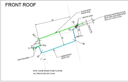
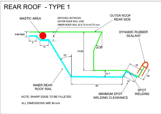
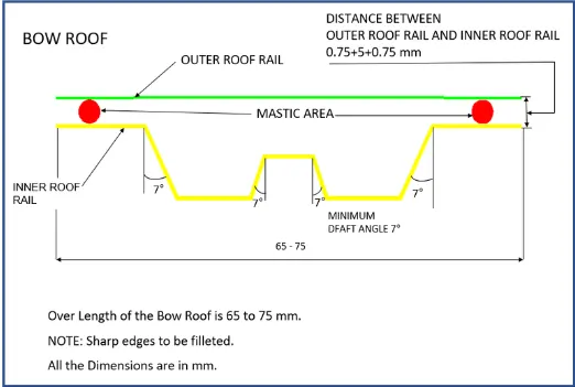
Master sections for each rail are given below:
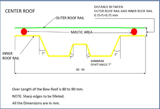
Front roof rail:
Front roof rail acts as a joining member for outer roof panel and wind shield.
It also plays crucial part in case of impact.
It protects occupants from major head injury in case of impact up to certain limit.
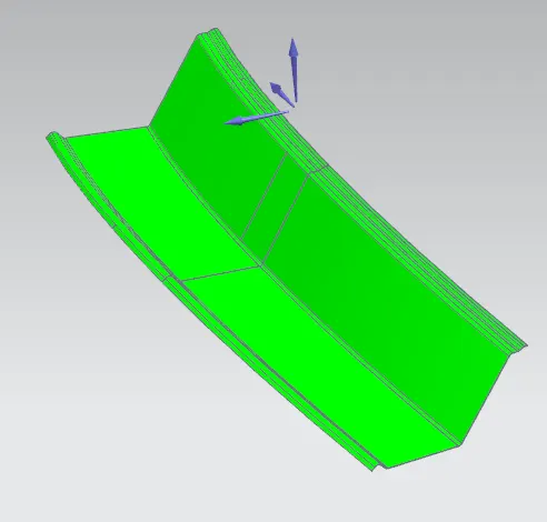
The image of front roof rail:
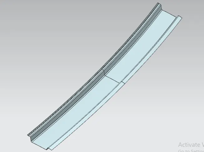
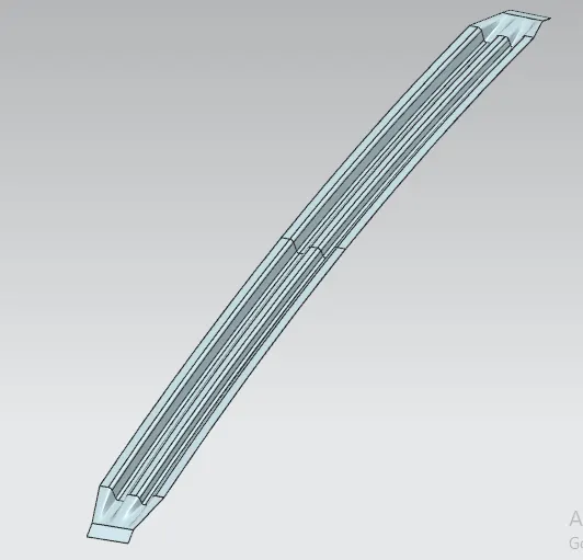
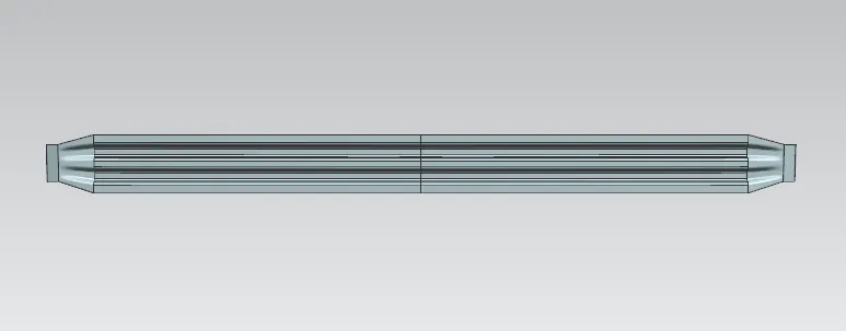
Front, middle, rear bow rail:
These bow rails act as a support and reinforcement at a time of an impact. These rails provide strength for outer roof panel and support function as a additional support.
Outer roof:
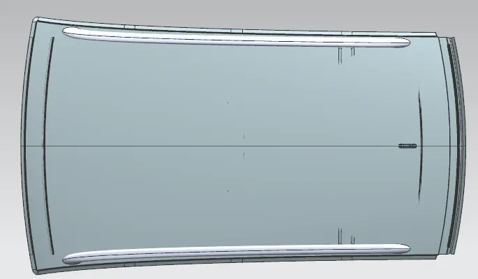
It provides aesthetic view and primary protection to the cabin occupants from an impact and protects from isolates them from surrounding environment.
Heat Distortion calculation:
Heat distortion temperature is the temperature at which the metal softens and deforms under a specific load. This study is done to check the ability of the roof to withstand high temperatures concerning the positioning of the reinforcements which contribute to increased strength.
Procedure:
Create a center line at the 0-Y region of the roof and then offset the same to -3Y.
Create a symmetric line from the -3Y region at a distance of 100mm.
Draw a vertical line at the midpoint of the line drawn from the center points of the FRR and BR 1 and followed the same till the rear roof rail.
Offset the vertical line to a distance of 100mm on each side.
Create intersection points and project them on the roof.
From these projected points, make a 3-point arc and the Rx and Ry values.
Formula for Heat Distortion criteria check:

where,
L = Roof Length in X-Direction[mm](Roof dimension in 0-Y)
R = Roof curvature
R = 2(Rx*Ry)/(Rx+Ry)
Rx = X curvature
Ry = Y curvature
t = Roof plate thickness [mm]
l = Bow Roof Span [mm]
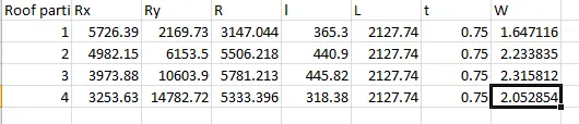
Value of W should be less than 2.7.
In below table the values of W for different region of roof are given and it satisfies the criteria.
After completing that snow load criteria is also checked for the roof.
Snow load criteria:
A snow load study is done to check the ability of the roof to withstand snowfall and come back to its original position without undergoing permanent deformation upon the removal of the snow load.
Procedure:
Create a center line at the 0-Y region of the roof and then offset the same to 100mm on each side.
Draw a vertical line at the midpoint of the line drawn from the center points of the FRR and BR 1 and followed the same till the rear roof rail.
Offset the vertical line to a distance of 100mm on each side.
Create intersection points and project them on the roof.
From these projected points, make a 3-point arc and the Rx and Ry values.
Project the extreme edges of the styling surface fro measuring the width at the respected sections.
The formula for snow load calculation is given below:

where,
α = My x Lx2 x 10-12 , My = Y(Ly-Y)
t = Roof plate thickness [mm]
Ly = Distance between the front and rear roof Rails on the Vehicle along with 0Y[mm]
Length of Roof panel with the center point between Roof rail Front /Rear as the front and rear reference point.
Lx = Distance between the Left and Right end of the roof on the Roof BOW [mm]
The width of the roof panel is exposed on the surface.
Y = Distance front Roof Rail to Roof BOW[mm]
s = Distance for which Roof BOW bears divided load [mm]
s = L1/2 + L2/2
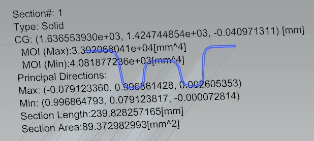
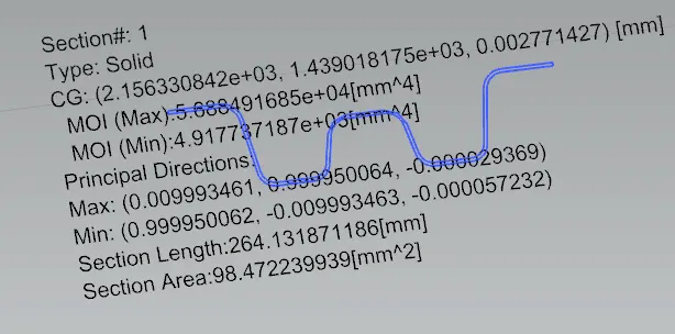
Iy = Geometrical moment of inertia of Roof BOW (Y cross-section )[mm4]
Rx = Lateral direction curvature radius of roof panel Y cross-section on Roof BOW [mm]
Roof panel curvature Radius of the Length Lx in Front view
Ry = Longitudinal Direction curvature radius of the Roof panel X cross-section on Roof BOW [mm]
Roof panel X curvature radius of length s in Side view
Images for snow load calculation are given below:

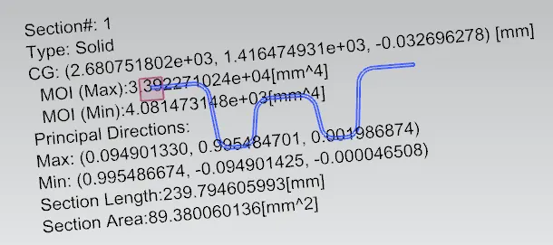
Images for moment of inertia for different section are given below:
Draft analysis:
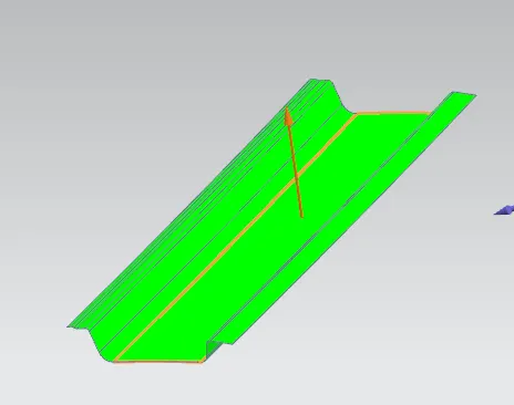
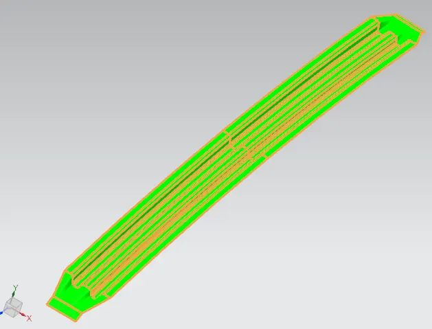
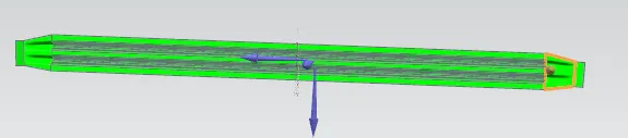
Draft analysis is necessary to check whether the sheet metal part is compatible or not for manufacturing.
General criteria for the draft angle is 7˚.
Images of different part draft analysis are given below:
Front roof rail:
Front bow rail:
Middle bow rail:
Rear roof rail: