Roof Design
INTRODUCTION
An automobile roof or car top is the portion of an automobile that sits above the passenger compartment, protecting the vehicle occupants from sun, wind, rain, and other external elements.
When it is seen from the outside of the car, it is just closing the top portion. But from a design point of view, it is hard to create the design. Because you have to create no support rails for enough strength to withstand the load. Bow roofs are primarily fixed in flatter regions to enhance strength.
Front and rear roof rails are fixed to the ditch area using spot weld operation. But the front and rear bow roof, and center roof rails are fixed to the roof using mastic sealants. We don’t want so many gaps between the roof rails and the bow roof area. We are reducing NVH issues.
OBJECTIVE:
- The main objective of the project is to create the Roof Sheet metal design in catia v5, and also design the Front roof rail, rear roof rail, bow roof front, bow roof rear, center roof rail, and Reinforcement are creating to build a strong roof.
- Do curvature study on Roof and performance calculations for Heat distortion and Snow load criteria to determine the position of the Bow roofs.
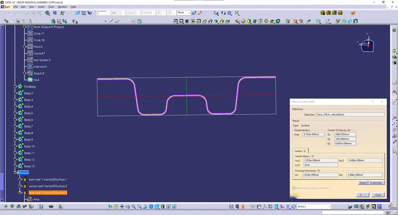
- Find a moment of inertia and section modulus for bow roofs and central roof rails.
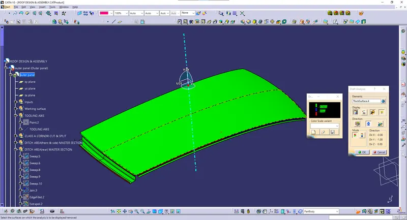
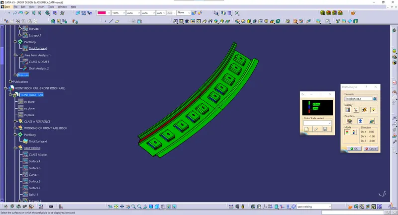
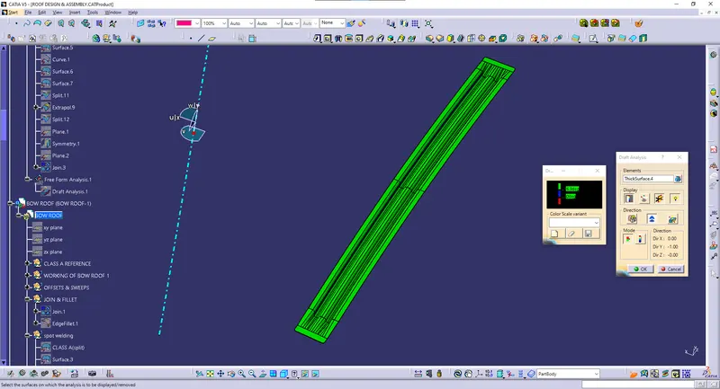
- Find the Draft Analysis for each part.
METHODOLOGY
We got the model of the roof from the styling team. Then we will have to do all the engineering work. We created a ditch area for the roof and also roof bows and roof rails for the roof which would be designed by us considering all safety norms and regulations.
DESIGN CONSIDERATION-
- Visibility criteria
- Head clearance
- Curvature study
- Hear distortion and snow load criteria
- Draft analysis.
Master section for the roof-
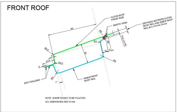
Front Roof Rail Master section
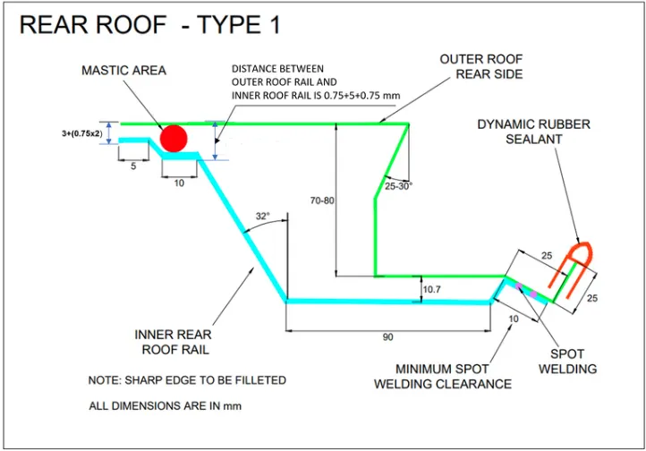
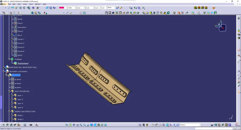
Master section of the Rear Roof Rail
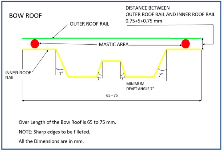
Master section of Bow Roof
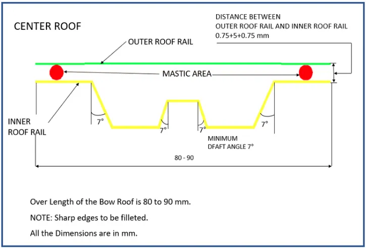
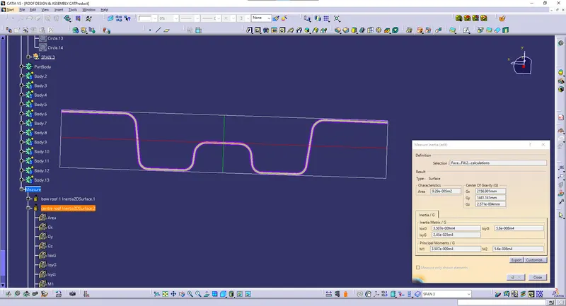
Master section of Center Reinforcement Rail
Components of the roof-
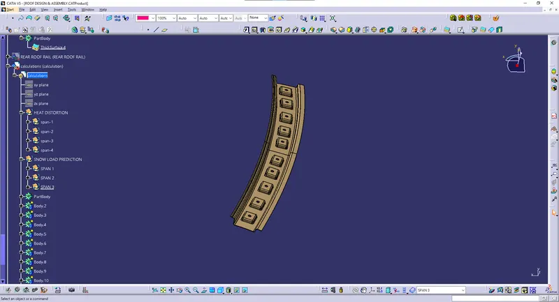
1. Front Roof Rail-
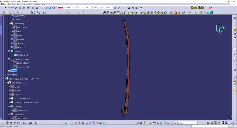
The front roof rail is located on the front of the roof where the windshield joins with the roof. The visibility criteria and the headroom clearance of the passenger are taken into consideration for the bottom flange. One end of the rail is joined using spot welding while the other end is joined with the roof using mastic sealants for increased strength.
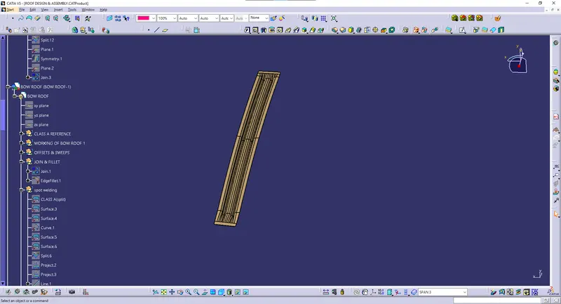
2. Bow roof 1-
A bow roof is an additional stiffening member for the roof to increase its strength so that it can satisfy the norms. Both ends are joined together using mastic sealants to increase strength and also since this would not affect the styling of the roof.
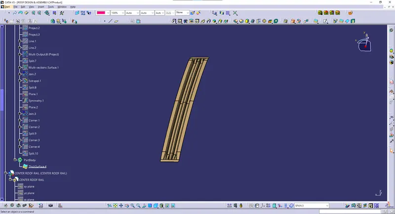
3. Centre Roof Rail-
The Centre Roof rail or the reinforcement center is located at the center of the roof. The cross-section of this is more since it needs to provide more strength to the roof. Here both ends are joined together using mastic sealants.
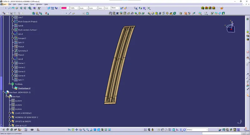
4. Bow roof 2-
This bow roof also has the same purpose as that of the first one. This one is located between the center bow roof and the rear roof rail.
5. Rear Roof Rail.
This roof rail joins with the back door and the roof. Inputs from the backdoor are taken into consideration for designing this roof rail.
Here one end is joined using spot welding while the other end is joined using mastic sealants.
Bow – roof prediction Formula
W = [1.73 x 10^(-3) x L] + [1.85 x 10^(-8) x (R^2)/t] + [ 1.10x10^(-3) x l] - 2.68
Where
L = Roof Length in X-Direction[mm](Roof dimension in 0-Y)
R = Roof curvature
R = 2(Rx*Ry)/(Rx+Ry)
Rx = X curvature
Ry = Y curvature
t = Roof plate thickness [mm]
l = Bow Roof Span [mm]
Judgement Condition : OK< 2.7> 3.1
SNOW LOAD CRITERIA :
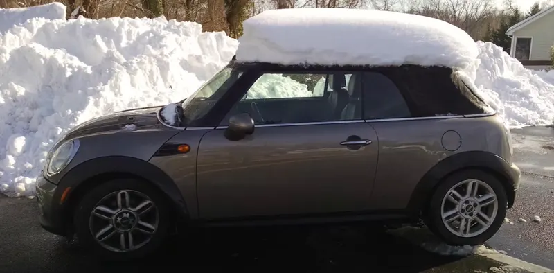
This test is done to know how is the roof behaving when there is a snow over . normally due to the snow weight the dent will happen. But the roof should be designed in such a way that when the snow is removal the roof should go it its original position . This is the basic requirements for snow load criteria .
Qr = [Iy x t2] / [α x s x [(Rx + Ry)/2]2 x 10-8]
Where
α = My x Lx2 x 10-12 , My = Y(Ly-Y)
Judgement condition = Qr ≥ 3.1
250 ≤ s ≤ 380
t = Roof plate thickness [mm]
Ly = Distance between the front and rear roof Rails on the Vehicle along with 0Y[mm]
Length of Roof panel with the center point between Roof rail Front /Rear as the reference point of the front and the rear.
Lx = Distance between the Left and Right end of the roof on the Roof BOW [mm]
Width of the roof panel exposed on the surface.
Y = Distance front Front Roof Rail to Roof BOW[mm]
s = Distance for which Roof BOW bears divided load [mm]
s = L1/2 + L2/2
Iy = Geometrical moment of inertia of Roof BOW (Y cross-section )[mm4]
Rx = Lateral direction curvature radius of roof panel Y cross-section on Roof BOW [mm]
Roof panel curvature Radius of the Length Lx in Front view
Ry = Longitudinal Direction curvature radius of the Roof panel X cross-section on Roof BOW [mm]
SECTION MODULUS :
Section modulus is a geometric property for a given cross-section used in the design of beams or flexural members. Other geometric properties used in design include area for tension and shear, radius of gyration for compression, and moment of inertia and polar moment of inertia for stiffness. Any relationship between these properties is highly dependent on the shape in question. Equations for the section moduli of common shapes are given below.
There are two types of section moduli :
The elastic section modulus and
The plastic section modulus.
The elastic section modulus is defined as
S = I / y
where :
S= Section modulus
I = second moment of inertia (or area moment of inertia, not to be confused with moment of inertia)
y = the distance from the neutral axis to any given fibre. It is often reported using y = c, where c is the distance from the neutral axis to the most extreme fibre
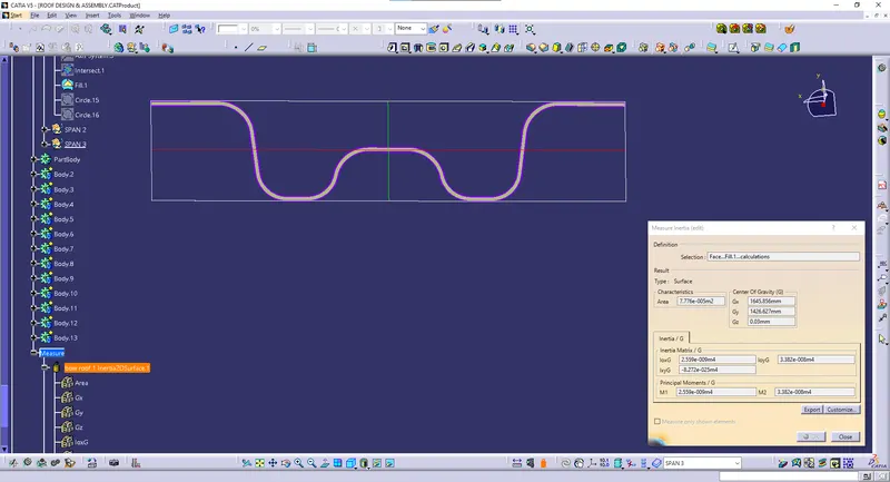
BOW ROOF 1
Create an intersection curve with the help of the plane and select the bow roof 1
CENTRE ROOF RAIL
BOW ROOF 2
DRAFT ANALYSIS
Outer panel draft analysis
Front roof rail draft analysis:
Bow roof 1 draft analysis
Centre roof rail daft analysis
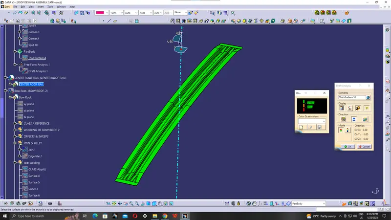
Bow roof 2 draft analysis
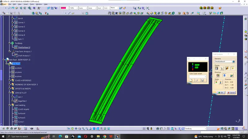
Rear roof rail draft analysis
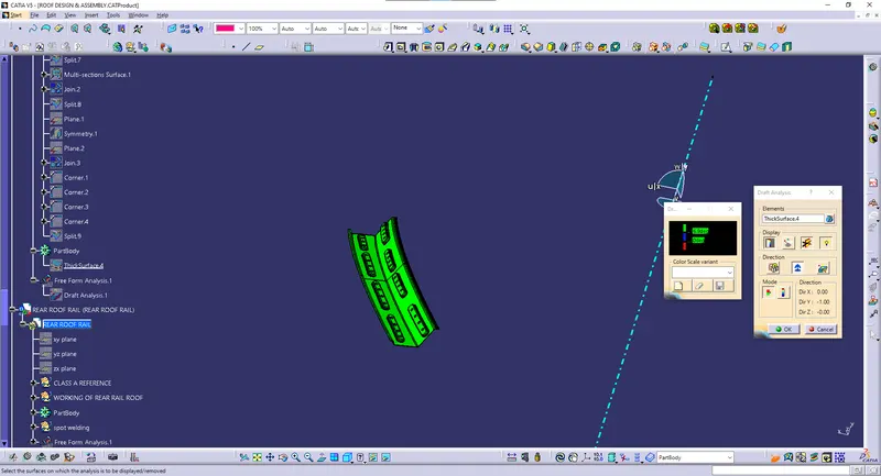
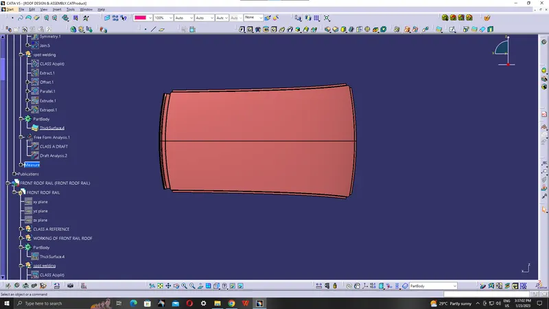
Roof Images
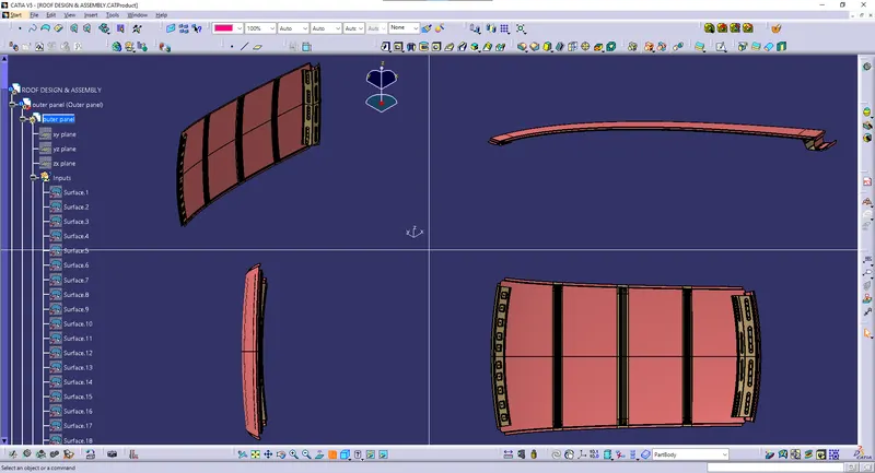
Top view
Side view
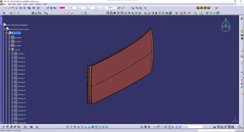
Isometric view
CONCLUSION
Hence the roof , front roof rail, bow roof rails , central roof rail and the rear roof rail is designed by following the master sections. The position of the bow roofs which was designed is good for manufacturing.