Roof Design
ROOF DESIGN
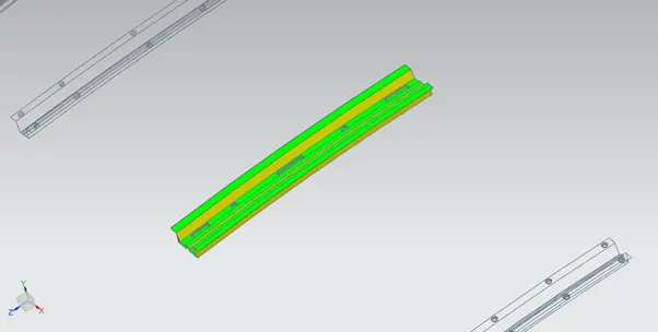
An automobile roof or car top is the portion of an automobile that sits above the passenger compartment, protecting the vehicle occupants from sun, wind, rain, and other external elements.Roof is the top most covering provided for the vehicle and for safety side it’s important for roll over kind of accidents, which the basic test performed for safety purpose. In order to give strength, it is provided with embosses on top of the roof.
FRONT ROOF RAIL
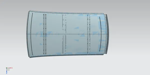
- Front roof rail is one of the important parts in the inner panel of the roof for proper strength and rigidity.
- Front roof rail is the most important commodity which give as reinforcement and has mounting features like bracket map lamp and room lamp.
- Proper care has been taken to provide space for welding and part joining.
- For additional strength, embosses are been provided.
REAR ROOF RAIL
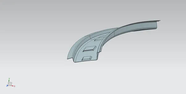
- Rear roof rail is similar to the front roof rail.
- Rear headroom and rear visibility criteria are considered and also tailgate will be mounted on the rear roof rail, so tailgate conditions have to be considered while designing the rear roof rail.
BOW ROOF RAIL
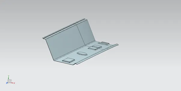
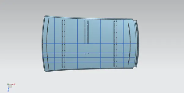
- Bow roof is been provided for additional strength especially against snowing condition and rollover situation.
- Bow roof rails are provided for the support of the roof surface.
- The bow roofs are provided with mastic sealant as they are assembled with the surface as welding is not possible, whereas the ditch area, front and rear area is welded with the roof.
- Bow roof 1 and bow roof 2 are provided for better protection of roof from crash.
- Front and rear bow roofs are provided with optimal angle of inclination to meet the production criteria (positive draft angle) and visibility criteria.Mounting of windshield and rear glass becomes easier.
CENTRE ROOF RAIL
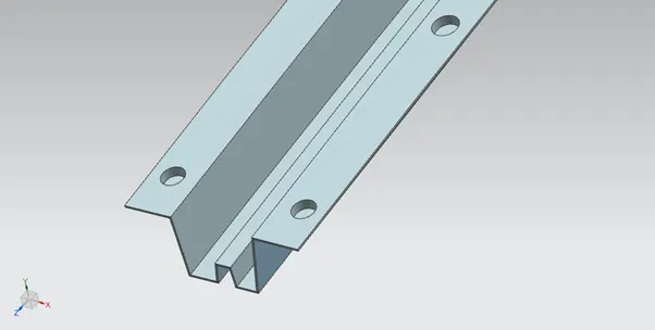
- Centre roof rail is attached to the roof by a spot welding method.
- It can be added as per required strength of the car.
- Centre roof rail has two layers(reinforcement) as to protect it from roll over crash.
DITCH AREA
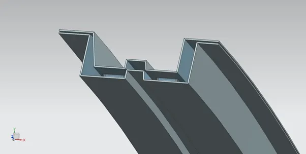
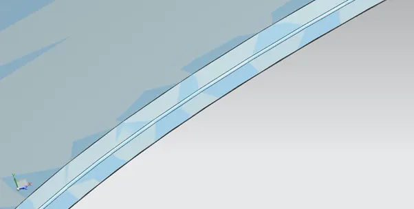
- Ditch area is been provided on all the four sides of the roof.
- Roof ditch areas are provided to mount roof to the main body of the car also to mount windshield glass for the front ditch area, and to mount tailgate to rear ditch area.+
ROOF BOW CALCULATIONS
Heat distortion criteria
It is the temperature at which the material starts softening when exposed to a fixed load at elevated temperature. Above this temperature the material can’t be used. In order to know whether the material is in safer zone according the positioning of bow roofs, the test is performed by considering the below given formula –
W = [1.73 × 10^(-3) × L] + [1.85 × 10^(-8) × (R^2)/t] + [ 1.10x10^(-3) × l ] - 2.68
L = Roof Length in X-Direction [mm] (Roof dimension in 0-Y)
R = Roof curvature
R = 2(Rx*Ry) ÷ (Rx+Ry)
Rx = X curvature
Ry = Y curvature
t = Roof plate thickness [mm]
l = Bow Roof Span [mm]
Judgment Condition:
OK< 2.7 <NG
|
Sr. No |
BOW |
Rx |
Ry |
R |
t |
I |
L |
W |
OK /NG |
|
1 |
FRR&1st |
5711 |
2423 |
3402 |
0.75 |
328 |
2032 |
1.47 |
OK |
|
2 |
1st&CRR |
4963 |
5615 |
5268 |
0.75 |
419 |
2032 |
1.97 |
OK |
|
3 |
CRR&2nd |
4000 |
11095 |
5880 |
0.75 |
552 |
2032 |
2.28 |
OK |
|
4 |
2nd&RRR |
3263 |
16754 |
5462 |
0.75 |
284 |
2032 |
1.44 |
OK |
Since all values are less tha 2.7 bow positions are correct.Design passes heat distortion test.
Snow load test
It is used for checking whether the roof can withstand snow load and come back to orginal position after deformation when load is removed.
Qr = [Iy x t^2] / [α x s x [(Rx + Ry)/2]^2 x 10-8]
Where,
α = My x Lx^2 x 10^-12 , My = Y(Ly-Y)
t = Roof plate thickness [mm]
Ly = Distance between the front and rear roof Rails on the Vehicle along with 0Y[mm]
Length of Roof panel with the center point between Roof rail Front /Rear as the front and rear reference point.
Lx = Distance between the Left and Right end of the roof on the Roof BOW [mm]
The width of the roof panel is exposed on the surface.
Y = Distance between front Front Roof Rail to Roof BOW[mm]
s = Distance for which Roof BOW bears divided load [mm]
s = L1/2 + L2/2
Iy = Geometrical moment of inertia of Roof BOW (Y cross-section )[mm4]
Rx = Lateral direction curvature radius of roof panel Y cross-section on Roof BOW [mm]
Roof panel curvature Radius of the Length Lx in Front view
Ry = Longitudinal Direction curvature radius of the Roof panel X cross-section on Roof BOW [mm]
Roof panel X curvature radius of length s in Side view
Judgement condition:
Qr ≥ 3.1
250 ≤ s ≤ 380
|
S.No |
BOW |
Iy |
α |
Lx |
Ly |
y |
s |
Rx |
Ry |
t |
Qr |
OK |
|
1 |
FRR&1st |
954.69 |
0.67 |
1070 |
1888 |
396 |
509 |
4165 |
8595 |
0.75 |
3.86 |
OK |
|
2 |
1st&CRR |
950.63 |
0.91 |
1080 |
1888 |
623 |
556 |
4003 |
4599 |
0.75 |
5.71 |
OK |
|
3 |
CRR&2nd |
976.88 |
0.83 |
1105 |
1888 |
489 |
432.5 |
3359 |
5480 |
0.75 |
7.59 |
OK |
|
4 |
2nd&RRR |
- |
- |
- |
- |
- |
- |
- |
- |
- |
- |
- |
Since all value are greater than 3.1 design is safe.
DRAFT ANALYSYS
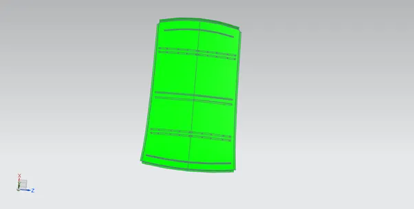
Minimum draft angle of 7* considered for analysys.
OUTER ROOF
FRONT ROOF RAIL
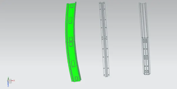
REAR ROOF RAIL
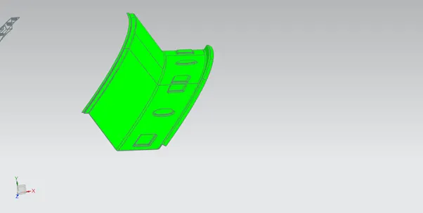
BOW ROOF RAIL 1
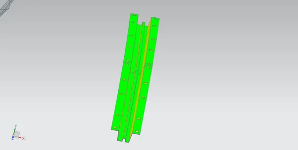
BOW ROOF RAIL 2
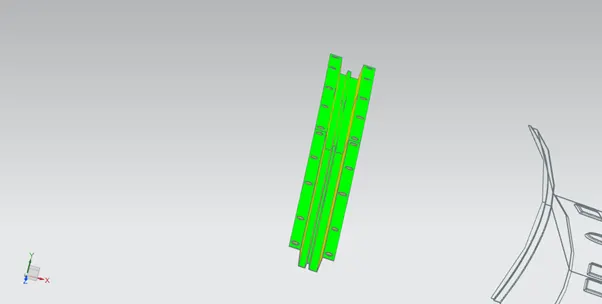
CENTRE ROOF RAIL