Roof Design
ROOF DESIGN
Objective :
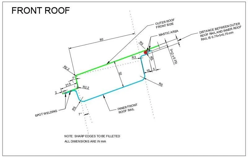
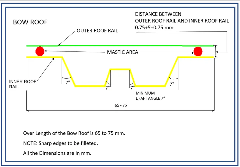
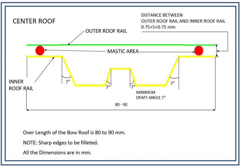
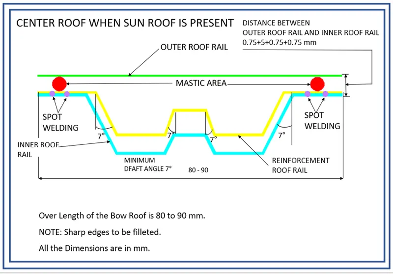
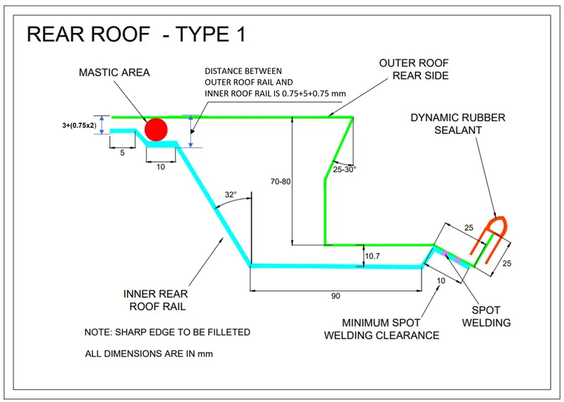
- To design a sheet metal Roof with it’s reinforcement structures, i.e. Front Roof Rail, Rear Roof Rail, Front Bow Roof Rail, Center Roof Rail and Rear Bow Roof Rail, according to the required standards from the Master Sections.
- Do a curvature study on roof by calculating the Heat-Distortion and Snow-Load criteria to determine the position of the Bow Roof Rails.
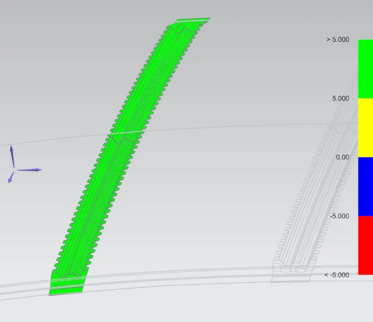
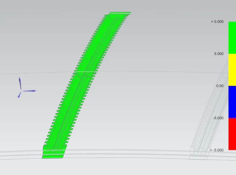
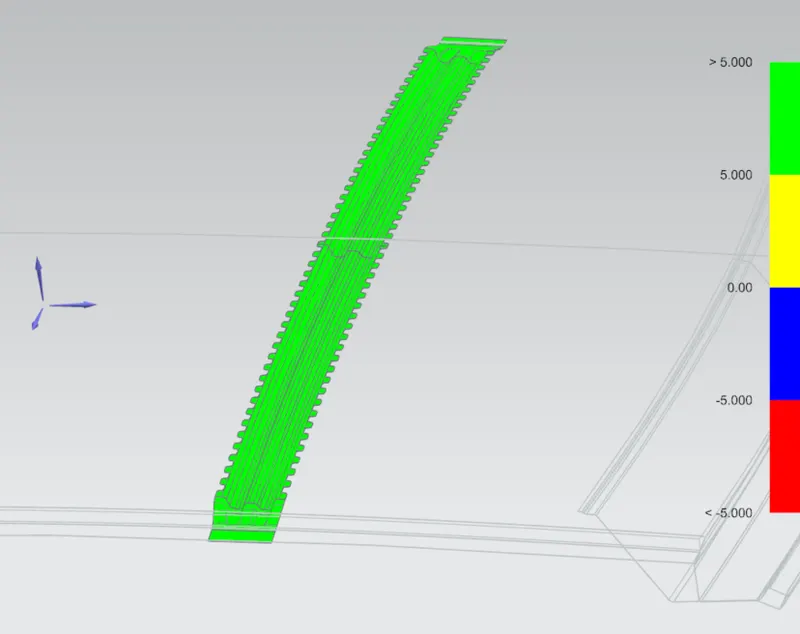
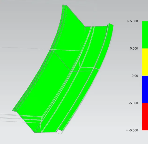
- Do a Draft Analysis on each part of the Roof.
Software Used :
Seimens NX 12.0
Master Sketch :
Introduction :
The roof of a car or an automobile is the portion that covers the top of interior compartment acting as a ceiling of the vehicle. It protects the interior of the vehicle rain, keeps the sun and other environmental elements away from the passengers and interior components. The roof is joined to the car at the A, B & C pillars with Front, Center & Rear Roof Rails respectively. Bow Roof Rails are the reinforcements provided to the roof in between the other Rails.
Roofs can be fitted with extra accessories like roof racks and luggage carriers, thus improving is usability but reduces the aerodynamics of the car.
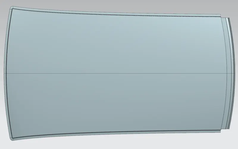
Top view of a Car Roof
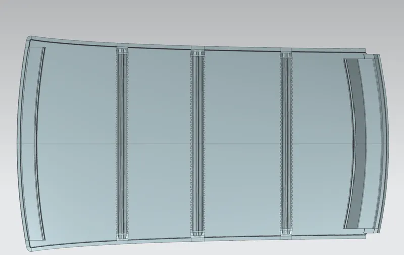
Bottom view of a car Roof
Components of a roof are :
- Front Roof Rail (FRR)
It gets welded onto the A-pillar of the car. Provides support area for windshield placement. Must be designed in such a way that it doesn’t impede the front visibility criteria for the driver and passengers. Embosses and darts are used to further strengthen this component. The allowances for sealants, glues and other materials are to be considered before final design.
Thickness, t = 0.75mm.
Emboss height, h =2< h <3t.
- Center Roof Rail (CRR)
It gets welded onto the B-pillar of the car. It is most susceptible to failure due to external load.
- Rear Roof Rail (RRR)
Created at the rear end of the car and gets welded onto the C-pillar of the car. The backdoor (boot) of the car is fitted on to this reinforcement component. The headroom clearance (>120mm), placement of rubber weather sealants, etc. needs to be taken into consideration during it’s design. Embosses and darts are provided for further strengthening of the part.
Thickness, t = 0.75mm.
Emboss height, h =2< h <3t.
- Bow Roof Rails (BRR)
A roof design requires at least two BRRs. BRR-1 is provided in between the FRR & CRR and BRR-2 is placed between CRR & RRR. They are the main reinforcement component of the car roof and the no. of BRRs can be increased if need be, which depends on the length of the car roof. It’s placement is determined after conducting the curvature study of the roof.
- Ditch Area
It’s the extended portion of the roof which is concealed by the outer panels. The roof rails are spot welded onto the roof at the ditch area (length of 15-20mm, with 3 degrees of positive draft).

Functions :
- Roof -
- Protection from weather, rain, sun and other environmental elements.
- Safety from crashes, rolls and other accidents.
- Provides area for mounting interior lights and components needed for the passenger’s convenience.
- Roof Rails -
- Provides structural rigidity to the roof.
- Provides stiffness the car skeleton/body.
Design Requirements :
- Head-room clearance at the front ( >120mm) and rear (>80mm) of the car.
- Visibility criteria for the driver.
- Enough area for interior lamp mounts, sun shades and other convenience components.
- Positions of the A, B & C pillars of the car.
- Heat distortion and Snow load criteria.
- Presence of Sun-roof/Moon-roof.
- Roofs need to be completely sealed to prevents leaks due to different weather, this can be done using rubber seals.
- The gaps should minimum to zero between roof and the rest of the car body.
- All designs must follow the master sections provided and take the roof surface as reference.
Types :
- Flat Roof
Car roofs that covers the whole top part and is fixed permanent to the body.
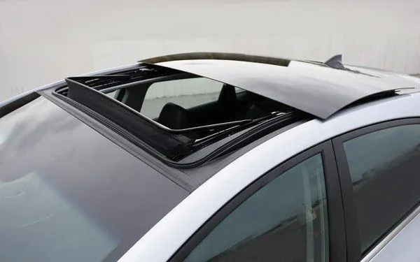
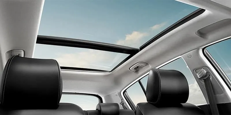
- Sun-roof/Moon-roof
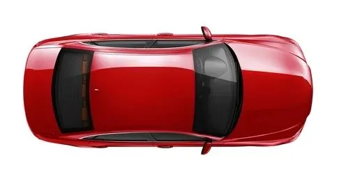
Roofs with partially removable parts on them are sun-roof, they can be either opaque or made with tinted-laminated glass. Moon-roofs are permanently fixed and is completely made tinted glass.
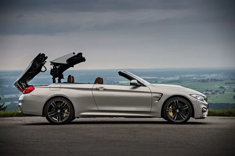
- Convertibles
Roofs that can be completely removed to allow the car to be converted from with-roof to without-roof.
Safety Tests :
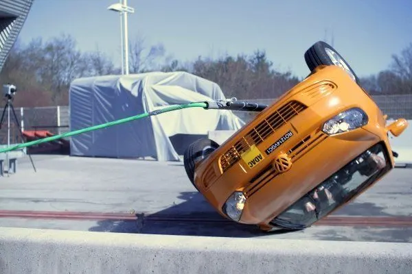
- Roll Over Test -
It’s conducted with taking the total weight (curb weight + passenger weight + weight of any luggage if present) of the car, with the headroom criteria included. The total deformation with respect to the initial condition is compared.
- Roof Crush Test -
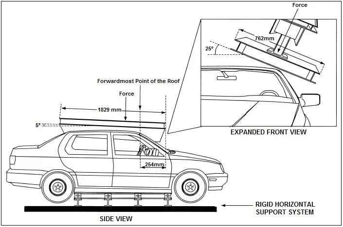
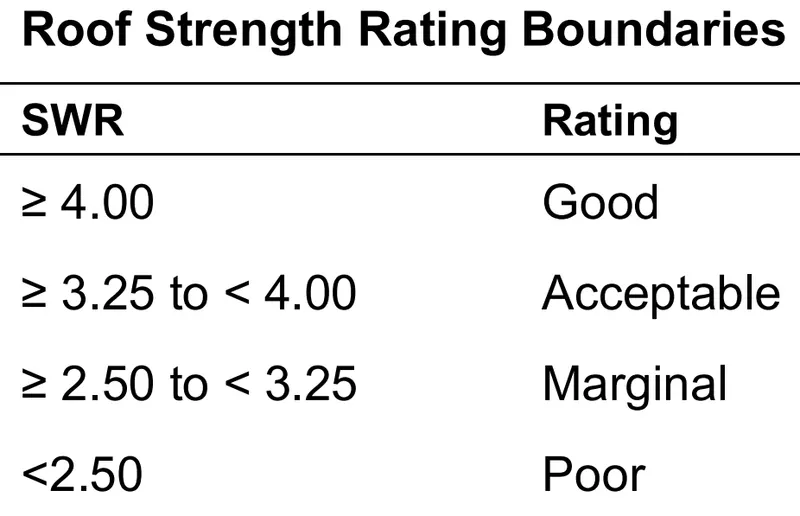
It’s conducted only taking the curb weight (car weight+fuel weight) of the car, without including the headroom criteria. The test is set as shown in the image below and the force is gradually increased. The amount of force that the roof can withstand without getting a permanent deformation is noted and the force that negates the headroom clearance of the roof due to deformation is also noted. The strength to weight ratio (SWR) is calculated.
Manufacturing Techniques :
- Deep Drawing
The Embosses, Ditch areas and Roof Rails are deep drawn.
- Mastic seals
Mastic points are provided on all the Roof Rails to stiffen and strengthen the components.
- Spot Welding
The components are connected to the body with spot welding at the ditch area, these parts are hidden with outer panels and other components.
- Punching
Holes required for adding and connecting different components in the car are provided on the reinforcements using hole punch techniques.
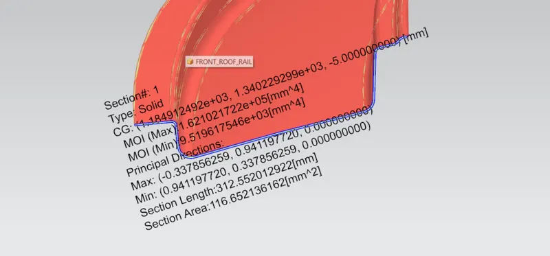
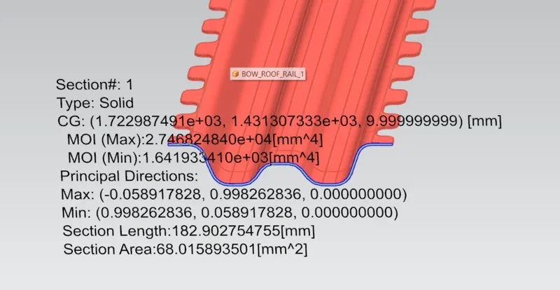
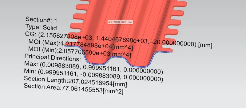
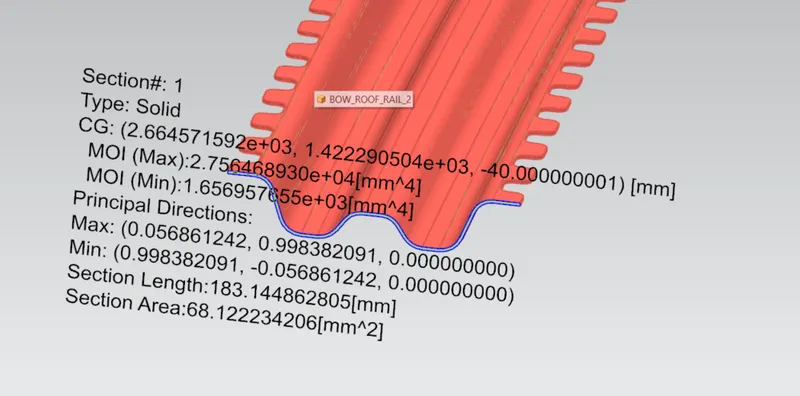
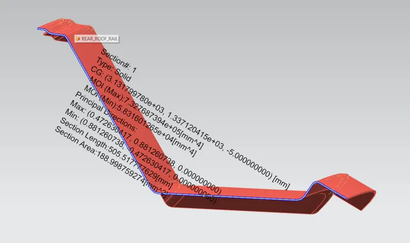
Section Inertia analysis of the Roof Rails :
- FRR
- BRR 1
- CRR
- BRR 2
- RRR
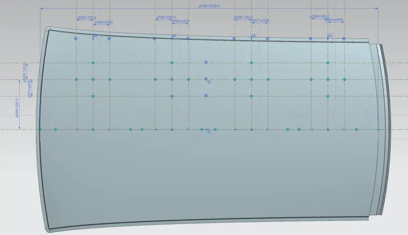
Heat Distortion Prediction Criteria
W = [1.73*(10-3)*L] + [1.85*(10-8)*(R2)/t] + (1.10*(10-3)*I] - 2.68
Where,
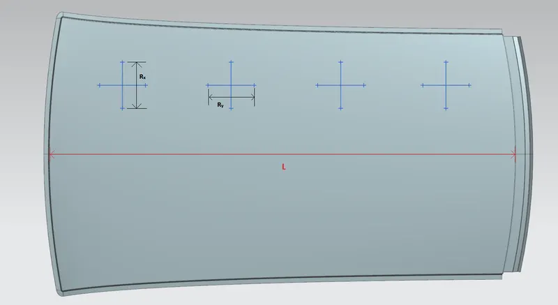
L = Roof Length in X-direction, i.e. in 0-Y dimension (mm).
R = Roof Curvature,
R = (2*(Rx+Ry) / (Rx+Ry))
Rx = Curvature in X-direction (mm).
Ry = Curvature in Y-direction (mm.
t = Roof plate thickness (mm).
I = Bow Roof Span (mm).
Judgement Condition : W < 2.7mm
|
Section |
Rx (mm) |
Ry (mm) |
R (mm) |
I (mm) |
t (mm) |
L (mm) |
W (mm) |
Result |
|
FRR - BRR 1 |
5723.48067 |
2762.70585 |
3726.59580 |
449.4897 |
0.75 |
2028.3552 |
1.666 |
PASS |
|
BRR 1 - CRR |
4900.57829 |
6485.66189 |
5582.78999 |
357.4292 |
0.75 |
2028.3552 |
1.991 |
PASS |
|
CRR - BRR 2 |
3981.48805 |
10560.70647 |
5782.80349 |
433.1414 |
0.75 |
2028.3552 |
2.130 |
PASS |
|
BRR 2 - RRR |
3287.74378 |
14538.49707 |
5362.75188 |
343.6945 |
0.75 |
2028.3552 |
1.916 |
PASS |
Snow-load Prediction Criteria
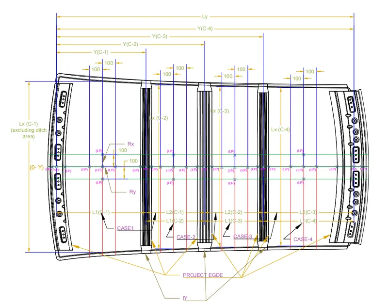
Qr = {Iy * t2} / {α*s* [(Rx+Ry)/2]2 *10-8}
Where,
α = My*Lx*10-12
My = Y*(Ly - Y)
t = Roof plate thickness (mm).
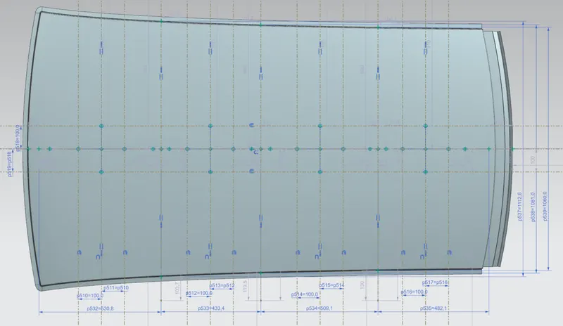
Ly = Distance between the front and rear roof rails on the vehicle along 0-Y dimension (mm).
Length of roof panel with the center point between Front/Rear roof rails as the front and rear reference point.
Lx = Distance between the left and right end of the roof on the Roof Bow (mm).
The width of the panel is exposed on the surface.
Y = Distance from Front Roof Rail to Bow Roof (mm).
s = Distance for which Roof Bow bears divided load (mm).
s = ((L1 + L2)/2)
Iy = Geometrical Moment of Inertia of Roof Bow [Y cross-section] (mm4).
Rx = Lateral direction curvature radius of roof panel [Y cross-section on Roof Bow] (mm).
Roof panel curvature radius of the length Lx in Front-view.
Ry = Longitudinal direction curvature radius of roof panel [X cross-section on Roof Bow] (mm).
Roof panel X curvature radius of the length s in Side-view.
Judgement Condition : Qr ≥ 3.1
250 ≤ s ≤ 380
|
Section |
Rx (mm) |
Ry (mm) |
Lx (mm) |
Ly (mm) |
Y (mm) |
My |
α |
Iy (mm4) |
t (mm) |
L1 (mm) |
L2 (mm) |
s (mm) |
Qr |
Result |
|
|
s |
Qr |
||||||||||||||
|
BRR 1 |
4426.66379 |
2794.56289 |
1112.6150 |
1955.4712 |
530.8488 |
756259.0915 |
0.936182309 |
1641.93341 |
0.75 |
530.8488 |
433.4438 |
482.14630 |
15.6956 |
F |
P |
|
CRR |
3780.50398 |
6406.37936 |
1080.0415 |
1955.4712 |
964.2926 |
955786.1893 |
1.114914689 |
2057.70659 |
0.75 |
433.4438 |
509.0669 |
471.25535 |
8.49152 |
F |
P |
|
BRR2 |
4273.62705 |
11054.2171 |
1060.0150 |
1955.4712 |
1473.3595 |
710323.8533 |
0.79814247 |
1656.95765 |
0.75 |
509.0669 |
482.1116 |
495.58925 |
4.01171 |
F |
P |
|
RRR |
4018.89060 |
16321.95533 |
1056.4926 |
1955.4712 |
1955.4712 |
0 |
0 |
58316.0126 |
0.75 |
482.1116 |
0 |
241.0580 |
- |
F |
- |
Draft analysis :
- FRR
- BRR 1
- CRR
- BRR 2
- RRR
- Roof
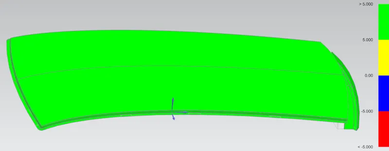
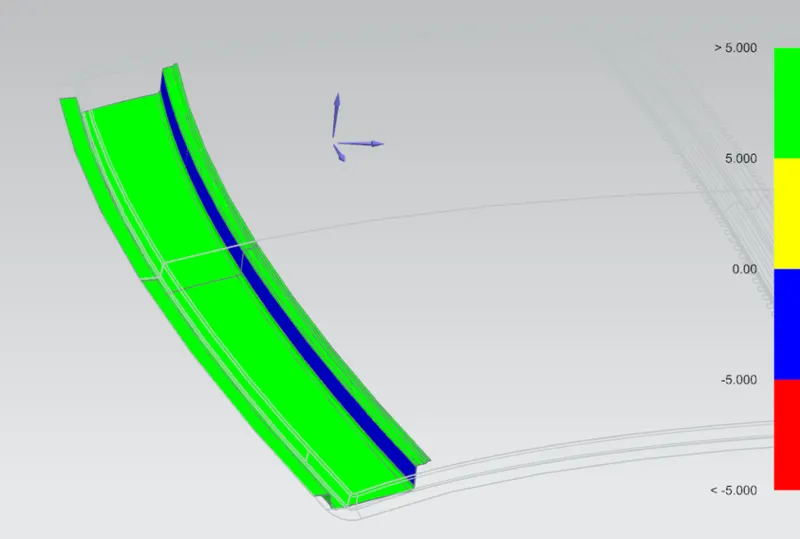
Note :- All the components pass the draft analysis, as the draft angle on all components is ≥7°.
Conclusion :
- The required roof is designed with reference to the master section.
- The roof rails, i.e, a Front Roof Rail, a Center Roof Rail, a Rear Roof Rail and two Bow Roof Rails, are designed by using the data from the master sketches provided.
- Curvature Studies on the roof is conducted and the results are tabulated.
- Draft analysis is done.