Roof Design
INTRODUCTION-
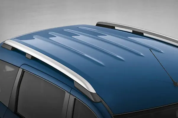
An automobile roof or car top is the portion of an automobile that sits above the passenger compartment, protecting the vehicle occupants from sun, wind, rain, and other external elements. Because the earliest automobiles were designed in an era of horse drawn carriages, early automobile roofs used similar materials and designs.
Roof system made up of polycarbonate, glass-plastic composite, and fibre-plastic composite and polyurethane composite are used in hybrid cars to save energy, and light weight construction. Revenue generated from the sales of automotive roof systems, globally is expected to increase at a moderate CAGR over the forecast period.
ROOF CRUSH TEST-
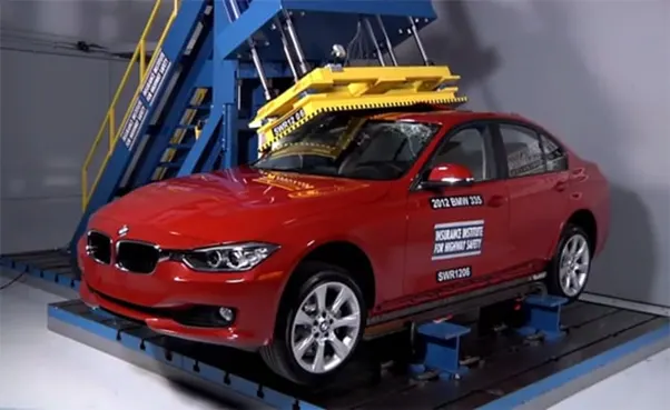
The vehicle performances for the side impact test and the roof crush test are dependent on the side structure design of a vehicle. Crash optimization can be employed to enhance the performances. A meta-model-based structural optimization technique is generally utilized in the optimization process since the technique is simple to use. However, the meta-model-based optimization is not suitable for problems with many design variables such as topology and topometry optimizations. A crash optimization methodology is proposed to consider both the side impact test and the roof crush test. The equivalent static loads method is adopted for the side impact test and the enforced displacement method is adopted for the roof crush test, and the two methods are integrated. A design formulation is defined. The survival distance from the side impact test and the roof strength for the roof crush test are used for the design constraints. Crash optimization is performed for a practical large-scale structure. For conceptual design, reinforcement of the B-pillar is determined by using topometry optimization, and size and shape optimizations are employed for a detailed design to satisfy the design constraints while the mass is reduced.
DESIGN CONSIDERATION-
- Visibility criteria
- Head room clearance
- Bow roof position
- Heat distortion and Snow load criteria
- Draft analysis
COMPONENTS OF ROOF-
- Roof outer panel-
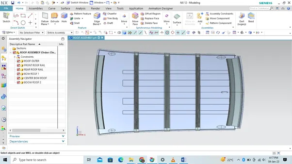
It is necessary to remove any discontinuity in the styling surface which may result in faulty surfaces. Also it helps to generate smooth surfaces while performing complex operations. Surfaces were extracted from the given styling data and untrimmed to get the original surface back.
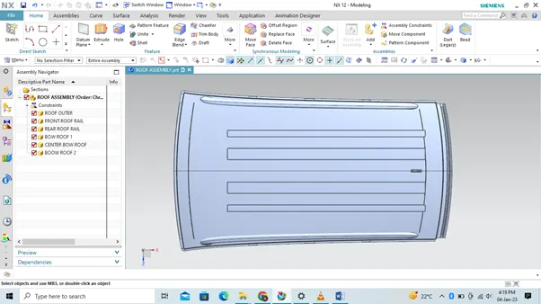
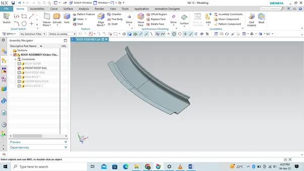
- Front rail roof- The front roof rail is located on the front of the roof where the wind shield joins with the roof. The visibility criteria and the head room clearance of the passenger are taken into consideration for the bottom flange. One end of the rail is joined using spot welding while the other end is joined with the roof using mastic sealants for increased strength.
- Bow roof 1-
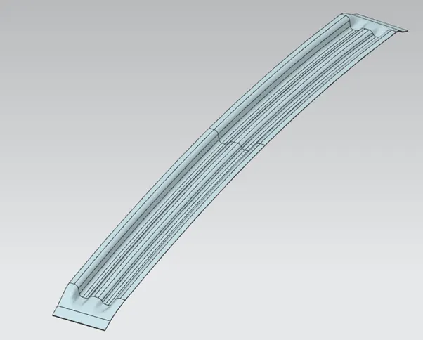
Bow roof is an additional siffening member for the roof to increase the strength and so that it can satisfy the norms. Both the ends are joined together using mastic sealants to increase strenght and also since this would not affect the styling of the roof.
- Center roof rail-
Centre Roof rail or the reinforcement centre is located at the centre of the roof . The cross section of this is more since it needs to provide more strength to the roof. Here both are ends are joined together using mastic sealants.
- Bow roof 2-
This bow roof also have the same purpose as that of the first one. This one is located between the centre bow roof and rear roof rail.
- Rear roof rail-
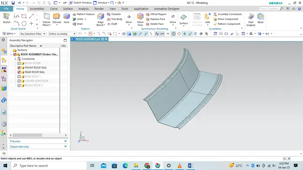
This roof rail joins with the back door and the roof. Inputs from the backdoor are taken into consideration for designing this roof rail.
Here one end is joined using spot welding while the other end is joined using mastic sealants.
- Ditch area-
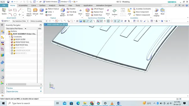
A roof ditch area extending in a generally longitudinal direction of a vehicle is fixedly coupled to a body member and form a longitudinal water management channel on a lateral side portion of a roof of the vehicle. It is a styling orient part, so it is produce inhouse only.
CALCULATION-
- HEAT DISTORTION -
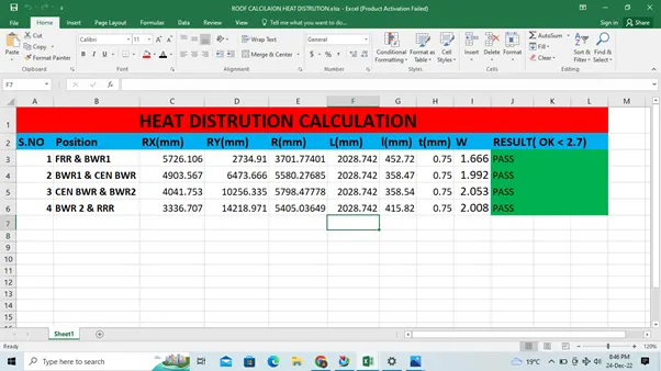
Heat distortion temperature is the temperature at which the metal softens and deforms under a specific load. This study is done to check the ability of the roof to withstand high temperature with respect to the positioning of the reinforcements which contribute to increased strength.
W = [1.73 x 10^(-3) x L] + [1.85 x 10^(-8) x (R^2)/t] + [ 1.10x10^(-3) x l] - 2.68
Judgement Condition : OK< 2.7> 3.1
Where
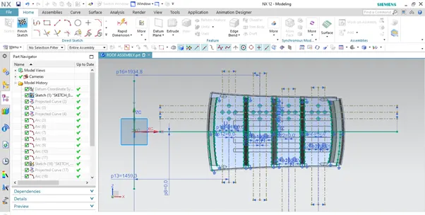
L = Roof Length in X-Direction[mm](Roof dimension in 0-Y)
R = Roof curvature
R = 2(Rx*Ry)/(Rx+Ry)
Rx = X curvature
Ry = Y curvature
t = Roof plate thickness [mm]
l = Bow Roof Span [mm]
L = Roof Length in X-Direction[mm](Roof dimension in 0-Y) and l = Bow Roof Span [mm]-
- SNOW LOAD-
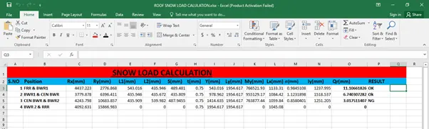
Snow load criteria study is used to check the durability of the roof to withstand the snow fall on the roof and reflex it is original shape without any permanent deformation after load being removed.
Qr = [Iy x t2] / [α x s x [(Rx + Ry)/2]2 x 10-8]
Where,
α = My x Lx2 x 10-12 , My = Y(Ly-Y)
t = Roof plate thickness [mm]
Ly = Distance between the front and rear roof Rails on the Vehicle along with 0Y[mm]
Length of Roof panel with the center point between Roof rail Front /Rear as the front and rear reference point.
Lx = Distance between the Left and Right end of the roof on the Roof BOW [mm]
The width of the roof panel is exposed on the surface.
Y = Distance front Front Roof Rail to Roof BOW[mm]
s = Distance for which Roof BOW bears divided load [mm]
s = L1/2 + L2/2
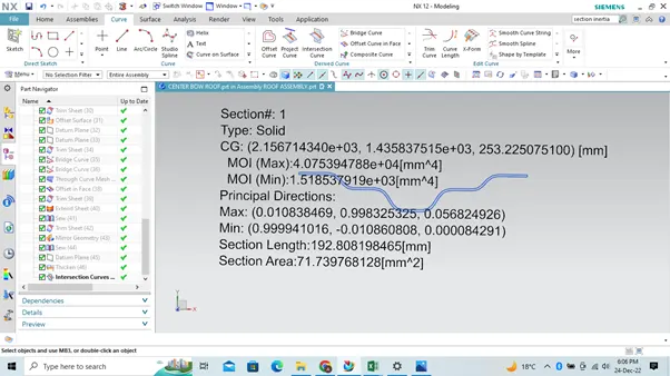
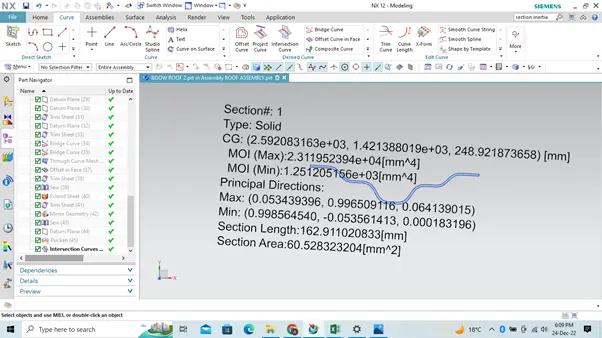
Iy = Geometrical moment of inertia of Roof BOW (Y cross-section )[mm4]
Rx = Lateral direction curvature radius of roof panel Y cross-section on Roof BOW [mm]
Roof panel curvature Radius of the Length Lx in Front view
Ry = Longitudinal Direction curvature radius of the Roof panel X cross-section on Roof BOW [mm]
Roof panel X curvature radius of length s in Side view
Judgment condition
Qr ≥ 3.1
250 ≤ s ≤ 380
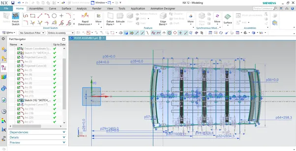
Moment of inertia of Bow Roof 1-
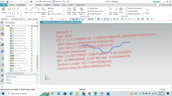
Moment of inertia of center roof-
Moment of inertia Bow roof 2-
Note:- Crate the emboss for roof outer panel increase the strength.
DRAFT ANALYSIS-
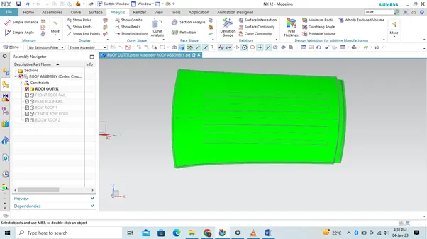
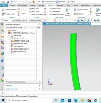
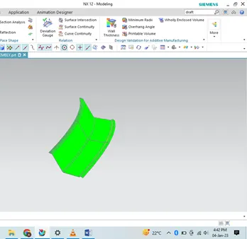
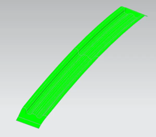
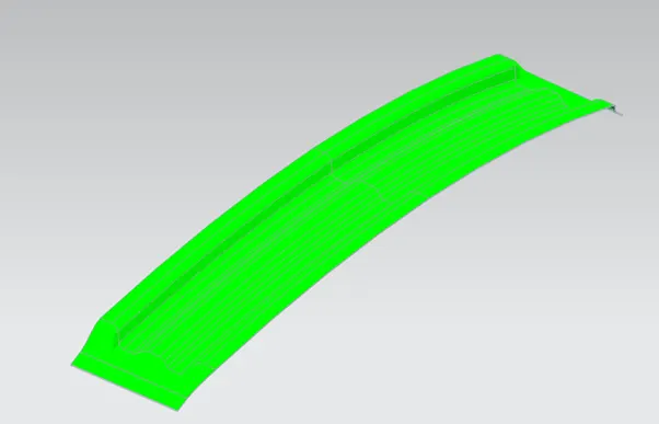
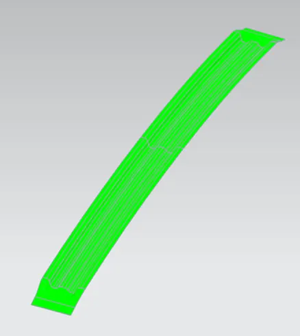
The Bevel Analysis command lets you see if the part you've created will be easily removed. This type of analysis is performed based on color ranges identifying zones on the analyzed element where the deviation from the dip direction at any point corresponds to the specified values.
A minimum bevel angle of 7 degrees is considered for the analysis. The green color indicates a positive component bevel angle greater than 7 degrees.
Draft analysis of roof outer panel-
Draft analysis of front roof rail-
Draft analysis of rear roof rail-
Draft analysis of Bow roof 1-
Draft analysis Center roof rail-
Draft analysis of Bow roof 2-
CONCLUSION-
We have successfully managed to design a roof with all roof rails for better support and strength. We designed it to meet standards and regulations by calculating thermal deformation criteria and snow load criteria. In doing so, we also understood what the methodology of designing a car roof is and what we take into account when designing.