Roof Design
ROOF DESIGN
OBJECTIVE:
- For the Given Roof styling, develop the essential flanges
- Creation of Roof ditch area with tool opening angle of 3 degree.
- Provide appropriate dimensions and validate for Draft analysis.
- Section modulus study on 0-Y section for the Master sections created for Front roof rail, Rear roof rail, and Bow Roof Rails.
- Perform curvature study on the roof and calculations to determine the position of the Bow-roof.
ROOF DESIGN:
A roof of a car consists a outer skin panel which is designed with aesthetics and aerodynamics in mind and the support structure of the panel. In case of passenger cars the roof is designed to be flexible enough to regain its original shape after smaller loads due to snow of light impacts are applied to it. At the same time the roof needs to withstand all the impact forces and self weight in a roll over incident. Hence the support structure is a vital part of the roof design. Usually it consists of a Front roof rail, a rear roof rail, roof reinforcement, and 1 or more bow rails.
The front and rear roof rails are used to join the roof with the rest of the BIW of the car along with front windshield, dampening components, sealants etc. Roof reinforcement panel is provided where the roof is flatter usually in the middle along the length of the car again to provide strength to the roof. Bow roof rails are provided as and when necessary, and are attached to the roof panel using mastic sealants. The longer the roof, more the number of bow rails. The dimensions of the support structure like the depth and length which will affect the front and rear visibility, interior design and material required, headroom and overall space it will occupy is governed by ergonomics and region specific regulations where the car is to be sold.
Roof Assembly 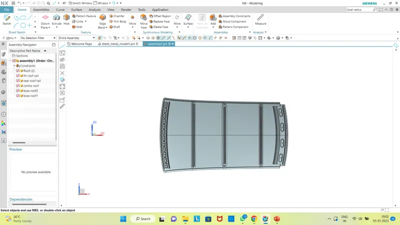
DESIGN CONSIDERATION:
- Visibility criteria
- Head clearance
- Curvature study
- Hear distortion and snow load criteria
- Draft analysis.
DESIGN OF FRONT ROOF:
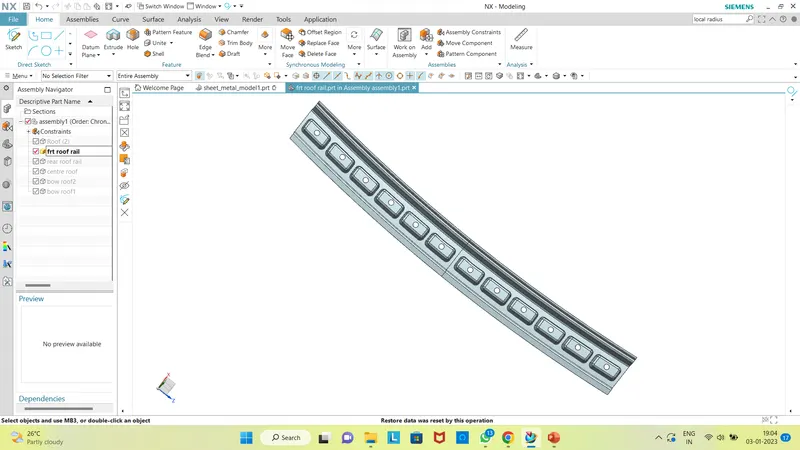
The front rail underpins the rooftop external shell at the front end. It is mounted with support rooftop rail fortification on the two closures. The rails are furnished with embosses to improve the strength over the length and the rail is associated with the external board utilizing mastic sealants on one side and the other joinery is spot welded. It is the support that is joined with the Wind Shield Glass, Body Side Outer, and inner panels. It is usually made from Body Side Outer scrap and therefore the thickness of the rail is 0.75 mm. The bottommost flange is decided after taking into consideration the visibility criteria and the Headroom Clearance of the passenger. Spot Welds are applied at the Windshield end of the rail and the other end is joined with the roof using Mastic Sealants which also contributes to increased strength.
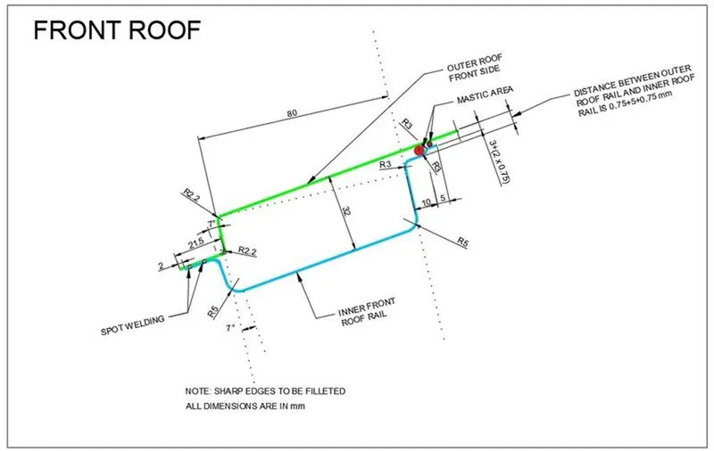
FRONT ROOF RAIL
DESIGN OF REAR ROOF:
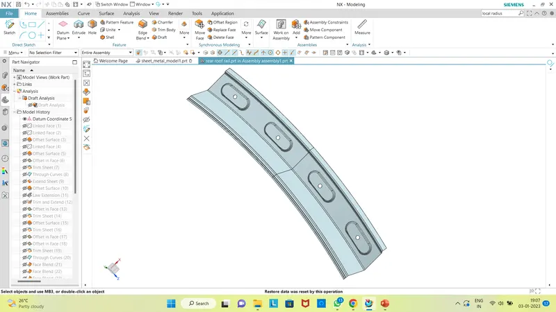
It is the support that is joined to the Back Door and the Body Side Outer and inner panels. Similar to the Front Roof Rail design, we have to take into consideration the rear Headroom Clearance while designing the Rear Roof Rail. Inputs are taken from the rear master section. It is also usually made from Body Side Outer scrap and therefore the thickness of the rail is 0.75 mm. Spot Welds are applied at the Back door end of the rail and the other end is joined with the roof using Mastic Sealant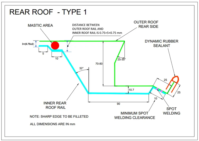
REAR ROOF RAIL
DESIGN OF BOW ROOF :
The Bow roofs are given to improve the torsional stiffness and load-bearing capacity of the roof structure. The number of bow roofs provided will depend upon the overall dimensions of the roof. The longer the roof more the bow roofs are integrated into the BIW frame They are attached to the outer panel using mastic sealants. The positioning of bow roofs is done based on a curvature study. The heat distortion criteria and snow load criteria are checked to analyze the position of the bows in various conditions. The thickness of the Bow Roof is 0.75 mm and also mastic area has been created. Two Bow roofs are required for this project so we will have to make 2 bow roofs with the same master section properties.
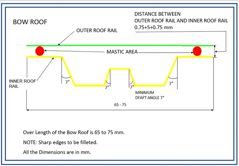
BOW ROOF RAIL
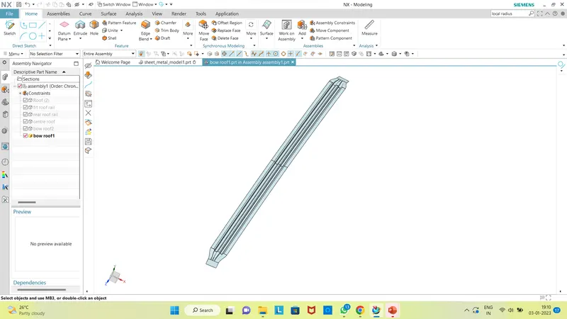
THE NUMBER OF BOW ROOF DEPENDS UPON THE CROSS SECTION OF THE ROOF SURFACE
DESIGN OF CENTER ROOF:
Centre roof rail is provided to effectively support the flat area of the roof as it is more susceptible to failure under the action of the load. Usually, the center reinforcement roof rail will be placed at the center of the roof connecting the B pillar support structure which results in added support in the roll-over test. The thickness of the center bow roof is 0.75 mm thickness.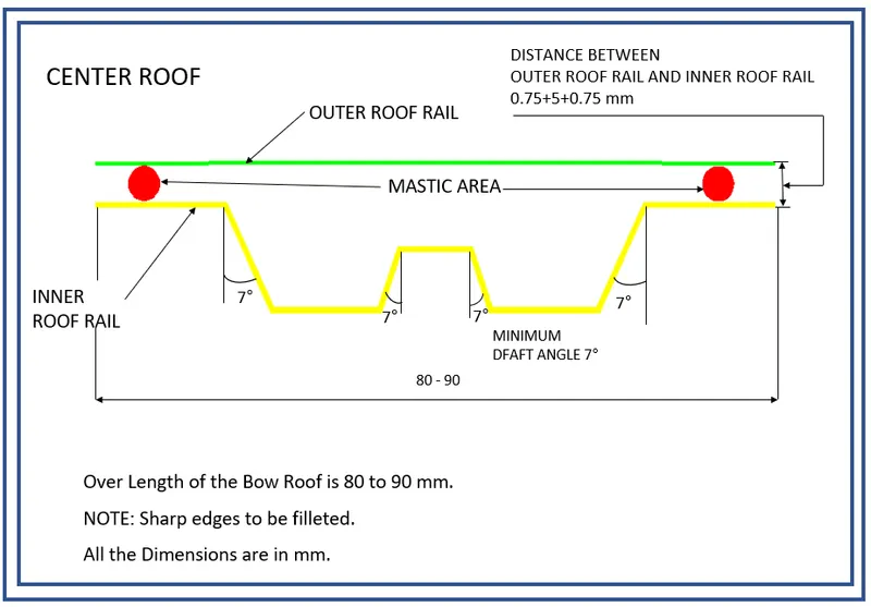
CENTRE ROOF RAIL
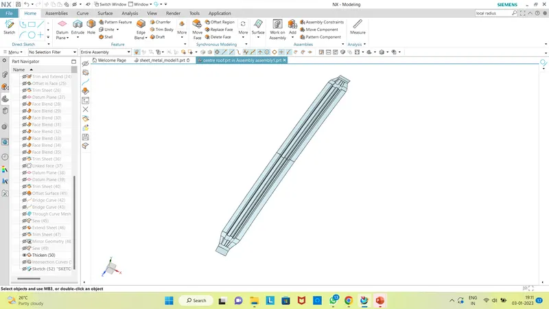
THE CENTRE ROOF RAIL IS SIMILAR TO BOW ROOF BUT DIFFERS IN WIDTH
CALCULATIONS
HEAT DISTORTION;
This study is used to find out and predict the heat distortion temperature at where the material starts to soften when exposed to a fixed load. So in order to avoid bending or damage of the roof based on this calculation we will decide the position on the roof bows on the roof.
W = [1.73 x 10^(-3) x L] + [1.85 x 10^(-8) x (R^2)/t] + [ 1.10x10^(-3) x l] - 2.68
Where,
L = Roof Length in X-Direction[mm](Roof dimension in 0-Y)
R = Roof curvature
R = 2(Rx*Ry)/(Rx+Ry)
Rx = X curvature
Ry = Y curvature
t = Roof plate thickness [mm]
l = Bow Roof Span [mm]
Judgment Condition
OK< 2.7
RX AND RY CALCULATIONS:
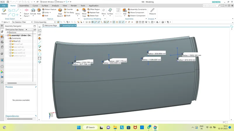
L VALUE DERIVATION
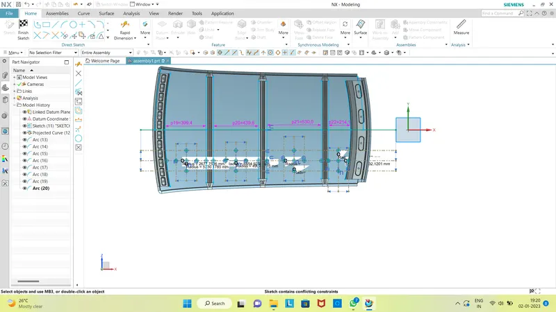
RESULT:

SNOW LOAD CRITERIA :
Snow load criteria is useful to justify the bow roof rail position in snow fall regions. Due to snow fall snow will get collected on the top roof which will tend to bend the roof. Bow roof will be at such position which will provide more strength to roof against bending.
Qr = [Iy x t2] / [α x s x [(Rx + Ry)/2]2 x 10-8]
Note: The Qr value given over here is correct. There was a typo error in the formula given in the video.
Where
α = My x Lx2 x 10-12 , My = Y(Ly-Y)
Judgement condition = Qr ≥ 3.1
250 ≤ s ≤ 380
t = Roof plate thickness [mm]
Ly = Distance between the front and rear roof Rails on the Vehicle along with 0Y[mm]
Length of Roof panel with the center point between Roof rail Front /Rear as the reference point of the front and the rear.
Lx = Distance between the Left and Right end of the roof on the Roof BOW [mm]
Width of the roof panel exposed on the surface.
Y = Distance front Front Roof Rail to Roof BOW[mm]
s = Distance for which Roof BOW bears divided load [mm]
s = L1/2 + L2/2
Iy = Geometrical moment of inertia of Roof BOW (Y cross-section )[mm4]
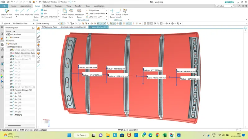
Rx = Lateral direction curvature radius of roof panel Y cross-section on Roof BOW [mm]
Roof panel curvature Radius of the Length Lx in Front view
Ry = Longitudinal Direction curvature radius of the Roof panel X cross-section on Roof BOW [mm]
RX AND RY CALCULATIONS :
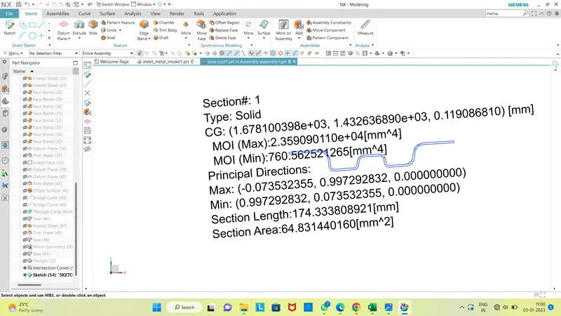
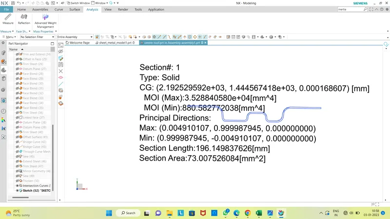
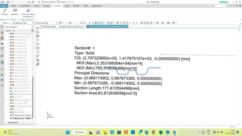
SECTION MODULUS CALCULATION :
BOW ROOF 1 SECTION INERTIA :
CENTRE ROOF SECTION INERTIA :
BOW ROOF 2 SECTION INERTIA :
RESULTS :

DRAFT ANALYSIS :
It is done to check if the features designed clear the minimum draft 5 degree for manufacturabililty. This type of analysis is performed based on color ranges identifying zones on the analyzed element where the deviation from the draft direction at any point, corresponds to specified values.
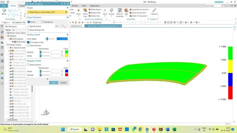
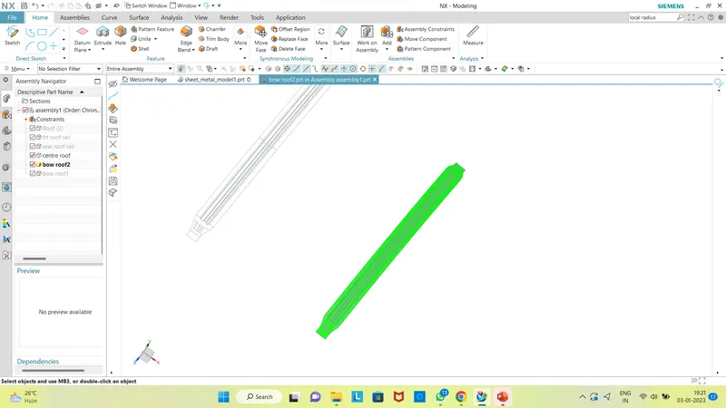
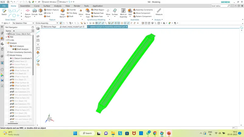
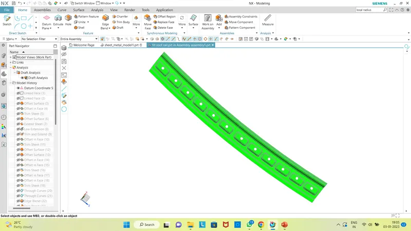
It is seen that the features designed clears the minimum draft angle which denoted in 'green'
Conclusion:
- Essential roof components such as bow and center rails required with flanges and reinforcements are designed.
- Curvature study on roof was analysied with heat distortion and snow load standards
- Draft analysis was done to check toolablilty.