Roof Design
ROOF DESIGN
AIM: To design a roof with all the components like front roof rail, rear roof rail, and bow roofs by following the given master sections and the high-quality surface, considering all the design requirements as per the OEM standards.
ROOF :
An automobile roof or car top is the portion of an automobile that sits above the passenger compartment, protecting the vehicle occupants from sun, wind, rain, and other external elements. The roof is not a single panel as seen from the exterior it consists of front roof rail, bow roofs, center roof rail, and rear roof rail with different thicknesses which act as a reinforcement for the top.
OBJECTIVE:
1.To design a roof of the car with all the reinforcement from the given styling surface.
2.To perform the curvature study on the roof by considering Heat Distortion and Snow load criteria.
3.To calculate the moment of inertia for the reinforcements.
4.To Perform the draft analysis for analyzing the components' manufacturing feasibility.
TYPICAL SECTIONS:
1.Front Roof Rail.
2.Rear Roof Rails.
3.Center Roof with a reinforcement.
4.Bow Roof Rails.
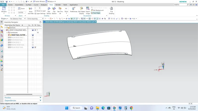
GIVEN SKIN:
Using this skin we are creating the Front,Rear,Bow,and Center roof are created.
FRONT ROOF RAIL:
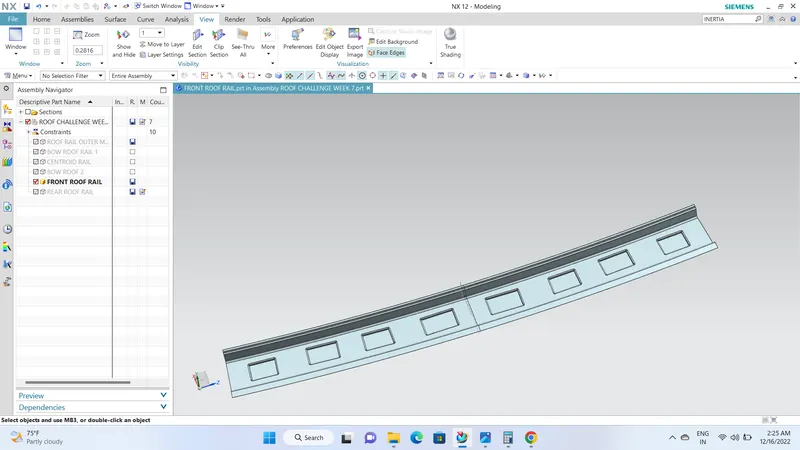
Front Roof Rail is a reinforcement that features to back of the bracket lamp and the room lamp and it also serves the purpose of attaching the windshield. The development of the FRR is based on the given master section and also references from the given styling and the front ditch area are taken into consideration. Embosses and darts are incorporated for strengthening the part.
GIVEN MASTER SECTION:
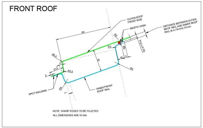
By following the given Master section Front Roof Rail has been designed
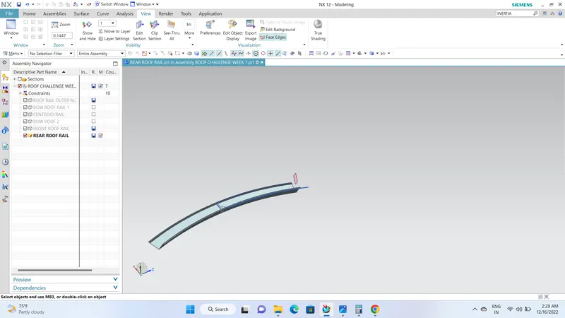
REAL REAR ROOF:
It is a reinforcement provided to the rear portion of the roof and it also features the tailgate mountings. The development of Rear roof is dependent upon the rear headroom clearance and rear visibility criteria.
GIVEN MASTER SECTION:
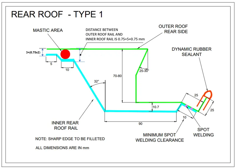
By following the given Master section Rear Roof Rail has been designed.
BOW ROOF RAILS:
These are the reinforcements provided on the most flatter regions of the roof which are more susceptible to failure. The number of bow roofs depends upon the length of the roof i.e, longer roofs have more bow roofs like vans. For the development of the bow roofs, the styling surface and side ditch area are taken as references.
GIVEN MASTER:
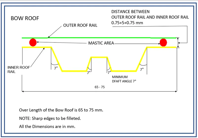
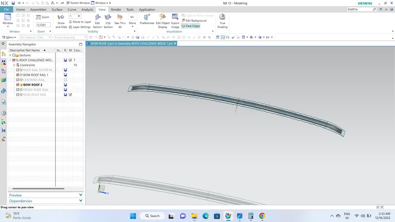
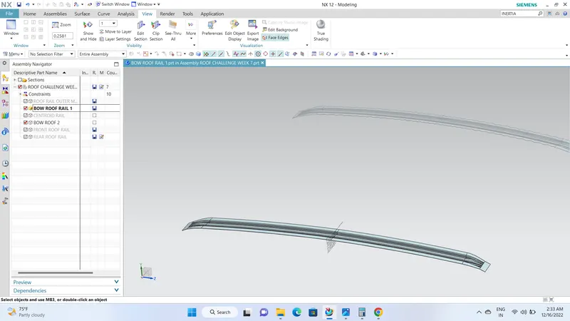
By following the given Master section Bow 1 and 2 Roof Rail has been designed.
BOW 2:
BOW 1:
CENTER ROOF:
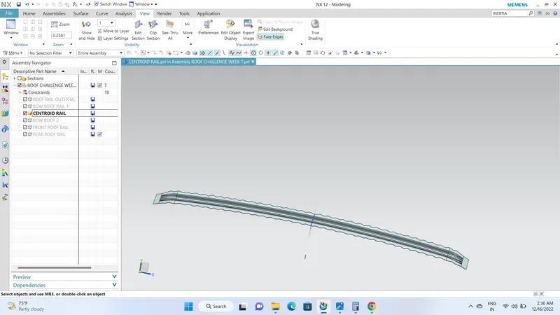
These roof rails are positioned mostly on the center portion of the roof or at the B Pillar of the vehicle i.e, the most flatter region of the car which is susceptible to failure under the action of load.
GIVEN MASTER SECTION:
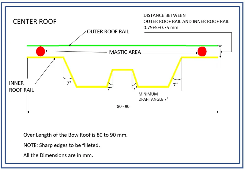
By following the given Master section Center Roof Rail has been designed.
DITCH AREA:
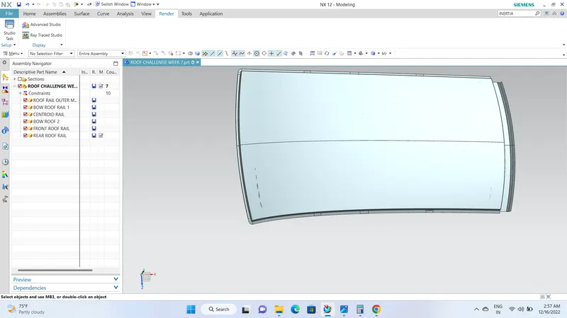
The ditch area is the extended portion of the main roof which is concealed by the other BIW components followed by the other aesthetic surface. It also serves the joining purpose for the reinforcement which is joined using the spot welding. Visibility, Clearance for windshield and back door mountings are some of the factors needed to be considered while designing the ditch area.
FINAL ASSEMBLY:
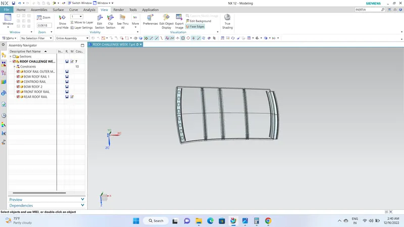
The Flanges of the front and rear roof rail and flanges of the bow roofs and center roof rail are joined using the spot welding, whereas mastic sealants are provided along the roof rails to improve the strength and also to avoid bad marks on the aesthetic surfaces.
SECTION MODULES:
- Section modulus is a direct measure of strength of any sectional area of an object about an reference axis(neutral axis).
- Strength is nothing but, capable of supporting greater loads, so higher the strength it has a high capable of supporting greater loads.
- This strength can measured directly from Section modulus formula, and defined by below formula.
S = I/y
Where,
S = Section Modulus
I = Moment of Inertia
y = distance between the neutral axis and the extreme end of the object
FRONT ROOF:
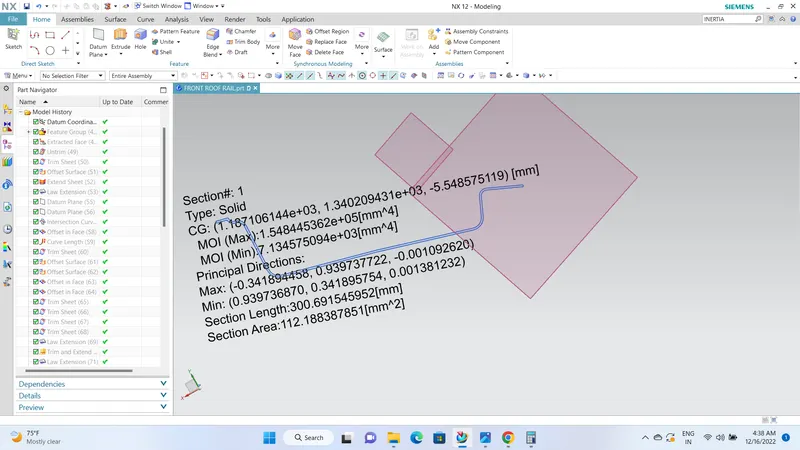
I=7.134e^3mm^4
Y=A/2
Y=121.40/2=60.2mm
S=I/Y
S=7.134e^3/60.2= 2.3400 mm3
REAR ROOF:
I=4.02335e^3mm^4
y=96.62mm
s= 0.83568472mm^3
CENTER ROOF:
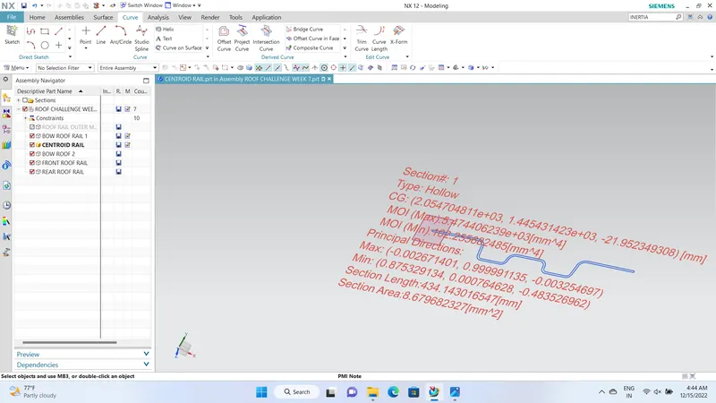
I=102.255mm4
Y=36.53mm
S=2.7992mm3
BOW ROOF 1:
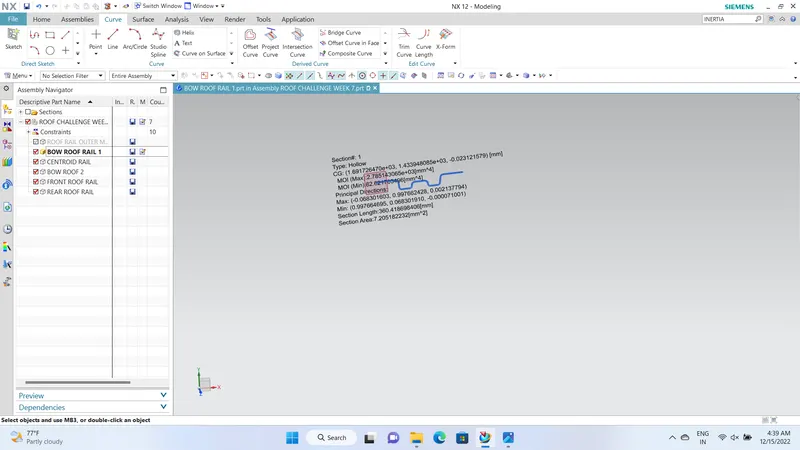
I=82.6217mm4
Y=35.95 mm
S=2.2982mm3
BOW ROOF 2:
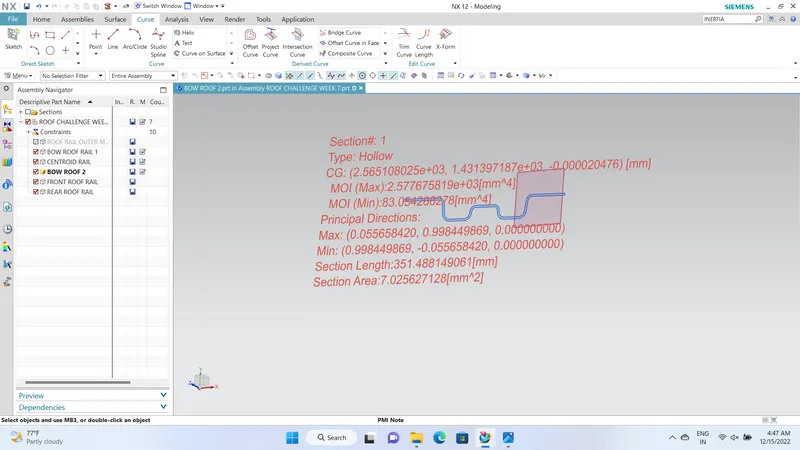
I=83.0542mm4
Y=34.80mm
S=2.3866mm3
HEAT DISTORTION CRITERIA:
Heat distortion temperature is the temperature at which the metal softens and deforms under a specific load. This study is done to check the ability of the roof to withstand high temperatures concerning the positioning of the reinforcements which contribute to increased strength.
Procedure:
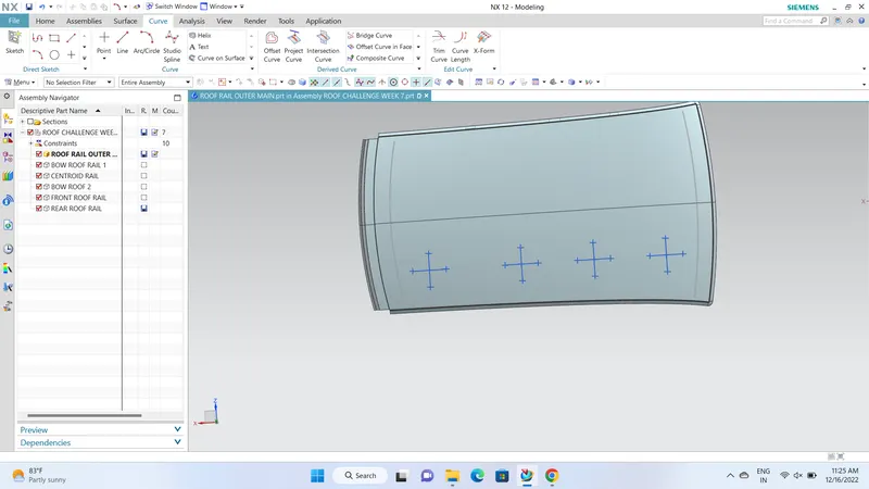
Create a center line at the 0-Y region of the roof and then offset the same to -3Y.
Create a symmetric line from the -3Y region at a distance of 100mm.
Draw a vertical line at the midpoint of the line drawn from the center points of the FRR and BR 1 and followed the same till the rear roof rail.
Offset the vertical line to a distance of 100mm on each side.
Create intersection points and project them on the roof.
FORMULAS HEAT DISTORION
From these projected points, make a 3-point arc and the Rx and Ry values.
W = [1.73 x 10^(-3) x L] + [1.85 x 10^(-8) x (R^2)/t] + [ 1.10x10^(-3) x l] - 2.68
Where,
L = Roof Length in X-Direction[mm](Roof dimension in 0-Y)
R = Roof curvature
R = 2(Rx*Ry)/(Rx+Ry)
Rx = X curvature
Ry = Y curvature
t = Roof plate thickness [mm]
l = Bow Roof Span [mm]
Judgment Condition
OK< 2.7
R = 2(Rx*Ry)/(Rx+Ry)
R=2(3172.56*5737.570/(3172.56+5737.57)
R=4085.86mm
W = [1.73 x 10^(-3) x L] + [1.85 x 10^(-8) x (R^2)/t] + [ 1.10x10^(-3) x l] - 2.68
W = [1.73 x 10^(-3) x 2033] + [1.85 x 10^(-8) x (4085^2)/0.75] + [ 1.10x10^(-3) x 423.6953] - 2.68
W=1.3131
Judgment Condition
OK< 2.7
1.3131<2.7 so the judgement condition is ok
simillarlly
| SNO | BOWS | RX | RY | R | I | L | t | W | REMARKS |
| 1 | FR-BOW1 | 3172.56 | 5737.57 | 4085.86 | 423.6953 | 2033 | 0.75 | 1.3131 | OK |
| 2 | BOW1-CR | 5946.50 | 8069.66 | 6847.27 | 287.5452 | 2033 | 0.75 | 2.308 | OK |
| 3 | CR-BOW2 | 9643.86 | 6045.88 | 7432.32 | 442.4298 | 2033 | 075 | 2.68 | NOT OK |
| 4 | BOW2-RR | 14460.45 | 3298.60 | 5371.82 | 476.3019 | 2033 | 075 | 2.0725 | OK |
A snow load study is done to check the ability of the roof to withstand snowfall and bounce back to its original position without undergoing permanent deformation upon the removal of the load.
Procedure:
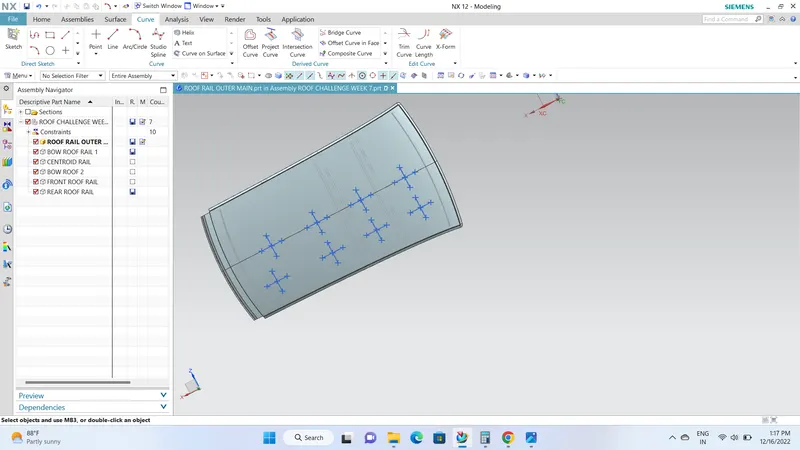
- Create a center line at the 0-Y region of the roof and then offset the same to 100mm on each side.
- Draw a vertical line at the midpoint of the line drawn from the center points of the FRR and BR 1 and followed the same till the rear roof rail.
- Offset the vertical line to a distance of 100mm on each side.
- Create intersection points and project them on the roof.
- From these projected points, make a 3-point arc and the Rx and Ry values.
- Project the extreme edges of the styling surface fro measuring the width at the respected sections.
Snow Load Prediction Formula
Qr = [Iy x t2] / [α x s x [(Rx + Ry)/2]2 x 10-8]
Note: The Qr value given over here is correct. There was a typo error in the formula given in the video.
Where,
α = My x Lx2 x 10-12 , My = Y(Ly-Y)
t = Roof plate thickness [mm]
Ly = Distance between the front and rear roof Rails on the Vehicle along with 0Y[mm]
Length of Roof panel with the center point between Roof rail Front /Rear as the front and rear reference point.
Lx = Distance between the Left and Right end of the roof on the Roof BOW [mm]
The width of the roof panel is exposed on the surface.
Y = Distance front Front Roof Rail to Roof BOW[mm]
s = Distance for which Roof BOW bears divided load [mm]
s = L1/2 + L2/2
Iy = Geometrical moment of inertia of Roof BOW (Y cross-section )[mm4]
Rx = Lateral direction curvature radius of roof panel Y cross-section on Roof BOW [mm]
Roof panel curvature Radius of the Length Lx in Front view
Ry = Longitudinal Direction curvature radius of the Roof panel X cross-section on Roof BOW [mm]
Roof panel X curvature radius of length s in Side view
Judgment condition
Qr ≥ 3.1
250 ≤ s ≤ 380
| SNO | BOWS | RX | RY | LY | LX | Y | lY | S | Alpha | t | Qr | REMARKS |
| 1 | FR-BOW1 | 12083 | 6138.34 | 2033 | 1045.15 | 511.12 | 7.134e^3 | 453.435 | 0.849510 | 0.75 | 0.132 | OK |
| 2 | BOW1-CR | 39126 | 4172.67 | 2033 | 1044.77 | 395.71 | 82.621 | 454.665 | 0.70720 | 0.75 | 0.310 | OK |
| 3 | CR1-BOW2 | 5849.61 | 2930 | 2033 | 1044.13 | 513.66 | 102.255 | 554.895 | 0.85082 | 0.75 | 0.632 | OK |
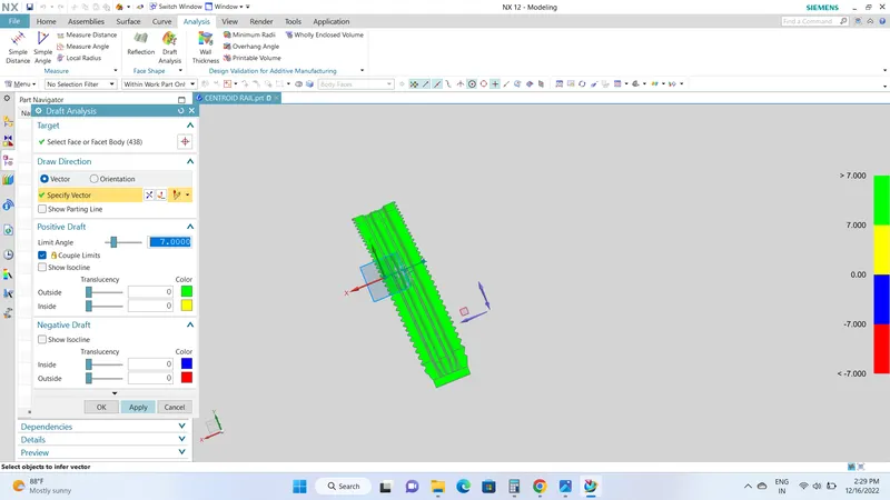
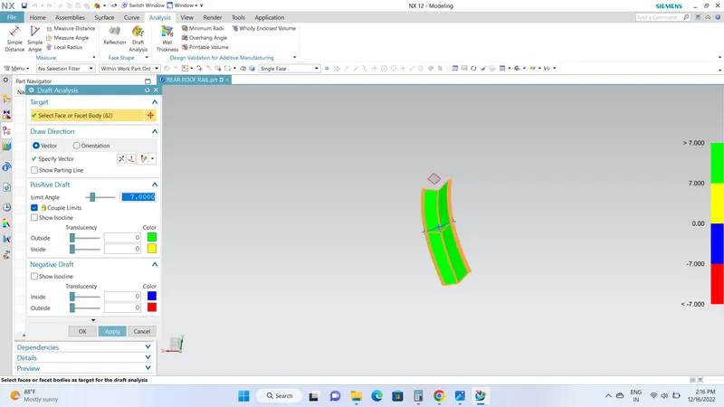
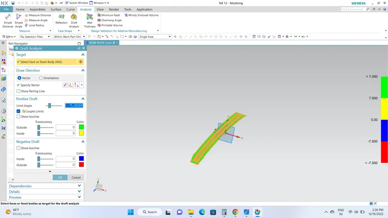
Draft Analysis :-Draft Analysis is carried out to check the manufacturing feasibility of the roof and all the reinforcements rails. All the components should be designed by considering at least the minimum draft value of 7 Deg
Front Roof Rail:
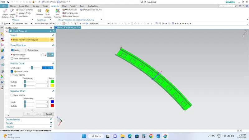
All the faces of Front Roof Rail have successfully cleared the draft analysis with a minimum draft angle of 7 degrees.
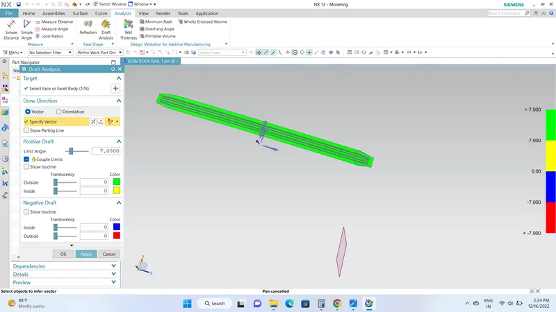
Bow Roof 1
All the faces of Bow Roof have successfully cleared the draft analysis with the minimum draft angle of 7 degrees
Centre Roof Rail
All the faces of Centre Roof Rail have successfully cleared the draft analysis with a minimum draft angle of 7 degrees.
Rear Roof RaiL
All the faces of Bow Roof Rail have successfully cleared the draft analysis with a minimum draft angle of 7 degrees.
Bow Roof 2
All the faces of Bow Roof Rail have successfully cleared the draft analysis with a minimum draft angle of 7 degrees.
CONCLUSION:
The roof has been successfully designed considering all the design Rules, Master sections, Manufacturing feasibility, Draft analysis, Heat distortion criteria, and snowload analysis.