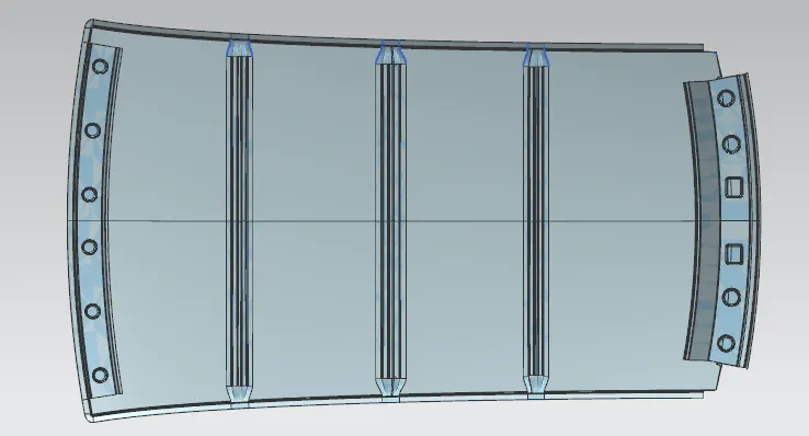
Roof Design
Roof Design
Introduction
Roof Of a vehicle:
- Roof is the top most part of a vehicle, which provides shielding to the passengers. Actually a roof of a vehicle determines a lot. They are designed considering geographical (extremely cold or hot), environmental (in which the vehicle is used) conditions of the area in which vehicle is used.
- It is made up of sheet metal. Rests on the bow roofs.
- Reinforcements are provided to strengthen the roof top.
- Front Rail, Rear Roof Rail, Center Roof Rail, and Bow Roofs are basic reinforcements of a roof.
Generally they are produced in-house.
Front Roof Rail – Joins wind shield glass, body side outer, front roof rail , inner panels.
Reinforcement and additional feature, bracket map lamp and room lamp are mounted on front roof rail.
Front roof rail is designed on the basis of Visibility Criterion and Passenger’s Head Zone Criterion.
Rear Roof Rail- It connects back door body and side outer parts.
Rear head room criterion and rear visibility are Main criterion deciding Rear Roof Rail
Design Of Roof from Input Surface
Roof is designed according to input styling surface and master sections for following,
Front Roof Rail
They are created with reference to master section.
In order to provide more strength to front and rear rails, embosses are created with cut outs.
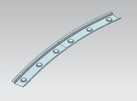
Fig.1.1 Front Roof Rail
It will provided Embosses additional strength and also reduce weight too.
In order to provide more strength to front and rear rails, embosses are created with cut outs.
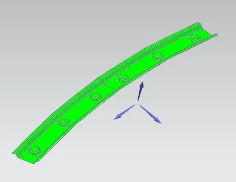
Fig.1.2 Draft analysis of Front Roof Rail
It is showing green.
It is achieved 7 degree.
Front Roof Rail- Part is clearing draft analysis, along a wall.
Bow roofs I
Here Positions of bow roofs are decided on flat surface of roof.
As height of bow roofs master sections is not provided, it is decided considering Head Clearance Criterion.
It is considerd as 18 mm.
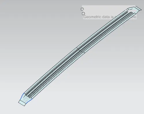
Fig.2.1 Bow Roof
Here Positions of bow roofs are decided on flat surface of roof.
As height of bow roofs master sections is not provided, it is decided considering Head Clearance Criterion.
It is considerd as 18 mm.
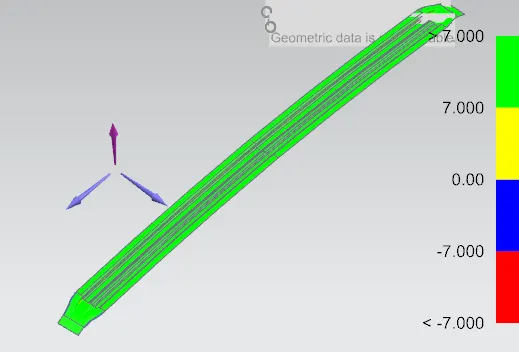
Fig.2.2 Draft analysis of Bow Roof
It is showing green.
It is achieved 7 degree.
Bow roofs II
Fig.3.1 Bow Roof II
Fig.3.2 Draft analysis of Bow Roof II
Center Roof Rail
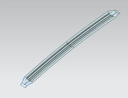
Fig.4.1 center Roof Rail
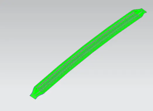
Fig.4.2 Draft analysis of center Roof Rail
Rear Roof
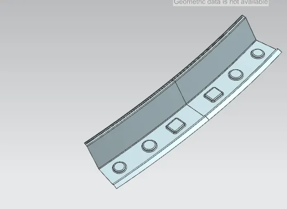
Fig.5.1 Rear Roof
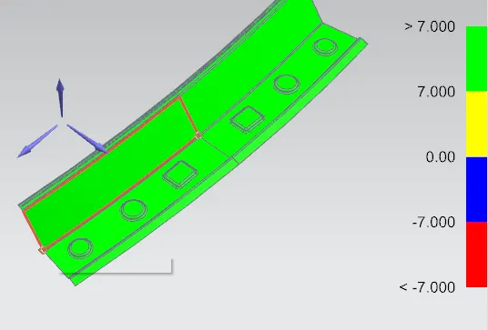
Fig.5.2 Draft analysis of Rear Roof
Outer Roof
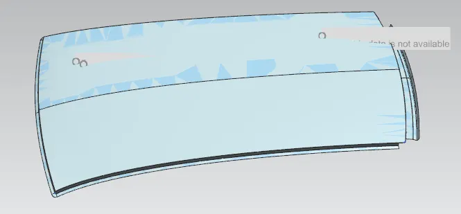
Fig.6.1 outer Roof
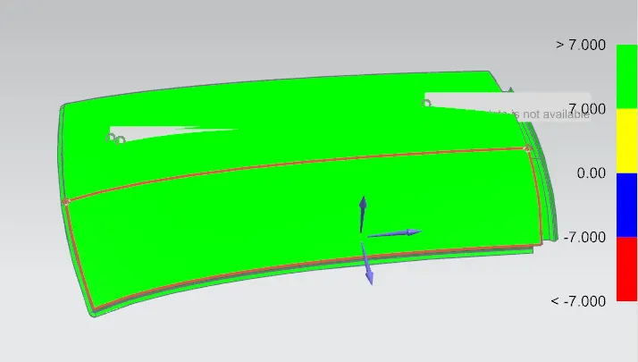
Fig.6.2 Draft analysis of outer Roof
Ditch Area Creation-
This is an extension to both the Bow Roofs and center roof rail.
Purpose- to provide sufficient space for spot welding with roof.
Draft Analysis- Is performed for all the parts created. This analysis is performed for the manufacturability of the part.
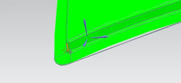
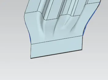
Observation-
For all three parts. there is an area with 0 to 7 degree. its inner surfce of blend in all three parts.
Clearing draft analysis.
Curvature study on the roof based on the Bow roof prediction calculation as well as the manufacturing techniques
Design is cheked for two criterion-Snow Load Prediction and Bow Roof Prdiction-
Bow Roof Prdiction- This calculation provide a guidline to decide position and number of bow roofs in a vehicle.
It W is < 2.7, deign is accepted with postions of bow roofs.
in case , if required, number of bow roofs can be adde to increase the strength.
Ideally, 2 bow roofs, and 1 center roof rail is sufficient, but depending upon curvayure, it may be increased.
bow roof adds strength to the roof.
= [1.73 x 10^(-3) x L] + [1.85 x 10^(-8) x (R^2)/t] + [ 1.10x10^(-3) x l] - 2.68
Where,
L = Roof Length in X-Direction[mm](Roof dimension in 0-Y)
R = Roof curvature
R = 2(Rx*Ry)/(Rx+Ry)
Rx = X curvature
Ry = Y curvature
t = Roof plate thickness [mm]
l = Bow Roof Span [mm]
| Column1 | Roof length | Thickness | Column2 | Column3 | Column4 | Curvature radius | Span | W=A+B+C-2.68 | Column5 | Column6 | Column7 | Column8 |
| Section | L | t | Rx | Ry | 2(Rx*Ry) | R | l | A=[1.73 x 10^(-3) x L] | B=[1.85 x 10^(-8) x (R^2)/t] | C=[ 1.10x10^(-3) x l] | W=(A+B+C)-2.68 | Remarks |
| I | 2024.5 | 0.75 | 5677.7 | 2439.5 | 27701498.3 | 3412.69 | 461.5 | 3.50 | 0.29 | 0.508 | 1.62 | True |
| II | 2024.5 | 0.75 | 5022 | 6004.5 | 60309198 | 5469.48 | 468.4 | 3.50 | 0.74 | 0.515 | 2.08 | True |
| III | 2024.5 | 0.75 | 4102.15 | 9956.6 | 81686933.38 | 5810.40 | 448.7 | 3.50 | 0.83 | 0.494 | 2.15 | True |
| IV | 2024.5 | 0.75 | 3344.9 | 14165.8 | 94766368.84 | 5411.91 | 587.8 | 3.50 | 0.72 | 0.647 | 2.19 | True |
Snow Load Prediction- Performed for vehicles in cold regions.
Roof shold be strong enough to sustaian the load of snow collected over it.
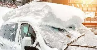
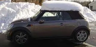
Qr value from the claculations is cheked. if it is gretaer than or equal to 3.1, deign is acceptable. or else it needed to change.
Qr = [Iy x t2] / [α x s x [(Rx + Ry)/2]2 x 10-8]
Note: The Qr value given over here is correct. There was a typo error in the formula given in the video.
Where,
α = My x Lx2 x 10-12 , My = Y(Ly-Y)
t = Roof plate thickness [mm]
Ly = Distance between the front and rear roof Rails on the Vehicle along with 0Y[mm]
Length of Roof panel with the center point between Roof rail Front /Rear as the front and rear reference point.
Lx = Distance between the Left and Right end of the roof on the Roof BOW [mm]
The width of the roof panel is exposed on the surface.
Y = Distance front Front Roof Rail to Roof BOW[mm]
s = Distance for which Roof BOW bears divided load [mm]
s = L1/2 + L2/2
Iy = Geometrical moment of inertia of Roof BOW (Y cross-section )[mm4]
Rx = Lateral direction curvature radius of roof panel Y cross-section on Roof BOW [mm]
Roof panel curvature Radius of the Length Lx in Front view
Ry = Longitudinal Direction curvature radius of the Roof panel X cross-section on Roof BOW [mm]
Roof panel X curvature radius of length s in Side view
Judgment condition
Qr ≥ 3.1
| Section | Lx | Ly | t^2 | Y | α | My=Y(Ly-Y) | s=L1/2+L2/2 | ly MI | Qr=[ Iy* t^2 ] / [ α* s * [( Rx + Ry )/2]^2 * 10^-8] | Rx | Ry |
| C-I | 1136 | 1966.6 | 0.5625 | 461.9 | 0.90 | 695020.93 | 465.15 | 1720 | 18.29 | 4552.6 | 2569.1 |
| C-II | 1086.3 | 1966.6 | 0.5625 | 930.3 | 1.14 | 964069.89 | 458.55 | 2000 | 9.31 | 3714.2 | 5911 |
| C-III | 1059 | 1966.6 | 0.5625 | 1379 | 0.91 | 810300.4 | 518.15 | 1700 | 3.85 | 4210.6 | 10323.1 |
| C-IV | 1043 | 1966.6 | 0.5625 | 1966.6 | 0 | 0 | 293.8 | 4102 | 15805.5 |
result
1) W value for all sections is less than 2.7, hence positions of boe roofs is OK.
2) Snow load result achieved Qr ≥ 3.1.
Conclusion
Hence Proved.