Roof Design
Introduction:
An automobile roof or car top is the portion of an automobile that sits above the passenger compartment, protecting the vehicle occupants from sun, wind, rain, and other external elements. Because the earliest automobiles were designed in an era of horse-drawn carriages, early automobile roofs used similar materials and design
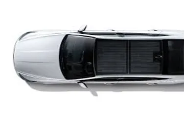
Car roof types:
- Hard top
- Sun roof
- T-top
- Targa top
- Vinyl’s top
- Hardtop
Hardtop is a rigid form of automobile roof, which for modern cars is typically constructed from metal. A hardtop roof can be either fixed (i.e. not removable), detachable for separate storing or retractable within the vehicle itself.
- Sunroof
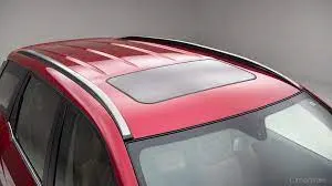
Sunroof is a movable panel that opens to uncover a window in an automobile roof, allowing light and fresh air to enter the passenger compartment. Sunroofs can be manually operated or motor driven, and are available in many shapes, sizes and styles.
- T top
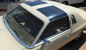
T-top (UK: T-bar) is an automobile roof with a removable panel on each side of a rigid bar running from the center of one structural bar between pillars to the center of the next structural bar. The panels of a traditional T-top are usually made of auto grade safety glass.
- Targa top
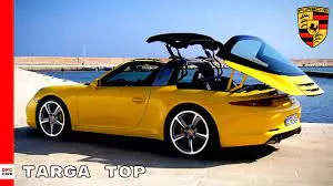
Targa top, or targa for short, is a semi-convertible car body style with a removable roof section and a full width roll bar behind the seats.The rear window is normally fixed, but on some targa models, it is a removable plastic foldable window, making it a convertible-type vehicle.
- Vinyls
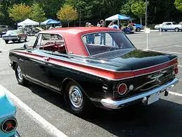
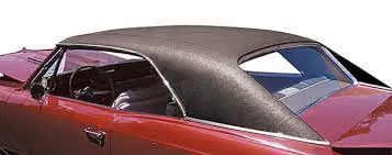
Vinyl roof refers to a vinyl covering for an automobile's top.This covering was originally designed to give the appearance of a convertible to models with a fixed roof and eventually evolved into a styling statement in its own right.
Procedure:
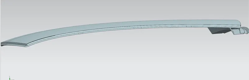
- All dimensions are in mm and Blend radius =3.75mm
Sectional view of the roof given below.
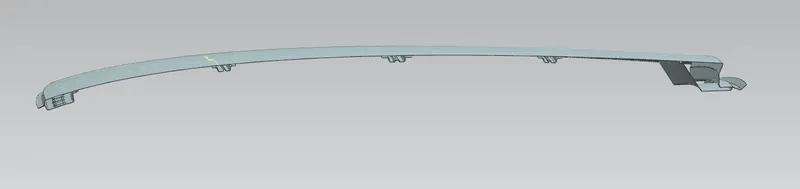
Front roof:
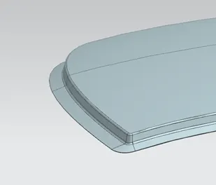
External surface of front roof.
Start with the creation of a roof ditch area with a tool opening angle of 7 degrees.
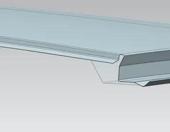
- Rear Roof
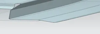
|
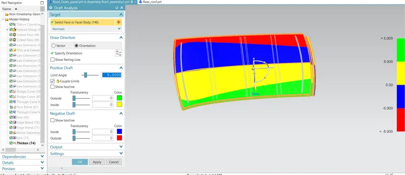
Performed Draft Analysis the part and included the snapshot below: |
Center Roof Rail:
Center Roof Rail is placed at the middle of the roof.
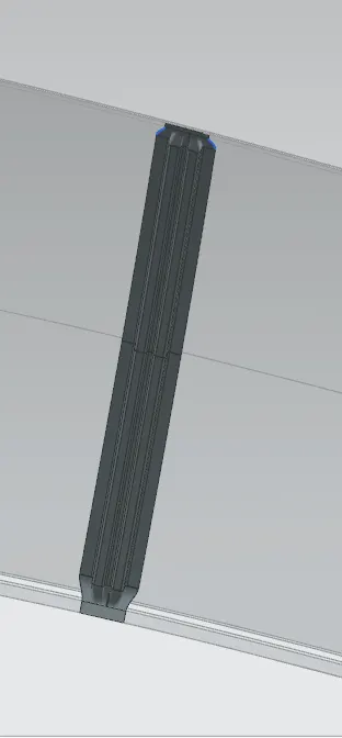
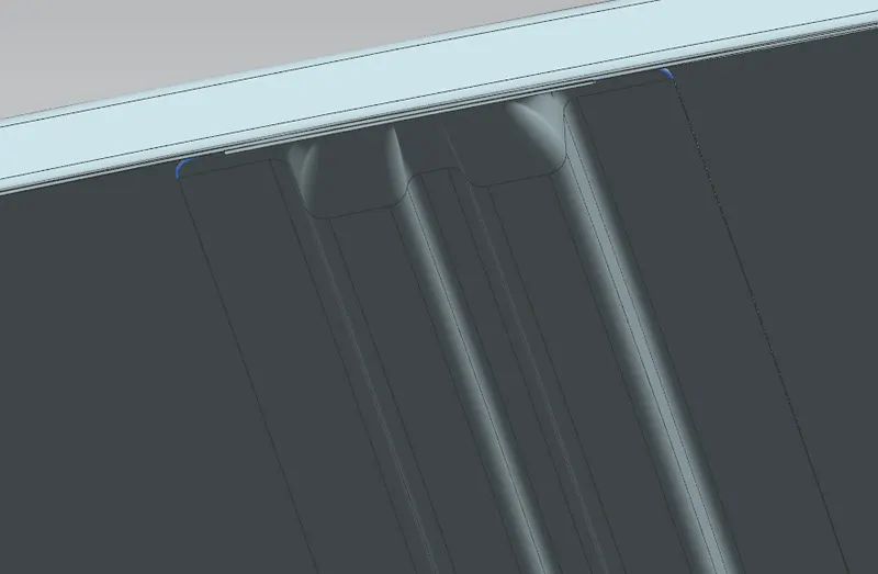
center roof rail assembled with outer panel of the roof.
|
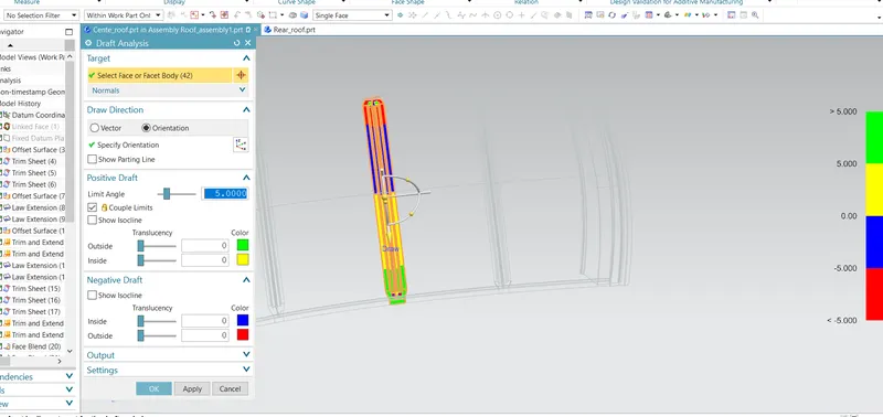
Performed Draft Analysis the part and included the snapshot below: |
Inner Rear Roof Rail:
Rear Roof rail is also the reinforcement for the outer panel and it joins the backdoor and the body side outer. For designing the Rear roof rail also, we have developed a master section based on the functional requirements which are Rear visibility criteria, Rear head room clearance, Tool opening and mastic clearance. See the below image of Rear Roof rail design.
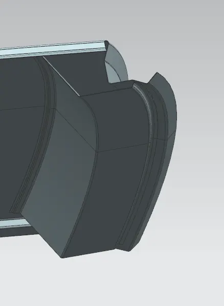
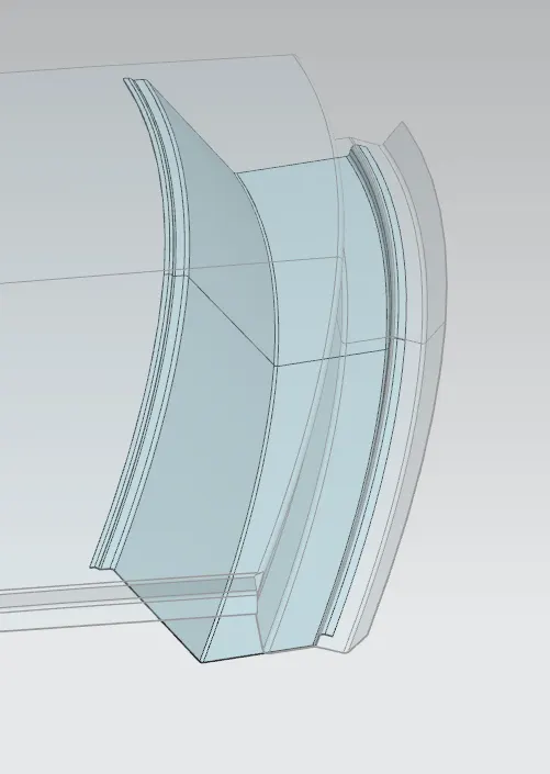
|
Performed Draft Analysis the part and included the snapshot below: |
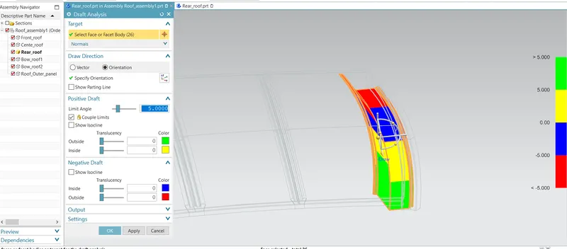
Bow Roof Rails Front and Rear:
Bow Roof Rails are also the reinforcements of outer panel and are used to strengthen the roof panel and these joins to the Roof panel with the help of mastic sealant to the roof panel and connects to the body side using the spot-welding technique. These are designed based on the developed master sections developed using the criteria of Visibility and the head room clearance. And the position of these Bow roofs is mostly recommended to place at the flat portions of the Roof outer panel
Bow Roof 1:
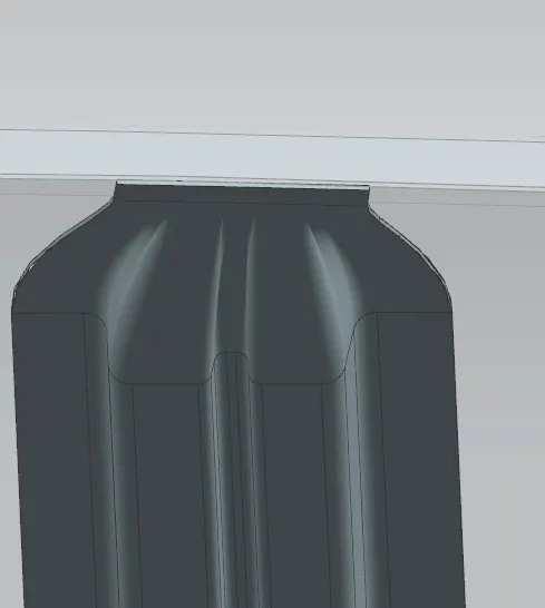
bow roof 1 is placed at front of the roof with the distance of 500mm.
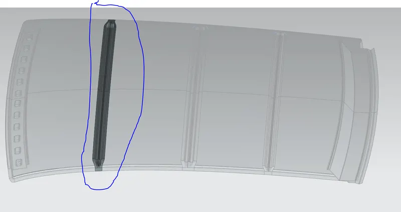
|
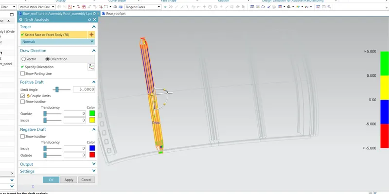
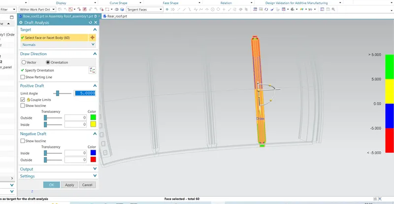
Performed Draft Analysis the part and included the snapshot below: |
Bow Roof 2:
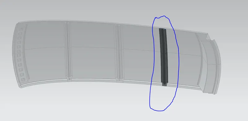
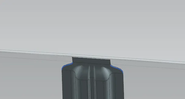
bow roof 2 is placed at front of the roof with the distance of 500mm.
|
Performed Draft Analysis the part and included the snapshot below: |
Front roof inner panel:
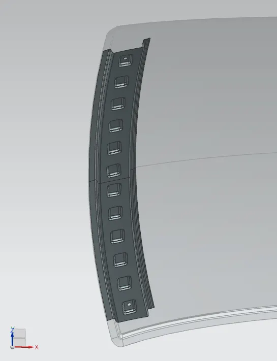
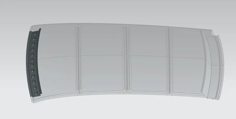
Front Roof rail is the reinforcement for the roof outer panel and as well as it joins the Roof panel with the Windshield glass and body side panel and also supports the bracket map lamp and room lamp mounting. Front roof rail created based on the master section which is developed with above mentioned functional requirements of tool opening angle, required clearance for to join with the windshield glass, visibility criteria, the deepness based on the head room clearances and the clearance mastic joining. See the below master section used for the Front Roof Rail and the Front roof rail design based on the master section
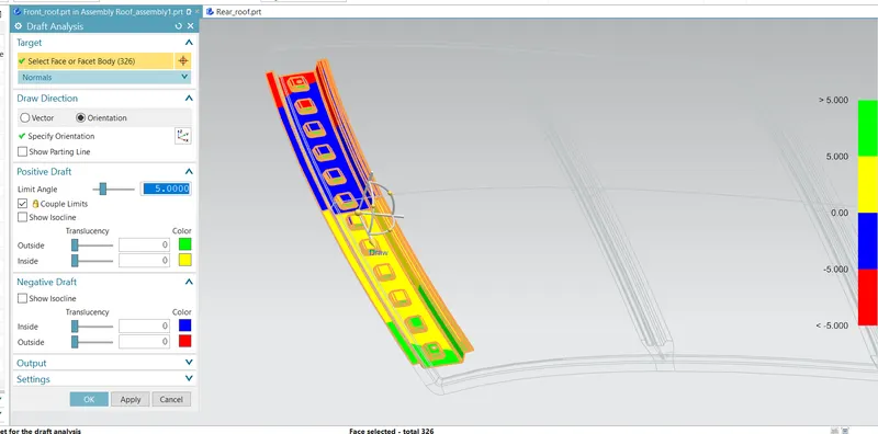
| Performed Draft Analysis the part and included the snapshot below: |
Bow–Roof Prediction Formula,
W = [1.73 x 10^ (-3) x L] + [1.85 x 10^ (-8) x (R^2)/t] + [ 1.10x10^ (-3) x l] - 2.68
Where,
L = Roof Length in X-Direction[mm](Roof dimension in 0-Y)
R = Roof curvature
R = 2(Rx*Ry)/(Rx+Ry)
Rx = X curvature
Ry = Y curvature
t = Roof plate thickness [mm]
l = Bow Roof Span [mm]
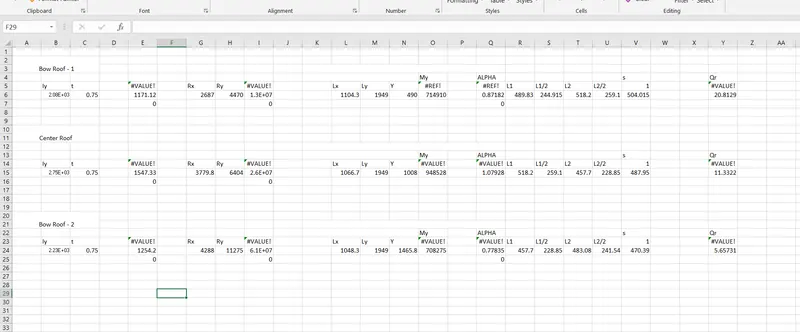
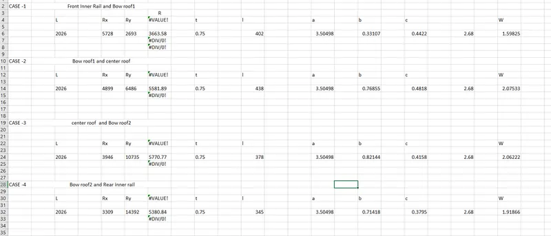
using Bow–Roof Prediction Formula calculated and below values are came and excel file is attached to the challenge.
Judgment Condition
OK< 2.7
Justicfication is ok because all values came less than 2.7 and the values are shown above snap. excel file attached to the challenge.
1. W value of Front Inner Rail and Bow roof1 = 1.59825
2. W value of Bow roof1 and center roof = 2.07533
3. W value of center roof and Bow roof2 = 2.06222
4. W value of Bow roof2 and Rear inner rail = 1.91866
Snow Load Prediction Formula
Qr = [Iy x t2] / [α x s x [(Rx + Ry)/2]2 x 10-8]
Note: The Qr value given over here is correct. There was a typo error in the formula given in the video.
Where,
α = My x Lx2 x 10-12 , My = Y(Ly-Y)
t = Roof plate thickness [mm]
Ly = Distance between the front and rear roof Rails on the Vehicle along with 0Y[mm]
Length of Roof panel with the center point between Roof rail Front /Rear as the front and rear reference point.
Lx = Distance between the Left and Right end of the roof on the Roof BOW [mm]
The width of the roof panel is exposed on the surface.
Y = Distance front Front Roof Rail to Roof BOW[mm]
s = Distance for which Roof BOW bears divided load [mm]
s = L1/2 + L2/2
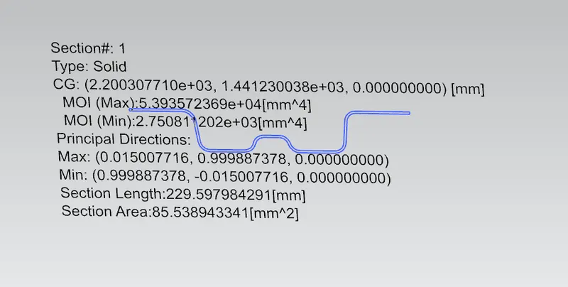
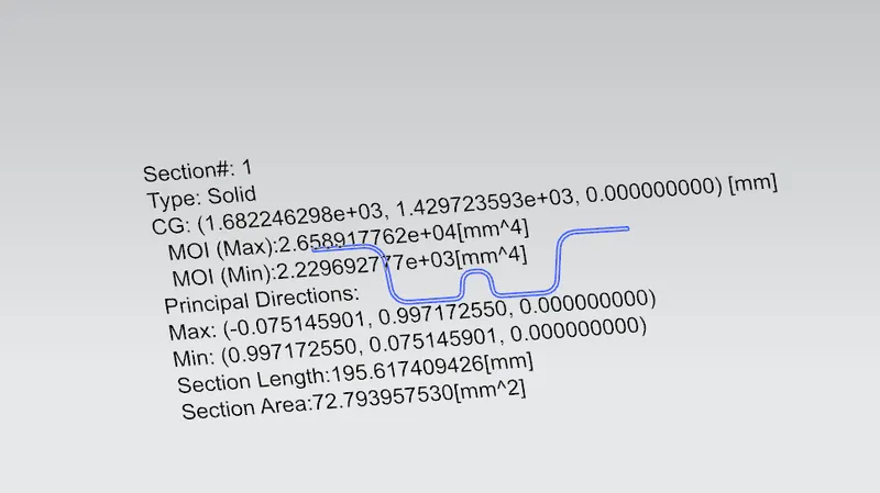
Iy = Geometrical moment of inertia of Roof BOW (Y cross-section )[mm4]
Rx = Lateral direction curvature radius of roof panel Y cross-section on Roof BOW [mm]
Roof panel curvature Radius of the Length Lx in Front view
Ry = Longitudinal Direction curvature radius of the Roof panel X cross-section on Roof BOW [mm]
Roof panel X curvature radius of length s in Side view
Judgment condition
Qr ≥ 3.1
Answer:
here Iy value will do for 3 sections they are Bow roof 1 and 2, center roof.
because we are not considering s values for 4th condition.
Lx values for 3 sections.
Ly value will be same for all sections.
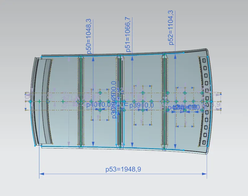
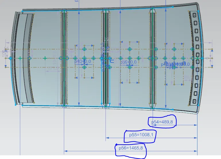
Y values are given below.
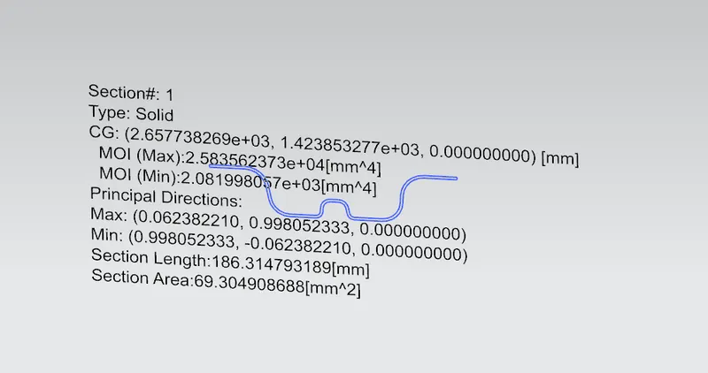
Bow roof 1 Moment of inertia = 2.081998057e+03
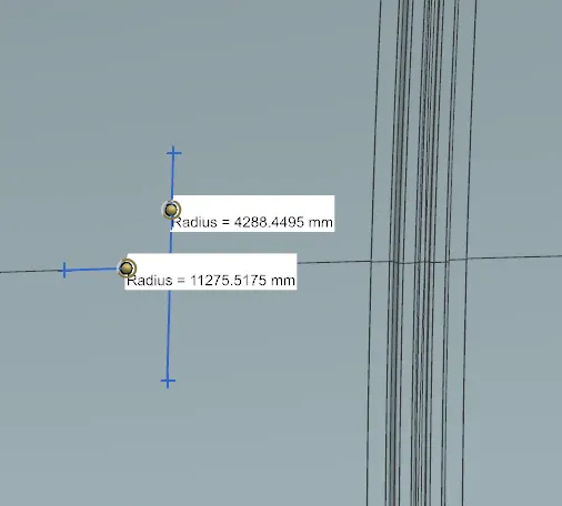
Rx and Ry values:
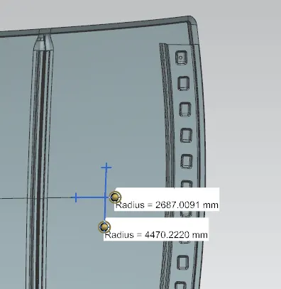
Center roof Moment of inertia = 2.750811202e+03[mm^4]
Rx and Ry values:
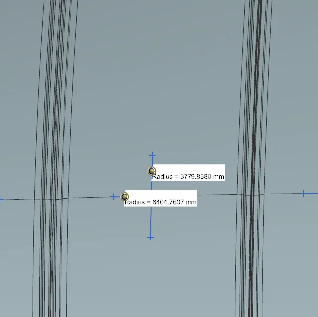
Bow roof 2 Moment of inertia = 2.229692777e+03[mm^4]
Rx and Ry values:
Judgment condition
Qr ≥ 3.1
Snow Load Prediction Formula is ok because in 3 sections Qr value is >= 3.1
Calculations are in excel sheet and it is given in ZIP file.