Roof Design
AUTOMOTIVE SHEETMETAL ROOF DESIGN USING NX CAD
Objective:
- Perform Roof Sheetmetal design by creating front roof rail, rear roof rail, bow roof front, bow roof rear, center roof reinforcement from the given styling surface
- Perform curvature study on Roof using Heat distortion and Snow load criteria to determine the position of the Bow roofs.
Introduction
Car Roof :
An automobile roof is the portion that is above the passenger compartment, protecting the vehicle occupants from sun, wind, rain, and other external elements and crash. The roof is the structure above the windshield glass having the reinforcements to provide strength to the overall structure and to withstand overhead loads like snow.
Reinforcement :
If the roof is flat, it is very weak and is not able to withstand the forces like snow, so to increase the strength of the roof these reinforcements like front roof rail, central roof rail, rear roof rail, and bow roof rail are introduced and joined to the flat surface of the roof with the different joining process like mastic and spot welding. Front roof and rear roof rails are fixed to the ditch area using spot weld operation. But front, rear bow roof and center roof rails are fixed to roof using mastic sealants.
Roof Crush test :
Roof crush test is the design given by the IIHS ( insurance institute of highway safety ). After analyzing many accidents IIHS has then fixed some regulations for how to perform the crush test .
IIHS gives the rating based up on this test . For this they consider two points while giving the rating
- How fast the car can reforms to its original shape after the roll over and
- How deep is the protrusion after the roll over
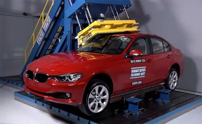
To minimize the protrusion into the occupant compartment , so that the seat belts and air bags can do there job in protecting the occupant
The load is applied in such a way that 50 is tilted from the front end to the rear end and the load will be in 1800 mm in length and 750 mm in width . The load is applied at the position of 250 from the flatness of the roof . The load is applied on the roof for almost 120 sec and the crush speed at which the load applied is 13 mm/sec or less than that
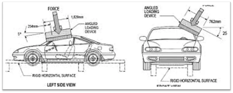
If the displacements goes above the requirements level then we have to increase the bow roof thickness or add more mastics points to increase the strength . the stronger the roof the better it can protect the occupants in the roll over crashes.
Roof Design:
Master section data for front roof rail, rear roof rail, bow roof front, bow roof rear, Center roof rail and reinforcement are used
We can design the Roof, front roof rail, rear roof rail, bow roof, center reinforcement rails are creating with help of styling surface for roof.
1) Ditch Area
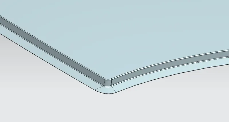
ditch area is created with help of the given surface. We have to create the extension sheet using law extension command with minimum 15mm, and give the draft angle of minimum 7 degree considering the following drawing operation as prescribed in the given master section
2) Front & Rear Roof Rail
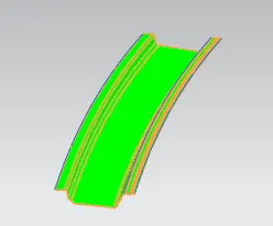
When considering the parameters of roof rail, length, proper draft angle and blend radius mentioned in master section is followed. Front section of front roof rails isspot welded to the front ditch area and other end is fixed with help of mastic sealants.
sewing the geometry and thickening upward direction of the mentioned thickness and is checked for draft analysis
Sheetmetal thickness t = 0.75mm
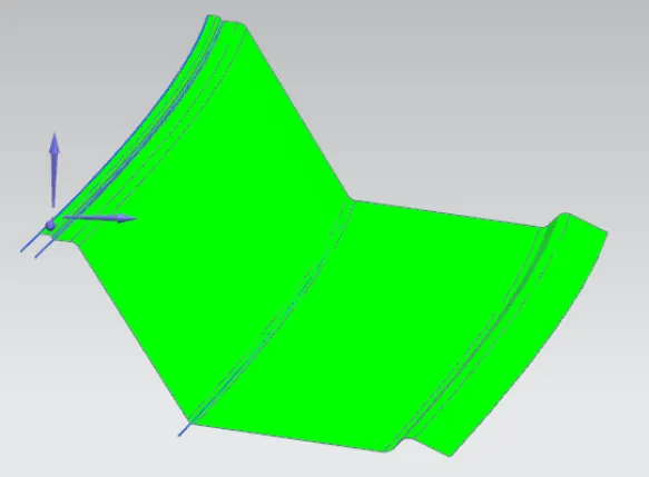
Front Roof rail Rear roof rail
3) Bow roof
The bow roofs are given to the improve the load bearing capacity of the roof structure. When number of bow roofs are given by the roof dimension. Longer the roof area we have to give the more bow roof to the structure.
Positioning of the bow roofs are decided by the curvature study. The Heat distortion and Snow load criteria are checked to analyze the bow roof position by various condition.
Thickness of the Bow roof is 0.75mm and checked for draft analysis
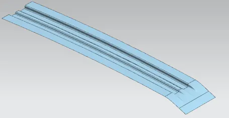
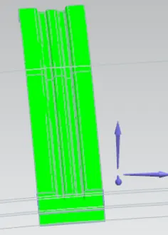
4) Center Roof Rail
Reinforcement Center roof rail is effective support to the flat area structure roof. Because of center area of roof is more susceptible to failure under action of load. Usually, Reinforcement center roof rails are fixed at the center of the roof for connecting to the B – Pillar support structure, it will used for roll-over test.
Thickness of the Reinforcement center roof rail is 0.75mm.
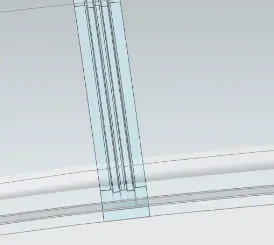
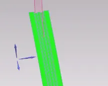
Moment of inertia of the section:
1)BOW roof front:
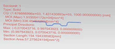
Moment of inertia (Min), Imin = 336.464 mm4
2)Center roof rail
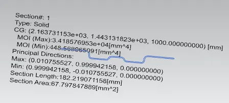
Moment of inertia (Min), Imin = 448.5 mm4
2)BOW roof rear
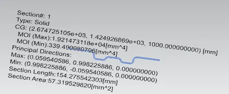
Moment of inertia (Min), Imin = 339.4909 mm4
Curvature Study on the roof:
1) Heat Distortion Criteria
The heat distortion study the plays an important role in Sheetmetal application. Heat distortion is temperature limit above which material cannot be used for structural application. This study is useful to find where the material starts to soften when exposed to a fixed load at elevated temperature. In order to avoid the bending, damage to the roof based on the heat distortion temperature. This study will provide the which position of the bow roof give enough strengthen to roof.
Bow Roof Prediction Formula:
W = [1.73 x 10^(-3) x L] + [1.85 x 10^(-8) x (R^2)/2] + [1.10 x 10^(-3) x I]-2.68
Judgement Condition: OK<2.7>3.1
Where,
L= Roof Length in X- direction [mm](Roof Dimension in 0-Y)
R = Roof curvature
R = 2(RX*RY)/(RX+RY)
RX = X Curvature
RY = Y Curvature
t = Roof plate thickness [mm]
I = Bow roof span [mm]
Thickness for the Roof(t):
Roof Outer Panel, t= 0.75mm
Front Roof Rail, t = 0.75mm
Rear Roof Rail, t = 0.75mm
Bow Roof Rail Front, t = 0.75mm
Bow Roof Rail Rear, t = 0.75mm
Reinforcement roof rail, t = 0.75mm
Procedure:
- From 0-Y axis, at -3Y about distance 300mm is drawn parallel on the perpendicular plane. After that 100mm lines are offset to either side of -3Y line. Now center lines are drawn between each adjacent roof rail edges respectively. Intersection points are marked on the sketch. Make all geometry lines are construction lines except points.
- Project the intersection points on sketch to the Roof surface.
- Join the intersection points in roof surface using the three point arc command an measure the radius using the local radius command
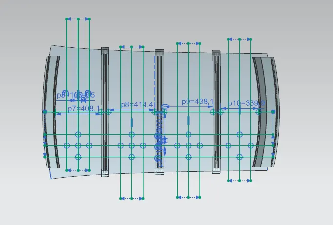
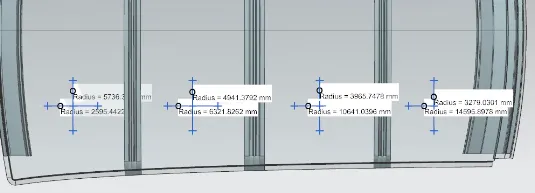
Substituting all the required values measured into the formula, we get,

From the above table we, conclude that all the values are of W< 2.7
So, that all bow roofs areas are placed at the right place.
2)Snow Load criteria
Snow load criteria study is used to check the durability of the roof to withstand the snow fall on the roof and reflex it is original shape without any permanent deformation after load being removed.
Qr = [IY x t2] / [α x s x [(RX + RY)/2]2 x 10-8]
Where,
α = My x LX2 x10-12, My = Y(Ly–Y)
Judgement condition = Qr > 3.1
t = Roof plate thickness[mm]
LY = Distance between the front and rear roof rails on the vehicle along with 0Y[MM],
LX= Distance between the left and right end of the roof on the roof bow[mm],
Y = Distance between Front roof rails to roof bow [mm],
s = Distance for which roof bow bears divided load [mm],
s = L1/2 + L2/2
Iy = Geometrical moment of inertia of roof bow (Y cross – section) [mm4],
RX = Lateral direction curvature radius of roof panel Y cross section on roof bow [mm4],
RY = Longitudinal direction curvature radius of the roof panel X cross section on roof bow[mm4],
Procedure:
- At 0-Y axis on perpendicular plane to roof. Draw 100mm lines offset to either side of the of 0Y axis line. Now center lines are drawn between each adjacent roof rail respective. Intersection points are marked on the sketch. Make all the geometry in construction lines except points.
- Project the intersection points in the sketch are projected to roof surface.
- Join the project points using arc curve and measure the radius value using minimum radius comment.
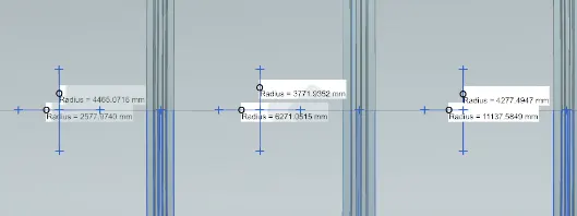
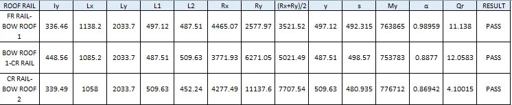
If roof structure pass to the snow load condition. They, must have Qr values from above 3.1.
Qr > 3.1
Heat distortion and snow load criteria passes the current postion, so position of the bow roofs and center reinforcement roofs placed are within the limit
Conclusion :
Hence the roof, front roof rail, bow roof rails, central roof rails, and rear roof rails are designed by following the master sections, Curvature study and draft analysis is carried out to check manufacturability of the part