Hood design-Week 2
AUTOMOBILE HOOD DESIGN
Aim:
To design and develop the inner panel of an automobile hood based on the given part file of Hood outer panel, striker and Hinge assembly considering the industrial standard using SIEMENS NX
Abstract:
The hood or bonnet is the hinged cover over the engine of vehicles that allows access to the engine compartment, or trunk for maintenance and repair. On front-mounted engine cars, the hood may be hinged at either the front or the rear edge, or in earlier models, it may be split into two sections, one each side, each hinged along the centreline. A further variant combines the bonnet and wheel arches into one section and allows the entire front bodywork to tilt forwards around a pivot near the front of the vehicle.
The report deals with the detailed steps and procedure followed while developing the hood assembly using NX CAD. Using the skin data of outer panel provided and master section as input, the inner panel is created incorporating features like embossments and mastic points. Assembly is done by tracing the trajectory of latch and striker with respect to the hinge axis for proper functioning of Hood
Design Parameters:
The Hood consists of an outer panel and an inner panel. The inner panel provides strength and support, where the outer panel is a metal cover that has styling factors. While designing the hood, a design engineer needs to make sure that the following design requirements are followed.
Pedestrian safety
Occupant safety
Vehicle quality
Aesthetics
Manufacturability
Hood components:
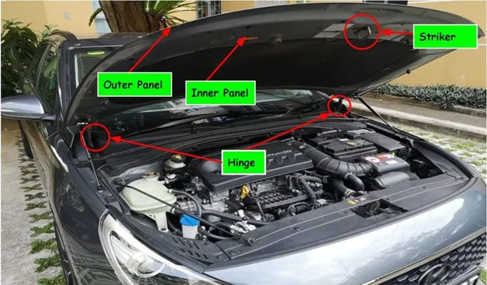
A hood mainly consist of:
- Outer Panel
- Inner Panel
- Latch and Striker
- Hinge
- Stay Rod
Safety Considerations:
Pedestrian safety & Occupant safety are the most important factors while designing Hood. Euro NCAP is a voluntary vehicle safety rating system that provides manufacturers and consumers with information regarding the safety of passenger vehicles. The more stars, the better safety it will be provided to the customer. Thus a design engineer must need to follow these requirements to provide better safety to the customers.
The most important safety requirement to be considered while designing the Hood is the front collision requirements for the adults and child head. Most pedestrian accidents occur within city areas where speeds are moderate. The head, the lower body, and the legs are amongst the most frequently injured body regions. To estimate the potential risk of head injury in the event of a vehicle striking an adult or a child, a series of impact tests are carried out at 40 km/h using an adult or child head form impactor. Impact sites are then assessed and the protection offered is rated as good, adequate, marginal, weak, or poor.
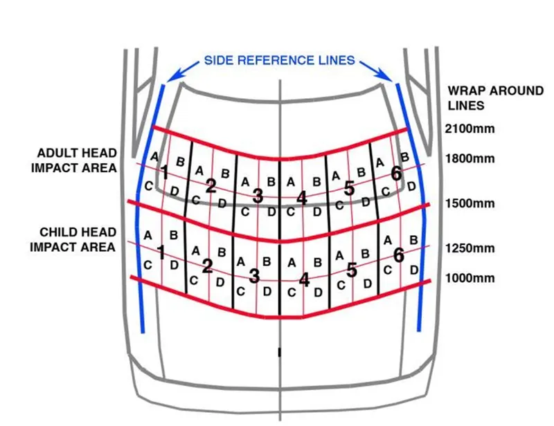
As we can see in this above diagram which shows the impact zone for child and adult head, so we have to design the inner panel such that there should be minimal contact between head and inner panel, so we have to cut some inner panel sheet in such a way that the strength should not decrease and there should less impact on the head.
he hood of most vehicles is usually fabricated from sheet metal, which is a compliant energy-absorbing structure that poses a comparatively small threat. Most serious head injuries occur when there is insufficient clearance between the hood and the stiff underlying engine components. A gap of approximately 10 cm is usually enough to allow the pedestrian’s head to have a controlled deceleration and a significantly reduced risk of death. Most limb injuries occur due to a direct blow from the bumper and the leading edge of the hood. Wrap Around Distance (WAD) is the distance from the ground level to the end of the hood as shown in the image.
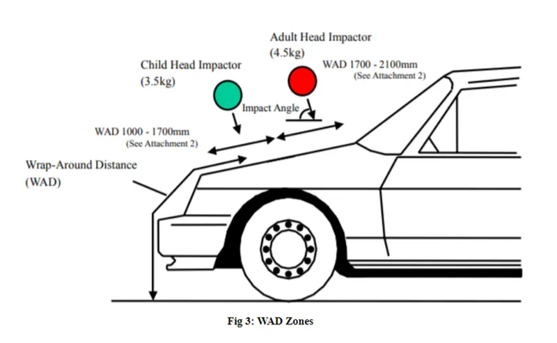
There are two main zones that are considered while the designing stage; the Child head impact zone (1000mm to 1700mm WAD) and the Adult head impact zone. (1700mm to 2100mm WAD). If the side reference line is on the fender, the WAD will be more and the impact zone will be less and vice versa.
DESIGN PROCEDURE:
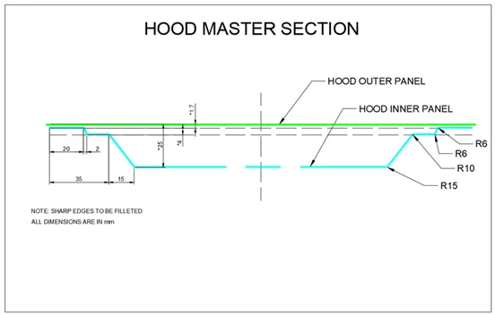
The design of inner panel is based on the given master section as shown in the image:
Steps:
1)Import the file: The given input file has to be made in an assembly named Hood Assembly under which all parts can be created. First create an assembly tab, and using the Add or Create new options available in the assembly tab. Only the inner panel folder tab has to be created, while all other components are given as input
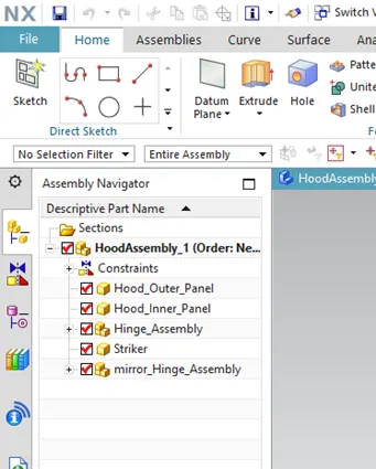
2)Start with the design of inner panel from the given surface of outer panel of the hood. Make hood_inner_panel as the Work part
3)Trim the surface into half w.r.t XC plane using the Trim body tool in the Surface panel
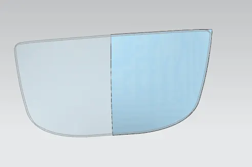
4)Offset the outer panel (working surface) 1.7 mm downwards as per the mastersection. Using the Offset cuve in face, create a curve 20mm from the boundary of the surface and using the Trim Sheet tool available, trim the portion as required. Also from the working surface, create an offset of 4mm downwards and with a curve 22mm from the boundary has to be created. Trim it in the opposite direction of that done earlier
5)Create surface between two flanges using through curve option
6)Offset surface to 25mm and use offset curve to 50mm
7)Use law extension and by using trim and extend the surface between second and third flange is made where a positive draft angle is given,use face blend option and use radius as given in master section
8)In order to create the Emboss, a closed profile sketch is needed which has to be drawn by giving gaps for latch and hinge placement. Sketch the curve and project the curve onto the face,use the emboss tool
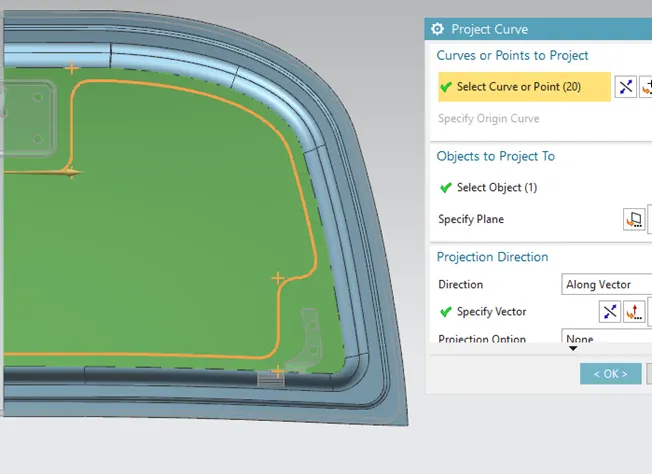
9)Also another sketch has to be drawn to remove the material inside the inner panel and embossement with accomodaton for mastic sealants are made for the inner panel
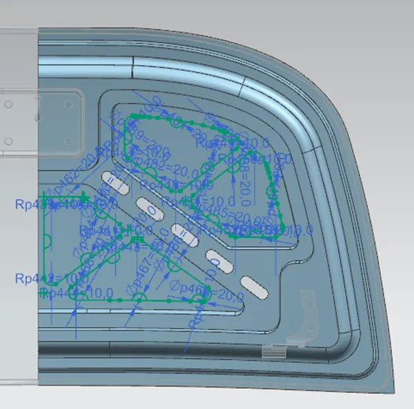
10)All faces and corners has to given with face blend and edge blend respectivily
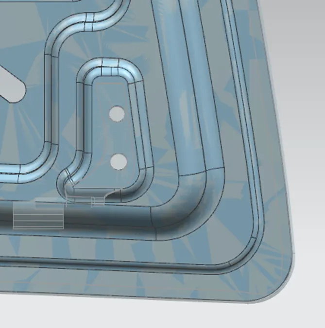
11) For hinge emboss, First move the hinge component close to the inner panel and in the correct position. Now create a datum plane which is parallel to the face of hinge, sketch the shape of emboss required, with the created datum plane create an Emboss in the face of inner panel and gie necessary edge blend.using wave geometry linker create the holes by composite curve and trim the sheet to make holes
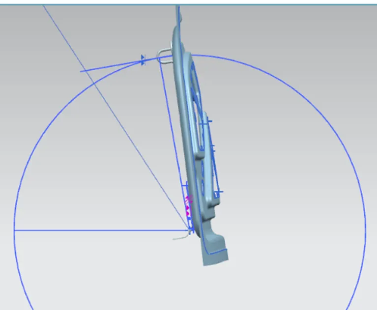
12) As one side of hinge assembly is finished, the other one in the opposite side is mirrored using Mirror Assembly tool in the Assembly panel. Create a line passing through the hinge axis For that, create a midpoint line in between the hinge assembly so that the created point act as centre point and draw a cicle with the radius through the striker so that the opening and closing of the hood depends on the path of circle. Draw a tangent line from the circle and draw another line parallel to the striker locally. Make this two lines overlap using the touch align constraint tool, so that the striker is in the exact position.
13) Now to create the striker emboss, use the wave geometry linker to exract a surface from the striker and with the extracted surface, create an Emboss from the inner panel to the linked body
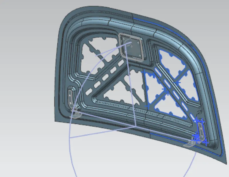
14)After the striker and Hinge is assembled , use the mirrror geometry to mirror the part so that complete inner panel is created, Now Sew both the parts and inorder to cross check or examine use Examine geomtery tool, which will notify any errors or gaps in the model.
15)Thicken the part for an offset distance of 0.75mm.
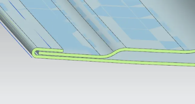
16)To create the hemming,make outer panel as the work part, first offset the outer panel downwards to the required dimension inorder to create the bottom face of the Hem by proviing the thickness and allowances.Use law extension to create the boundary of hem and the lower length and use trim sheet to trim according to the dimension
17)Using the face blend with three face helps to create the Hem in the outer panel. Also in the hem, proper relief has to be given in the corners and check for any interference
18) Thicken the outer panel with the same offset distance of 0.75mm.
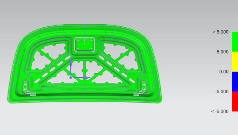
19)The last step in this operation is to check the draft for inner panel by creating a Datum CSYS plane and using the draft analysis tool, and make the limit angle to a minimum of 5 degrees and check whether the draft is positive
Manufacturing Process:
The manufacturing process involves turning raw materials into finished products which are used for some purpose. The economics of the manufacturing operation is a very important consideration. To be viable in the modern environment, a product has to be competitively priced besides having functional and aesthetic appeal. There are different processes available for manufacture. These are classified as Casting Process, Forming Process, Fabrication Process, Material Removal Process.
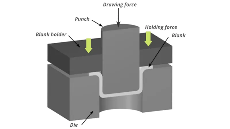
Drawing: is the process of making cuts, shells, and similar articles from metal blanks. Drawing when cup height is more than half the diameter is termed deep drawing. Ductile materials are easier to be drawn into deeper cups. In deep drawing, because of the radial flow of material, the sidewalls increase in thickness as the height is increased. There would be a slight thinning of metal at the bottom corners.
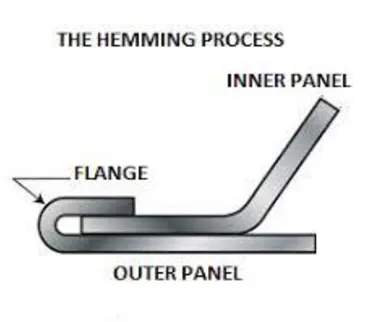
Hemming: it is a sheet metal forming process in which sheets are joined by bending it usually to 180 degrees. Automotive body panels and automotive parts such as deck lids, trunk lids, doors, hoods, and tailgates are forming by the hemming process.
---------------------------------------------------------------------------------------------------------------------------