Roof Design
ROOF CHALLENGE
Roof
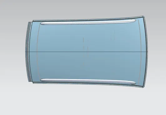
- An automobile roof or car top is the portion of an automobile that sits above the passenger compartment, protecting the vehicle occupants from sun, wind, rain, and other external elements.
DESIGN CRITERIA FOR DESIGNING ROOF
- Visibility criteria (front & back)
- head clearance
- curvature study
- heat distortion & snow load criteria
The roof consists of various assemblies
- Front rail
- Rear rail
- Bow between front rail and center bow roof
- Bow roof between rear rail and center rail roof
FRONT RAIL
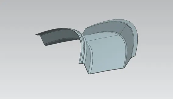
- The front roof rail provides provision for the windshield glasses. Visibility criteria and headroom clearance have to be followed while designing the front roof rail. Provision for windshield mounting and inside rearview mirror is provided on the front roof rail.
REAR RAIL
- The Rear roof rail has hinge mounting for the back door. It is attached at the portion where the back door meets with the roof.
BOW ROOF
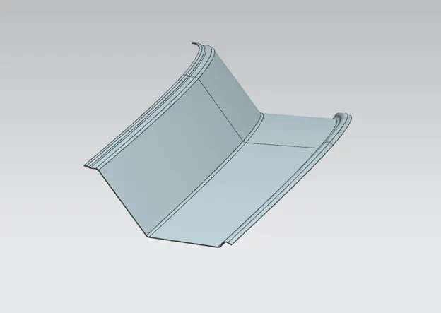
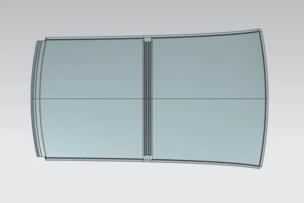
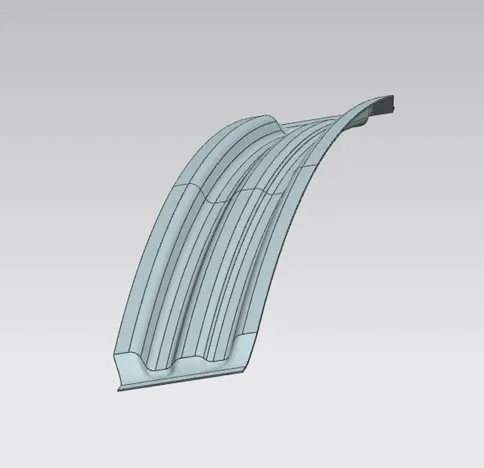
- Bow roofs are provided in between the front roof rail and center roof rail as well as the Rear roof rail and center roof rail. They are provided to enhance the localized strength of the roof and are attached directly to the bottom of the roof with the help of Mastics.
CENTRE BOW ROOF
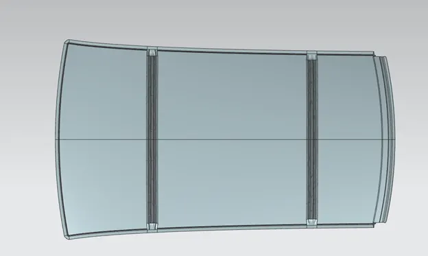
- Reinforcement center or center roof rail is used as a cross member between Left hand and right-hand bodysides.
To joining this different assemblies there are two types of techniques is used:
- Spot welding
- Mastics
SPOT WELDING
Spot welding (also known as resistance spot welding) is a resistance welding process. This welding process is used primarily for welding two or more metal sheets together by applying pressure and heat from an electric current to the weld area.
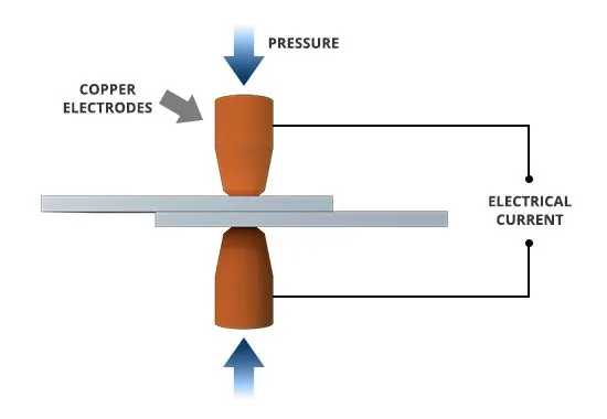
- Spot welding technique is used to attach front and rear rail to the roof because front roof rail is going to be covered by the wind shield of the car and the rear rail is goin to be covered by the back door component of the cars , so the asthetics of the car is not going to be affected as it was covered
- To perform spot welding there mus be no gaps between the roof ditch area and rail
MASTICS
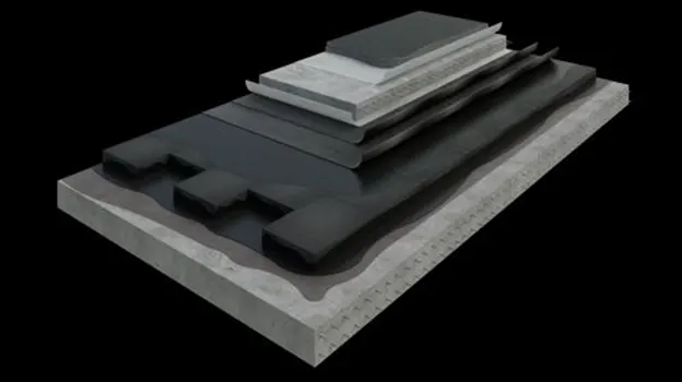
- The mastics are one of the rubber kind of material which is used to attach the assemblies from inside so the asthetics of the car may not be affected from the out side.
- To perform mastics the components must be maintained by the clearance of 5MM
Roll Over Test on Roof
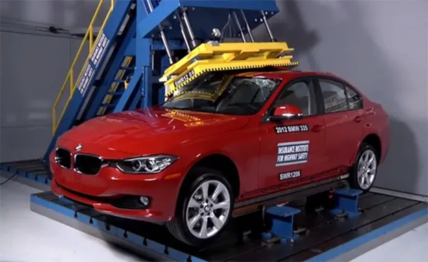
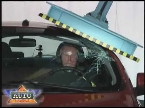
- The rollover test is given by the Insurance Institute of highway safety ( IIHS). After analyzing many accidents IIHS has fixed some regulations about how to perform the test.
- IIHS rating is based on the following things which are how fast a car can reform its original shape after rollover and how deep a protrusion is.
- The aim of this test is to minimize the protrusion of the roof.
- Two conditions need to be followed while performing this test. One is to lock all the doors of the car properly and the second is to close all the windows of a car.
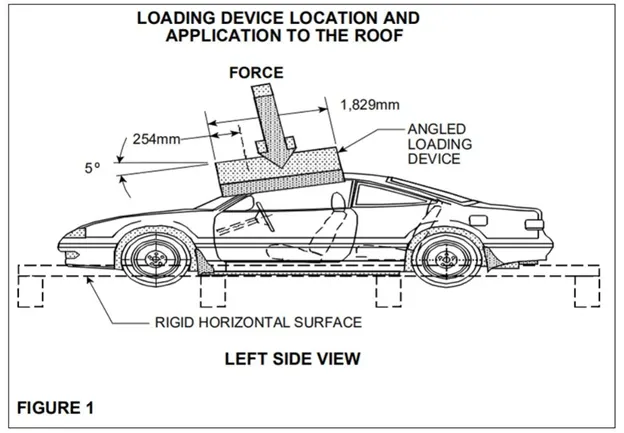
- Also, it is mandatory to fix the chassis on the hard lever surface horizontally.
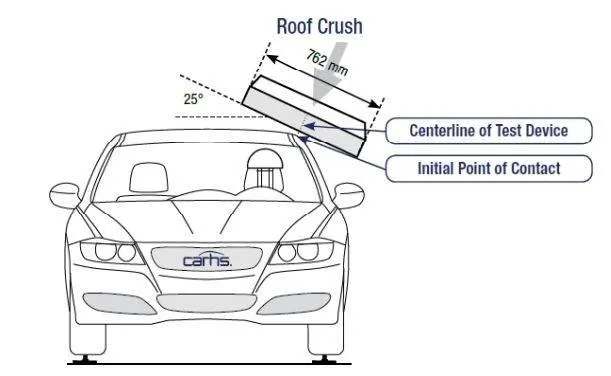
- Load is applied at 25 degrees tilt when view from the front over the length of 762 mm.
- Load is applied at 5 degrees tilt when view from the side, over the length of 1829 mm.
Design Considerations
- Clearance of 5 mm should be present between outer roof rail and Front roof rail, Rear roof rail, Bow roof, and Reinforcement center where mastics are used for adhesion.
- Thickness for all sheet metal parts - 0.75 mm.
- All edges should have fillets and there should not be any sharp edges present.
- A minimum draft angle of 7 degrees must maintained
HEAT DISTORTION CRITERIA:
- Heat distortion temperature is the temperature at which the metal softens and deforms under a specific load. This study is done to check the ability of the roof to withstand high temperature with respect to the positioning of the reinforcements which contribute to increased strength.
Bow–Roof Prediction Formula
W = [1.73 x 10^(-3) x L] + [1.85 x 10^(-8) x (R^2)/t] + [ 1.10x10^(-3) x l] - 2.68
Where,
L = Roof Length in X-Direction[mm](Roof dimension in 0-Y)
R = Roof curvature
R = 2(Rx*Ry)/(Rx+Ry)
Rx = X curvature
Ry = Y curvature
t = Roof plate thickness [mm]
l = Bow Roof Span [mm]
Judgment Condition
OK< 2.7
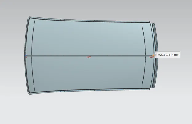
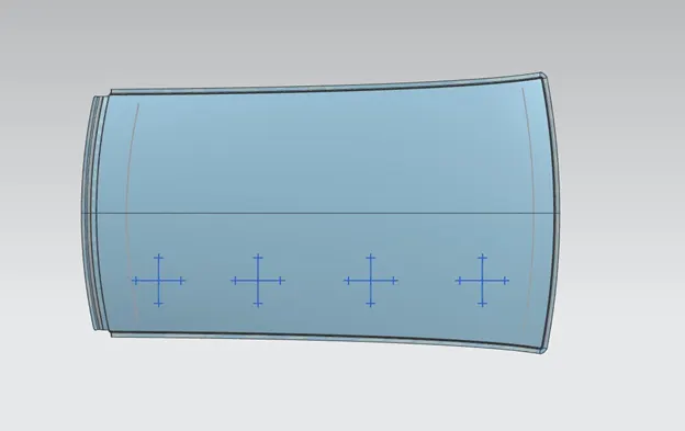

JUDGEMENT CONDITION
- From the above tabular column, the design satisfies the judgement condition which is OK< 2.7
SNOW LOAD CRITERIA:
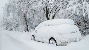
- The purpose behind this analysis is to check the strength of the roof when snow is present on it acting as a load.
- A roof should be designed in such a way that it should rebound to its original shape after the removal of snow.
Snow Load Prediction Formula
Qr = [Iy x t2] / [α x s x [(Rx + Ry)/2]2 x 10-8]
Note: The Qr value given over here is correct. There was a typo error in the formula given in the video.
Where,
α = My x Lx2 x 10-12, My = Y(Ly-Y)
t = Roof plate thickness [mm]
Ly = Distance between the front and rear roof Rails on the Vehicle along with 0Y[mm]
Length of Roof panel with the center point between Roof rail Front /Rear as the front and rear reference point.
Lx = Distance between the Left and Right end of the roof on the Roof BOW [mm]
The width of the roof panel is exposed on the surface.
Y = Distance front Front Roof Rail to Roof BOW [mm]
s = Distance for which Roof BOW bears divided load [mm]
s = L1/2 + L2/2
Iy = Geometrical moment of inertia of Roof BOW (Y cross-section) [mm4]
Rx = Lateral direction curvature radius of roof panel Y cross-section on Roof BOW [mm]
Roof panel curvature Radius of the Length Lx in Front view
Ry = Longitudinal Direction curvature radius of the Roof panel X cross-section on Roof BOW [mm]
Roof panel X curvature radius of length s in Side view
Judgment condition
Qr ≥ 3.1
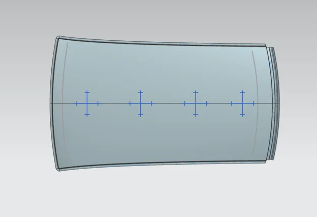
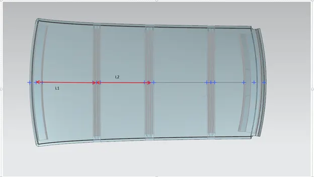
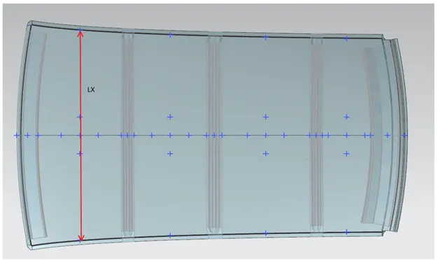
Iy for bow roof 1
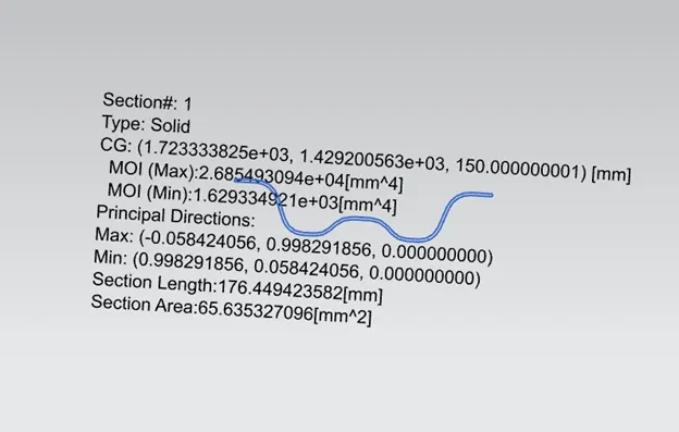
Iy for centre roof
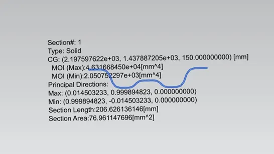
Iy for bow roof 2
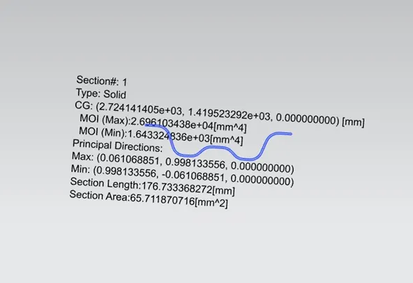

Judgment Condition
- From the above tabular the design satisfies all of the judgement condition that is Qr ≥ 3.1
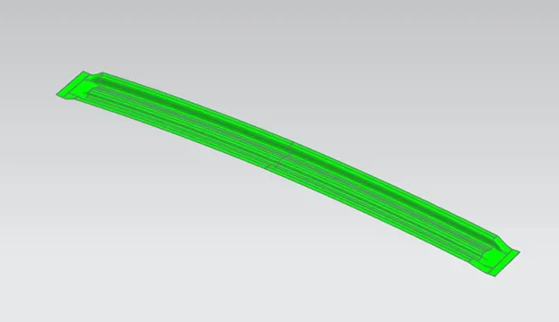
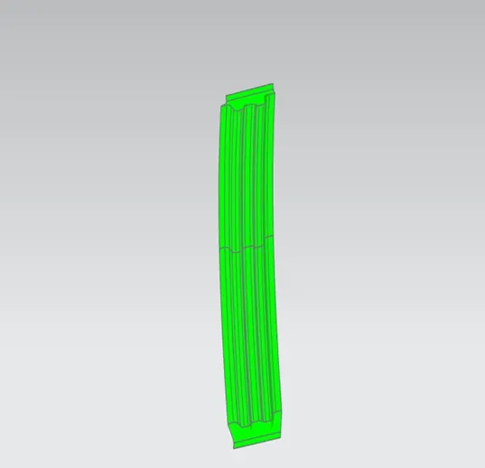
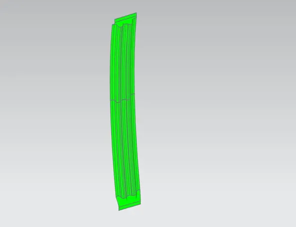
DRAFT ANALYSIS
The Draft Analysis allows the user to easily analyze a part for proper draft angle. A Draft Angle describes the amount of taper for molded or cast parts perpendicular to the parting line.
FOR BOW ROOF 1
CENTRE ROOF
BOW ROOF 2
Conclusion:
- Roof assembly has been made successfully by following engineering standard, master section and styling surface given by styling team.
- For roof assembly heat distortion criteria and snow load criteria has been successfully passed.
- If one of the is failed embosses must be provided to increase the area of the surface to increase more strength of the roof.
- Draft analysis has been carried out to check manufacturing feasibility.
- Designed part will be submitted to CAE team to carry out further analysis to improve the design.