Roof Design
INTRODUCTION
An automobile roof or car top is the portion of an automobile that sits above the passenger compartment, protecting the vehicle occupants from sun, wind, rain, and other external elements.
OBJECTIVE
The mian objective of this project is to understand the design process to design the roof with all the roof rails and to understand the calculations behind it. We also get to learn about the different tools used in NX cad for designing.
DESCRIPTION
DESIGN CONSIDERATION-
-
Visibility criteria
-
Head clearance
-
Curvature study
-
Hear distortion and snow load criteria
-
Draft analysis.
Components of roof-
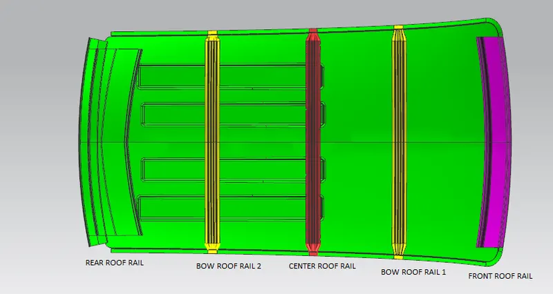
1.Front Roof Rail-
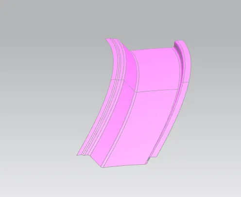
The front roof rail is located on the front of the roof where the wind shield joins with the roof. The visibility criteria and the head room clearance of the passenger are taken into consideration for the bottom flange. One end of the rail is joined using spot welding while the other end is joined with the roof using mastic sealants for increased strength.
2.Bow roof 1-
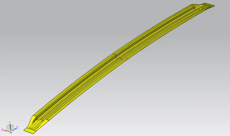
Bow roof is an additional siffening member for the roof to increase the strength and so that it can satisfy the norms. Both the ends are joined together using mastic sealants to increase strenght and also since this would not affect the styling of the roof.
3.Centre Roof Rail-
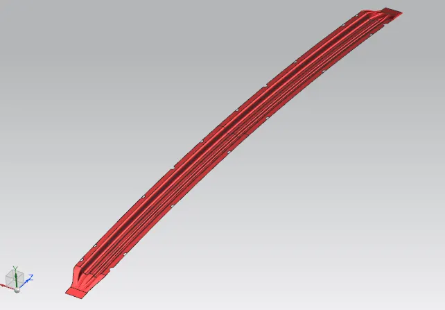
Centre Roof rail or the reinforcement centre is located at the centre of the roof . The cross section of this is more since it needs to provide more strength to the roof. Here both are ends are joined together using mastic sealants.
4.Bow roof 2-
This bow roof also have the same purpose as that of the first one. This one is located between the centre bow roof and rear roof rail.
5.Rear Roof Rail.
This roof rail joins with the back door and the roof. Inputs from the backdoor are taken into consideration for designing this roof rail.
Here one end is joined using spot welding while the other end is joined using mastic sealants
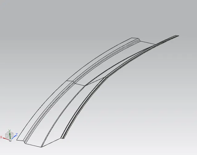
We then also make the ditch area around the roof.
Ditch area the extended portion of the main roof concealed by other BIW panels.
CALCULATIONS
Heat Distortion Curvature Study-
This study is used to find out and predict the heat distortion temperature at where the material starts to soften when exposed to a fixed load. So in order to avoid bending or damage of the roof based on this calculation we will decide the position on the roof bows on the roof.
Formula-
W = [1.73 x 10^(-3) x L] + [1.85 x 10^(-8) x (R^2)/t] + [ 1.10x10^(-3) x l] - 2.68
Judgement Condition : OK< 2.7> 3.1
Where,
L = Roof Length in X-Direction[mm](Roof dimension in 0-Y)
R = Roof curvature
R = 2(Rx*Ry)/(Rx+Ry)
Rx = X curvature
Ry = Y curvature
t = Roof plate thickness [mm]
l = Bow Roof Span [mm]
| HEAT DISTORTION CALCULATION | ||||||||||
| SR NO. | BOWS | Rx | Ry | R | I | L | T | R^2/t | W | OK/NOT OK |
| 1 | FR TO BR1 | 5774.8 | 2629.4 | 3613.494 | 384.6 | 2033.7 | 0.75 | 17409783 | 1.6 | OK |
| 2 | BR1 TO CR | 5005.4 | 6061.4 | 5483.003 | 355.4 | 2033.7 | 0.75 | 40084430 | 2.0 | OK |
| 2 | CR1 TO BR2 | 4099.4 | 9990.5 | 5813.369 | 427.5 | 2033.7 | 0.75 | 45060340 | 2.1 | OK |
| 3 | BR2 TO RR | 3364.4 | 14114.5 | 5433.659 | 379.8 | 2033.7 | 0.75 | 39366196 | 2.0 | OK |
Snow Load Criteria-
We predict the snow load in this of the roof bows and then place and change the design of the load accordingly to satisfy the condition.
Formula-
Qr =[Iy x t2] / [α x s x [(Rx + Ry)/2]2 x 10-8]
Note: The Qr value given over here is correct. There was a typo error in the formula given in the video.
Where
α = My x Lx2 x 10-12 , My = Y(Ly-Y)
Judgement condition = Qr ≥ 3.1
250 ≤ s ≤ 380
t = Roof plate thickness [mm]
Ly = Distance between the front and rear roof Rails on the Vehicle along with 0Y[mm]
Length of Roof panel with the center point between Roof rail Front /Rear as the reference point of the front and the rear.
Lx= Distance between the Left and Right end of the roof on the Roof BOW [mm]
Width of the roof panel exposed on the surface.
Y = Distance front Front Roof Rail to Roof BOW[mm]
s= Distance for which Roof BOW bears divided load [mm]
s = L1/2 + L2/2
Iy = Geometrical moment of inertia of Roof BOW (Y cross-section )[mm4]
Rx = Lateral direction curvature radius of roof panel Y cross-section on Roof BOW [mm]
Roof panel curvature Radius of the Length Lx in Front view
Ry = Longitudinal Direction curvature radius of the Roof panel X cross-section on Roof BOW
Moment of inertia-
Bow roof 1-
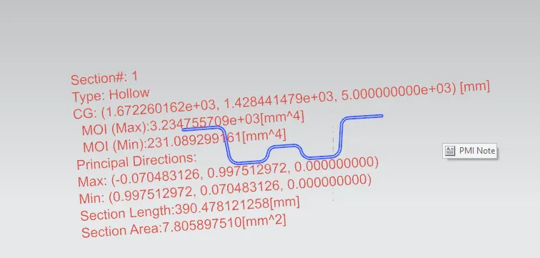
Centre bow roof-
| SNOW LOAD CALCULATION | ||||||||||||
| SR NO. | BOWS | Iy | α | Lx | Ly | Y | s | Rx | Ry | T | Qr | determination(Qr) |
| 1 | FR TO BR1 | 231.1 | 1.0 | 1116.401 | 2033.7 | 535.2 | 446.1476 | 4445.762 | 2673.2 | 0.75 | 2.300795 | NG |
| 2 | BR1 TO CR | 231.1 | 1.1 | 1053.749 | 2033.7 | 960.3 | 463.09 | 3579.002 | 5966.0 | 0.75 | 1.076773 | NG |
| 2 | CR1 TO BR2 | 231.1 | 0.9 | 1053.79 | 2033.7 | 1457.1 | 519.59 | 4216.184 | 10370.4 | 0.75 | 0.504117 | NG |
Now since we these values for the snow load values it does not satisfy the condition.
So to make the roof stronger we create embossses on the roof to strengthen the roof.
Draft analysis-
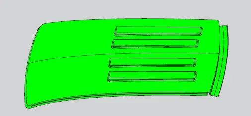
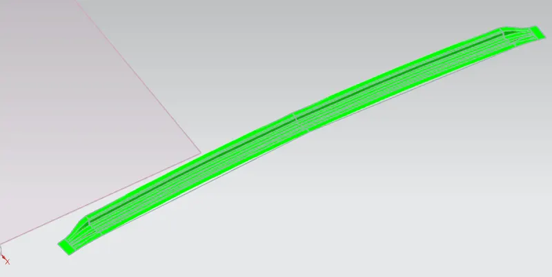
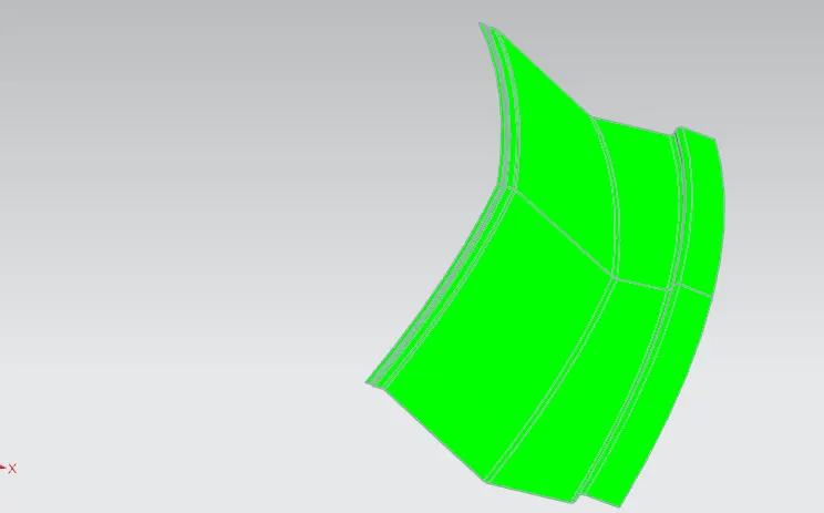
Before we give the part for manufacturing we have to some analysis ourself to check all the constraints and to check if we have any negative draft on a part .
We have a tool called draft analysis in NX Cad to check the following.
Roof-
Front roof rail-
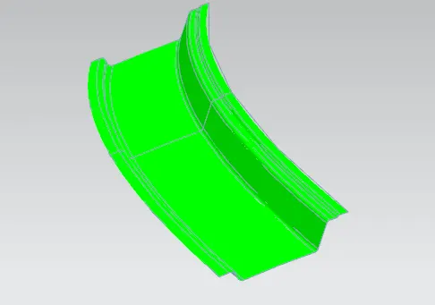
Bow roof 1-
Rear roof rail-
CONCLUSION
We were successfully able to design the roof with all the roof rails for better support and strength. We designed it so as to satisfy the norms and regulations by calculating the heat distortion criteria and the snow load critera. While doing this we also understood about the methodology behind designing the roof of the car and what all we take into consideration while designing so.