Roof Design
ROOF DESIGN
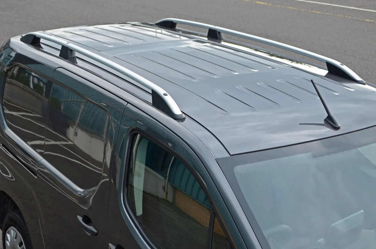
OBJECTIVE :
- The Objective of this project is to design car roof with essential flanges and reinforcement and perform the calculations for the Heat distortion and snow load criteria to determine the bow roof are at the correct position.
- Then finding moment of inertia and section modulus for front, bow, centre and rear roof rail and also perform the draft analysis for each reinforcements.
SOFTWARE USED FOR THE DESIGN is SIEMENS NX CAD.
INTRODUCTION :
- The roof of the vehicle is commonly referred t as the ROOF or the TOP OF THE VEHICLE. It's the uppermost part of the vehicle that provides protection from the elements and houses features like the sunroof or roof rake.
- Roof is not a single element, it consists of Front roof rail, Rear roof rail, Bow roof rail, Center roof rail. These bow roofs are placed in the most flat area of the Panel. Rear roof rail joins with the back door and body side outer. Front roof rail joins with the wind shield glass and body side.
- Roof is the structure above the wind shield glass having the reinforcements to provide the strength to the overall structure.
- Roof is protect by the different condition of the environment like snow or heat etc.
DESIGN PARAMETERS :
The design of the car roof is given by the design department as per requirements and then develop it & commonly the car roof consists of outer panel and its reinforcements. Those reinforcements are :
- Roof outer panel
- Front Roof Rail
- Bow Roof Rail
- Centre Roof Rail
- Rear roof Rail
ROOF OUTER PANEL :
The roof outer panel is the section of material, usually sheet metal, that forms the roof of a vehicle. The roof is split into three sections i.e., the aluminum roof panel, the strengthened C pillars and the rear windshield. The outer panel is also known as the external part which covers the occupant or passenger compartment from the windshield to the back door.
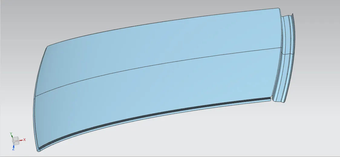
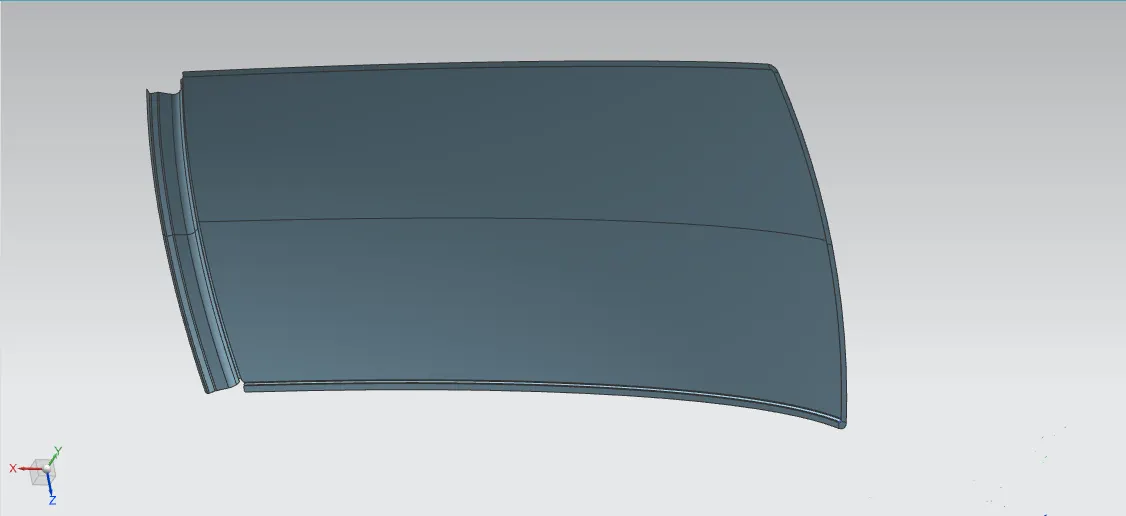
FRONT ROOF RAIL :
Front roof rail is one of the reinforcement of roof which joins the wind shield glass, body side inner and outer panel and it also provide Headroom clearance and visibility for the driver for good driving or it should be depends upon the front roof rail dimensions, hence it is important to select appropriate dimensions for the roof.
The Front roof rail master section and its dimensions for build perfect roof rail.
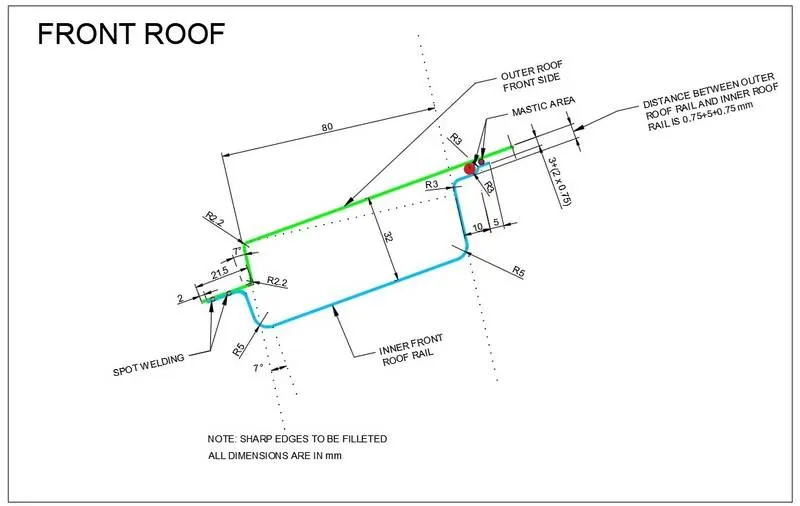
In the above master section we can draw the Front roof rail with the perfect dimension that shown in the Isometric view :--->
BOW ROOF RAIL ( 1 & 2 ) :
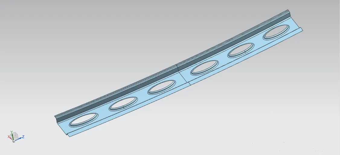
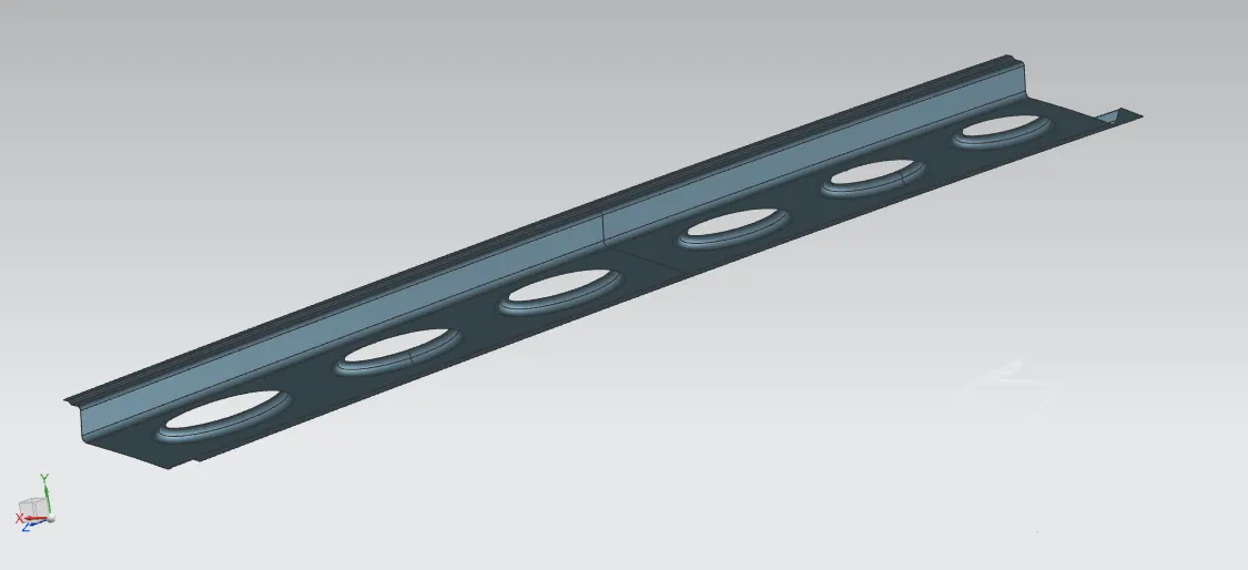
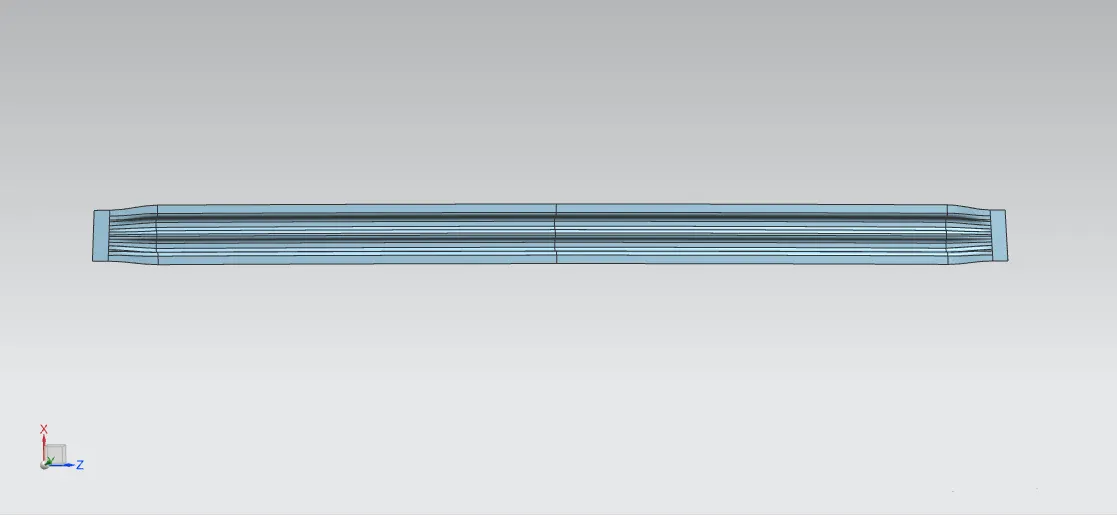
The two bow roofs are present in this design. The bow roofs are give to improve the torsional stiffness and load bearing capacity of the roof structure. The number of bow roof present is depends on the overall size of the roof. By using the bow roofs permanent deformation of roof at the flatter region is avoided by stress distribution.
The Bow roof rail master section and its dimensions for build perfect roof rail.
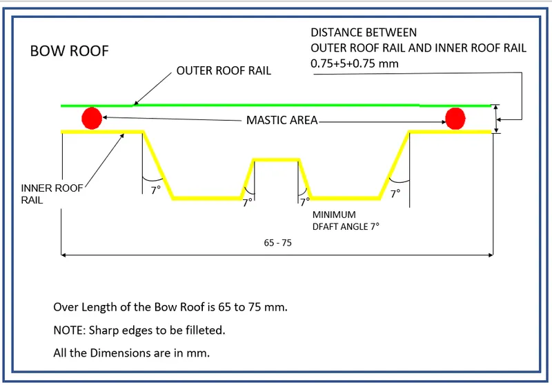
In the above master section we can draw the both Bow roof rail with the perfect dimension that shown in the Isometric view :--->
BOW ROOF RAIL 1 :
BOW ROOF RAIL 2 :
CENTRE ROOF RAIL :
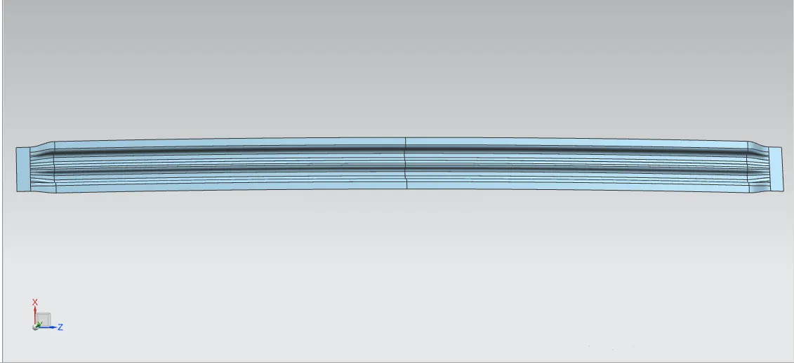
Centre roof rail help in providing effectively support to the flat area of the roof as it is more susceptible to failure under the action of load generally central roof rail is placed at the centre of the roof which is connected to the B piller support structure. The centre roof rail helps in adding the strength to the roof during the rool over test.
The Centre roof rail master section and its dimensions for build perfect roof rail.
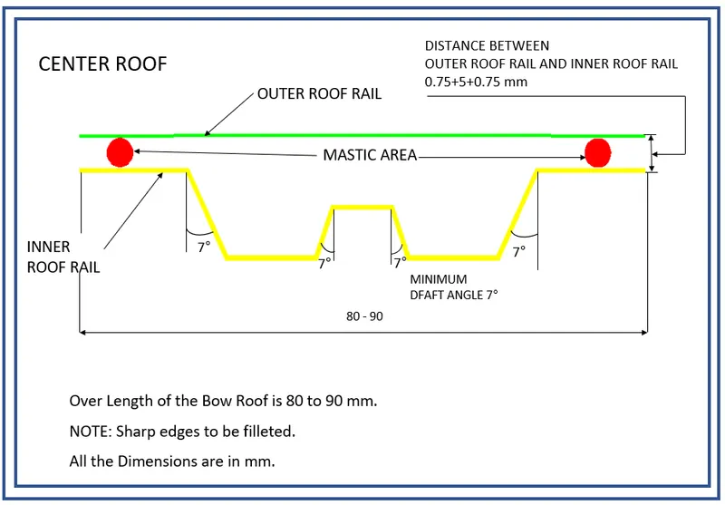
In the above master section we can draw the Centre roof rail with the perfect dimension that shown in the Isometric view :--->
REAR ROOF RAIL :
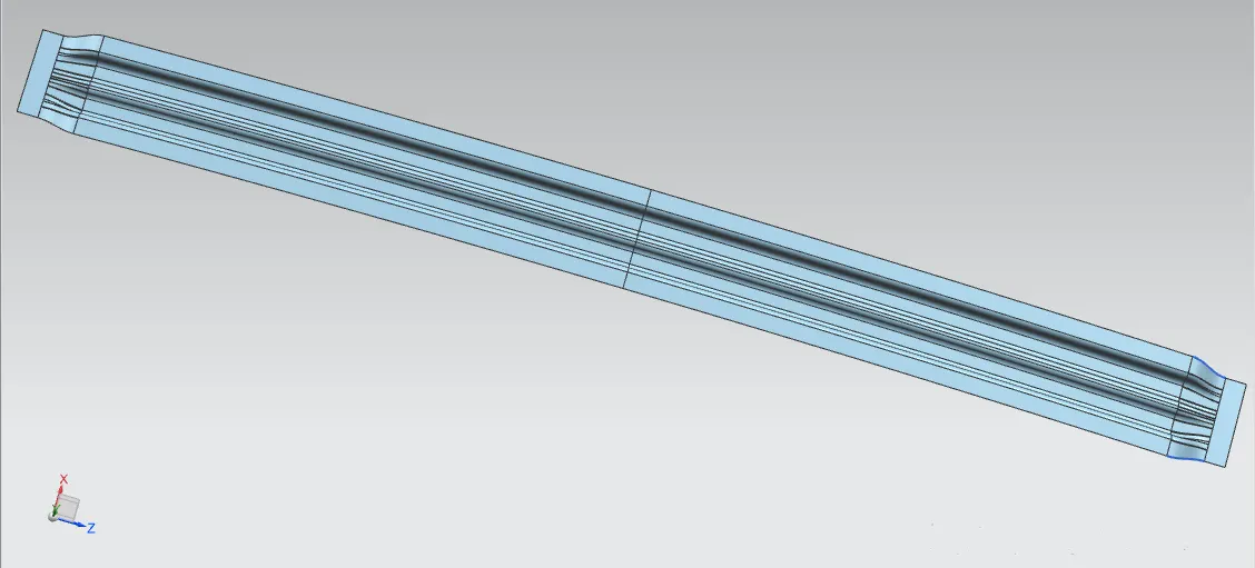
Rear roof rail is one of the reinforcement of the roof which joins the back door, rear wind shield or upper body panel.
The Rear roof rail master section and its dimensions for build perfect roof rail.
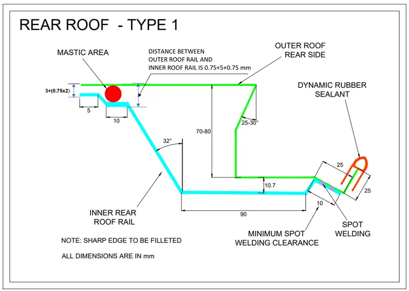
In the above master section we can draw the Rear roof rail with the perfect dimension that shown in the Isometric view :--->
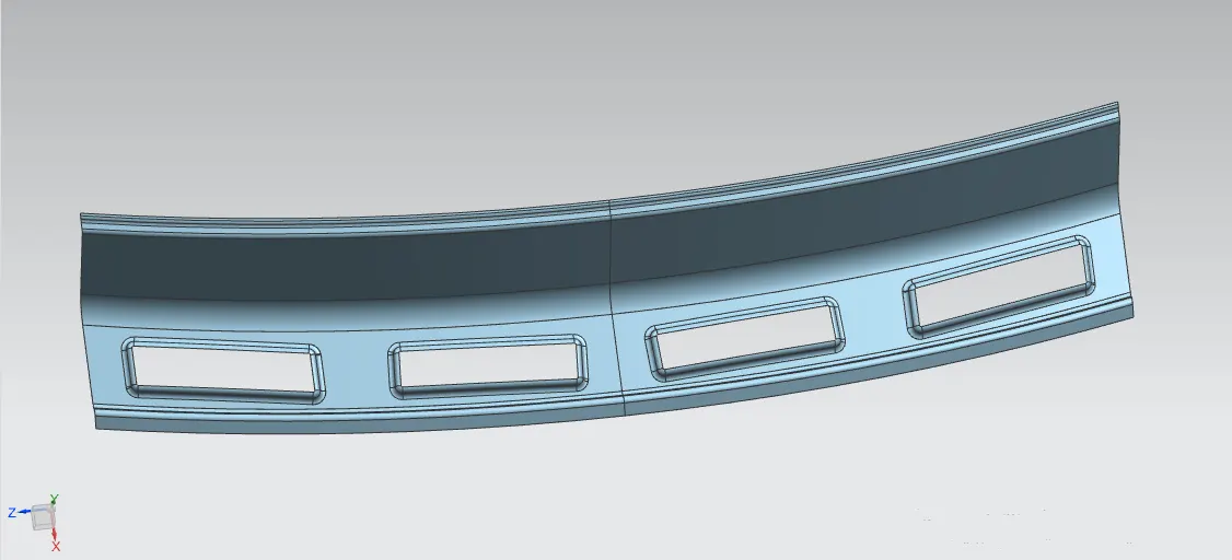
Assembled all reinforcement in the roof panel :
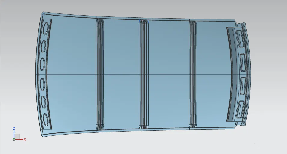
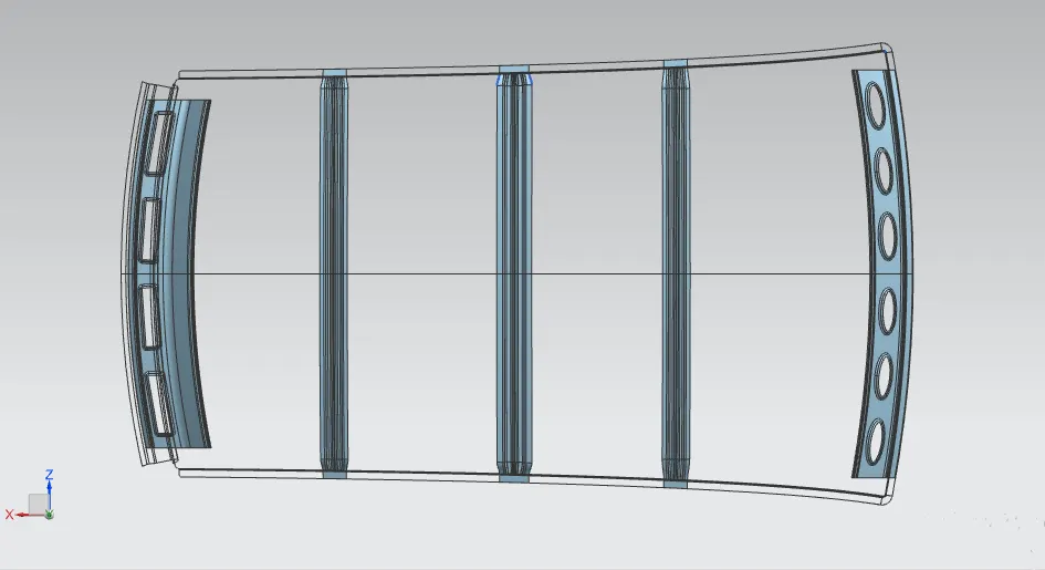
Mastics are introduced between the roof outer panel and reinforcements for joining. Spot welding is also introduced to join the reiforcement and the outer panel.
DESIGN ANALYSIS FOR ROOF :
- HEAT DISTORTION CRITERIA
- SNOW LOAD CRITERIA
- DRAFT ANALYSIS
HEAT DISTORTION CRITERIA :
Heat distortion criteria are used to determine the temperature at which materials begin to soften or deform when subjected to a specific load under elevated temperatures. In order to avoid bending or damages on the roof, based on the heat distortion temperature, this study will predict the positioning of the reinforcement which contributes to increase the strength.
BOW- ROOF PREDICTION FORMULA :
W = [1.73 x 10^(-3) x L] + [1.85 x 10^(-8) x (R^2)/t] + [ 1.10x10^(-3) x l] - 2.68
Where,
L = Roof Length in X-Direction [mm] (Roof dimension in 0-Y)
R = Roof curvature { R = 2(Rx*Ry)/(Rx+Ry) }
Rx = X curvature
Ry = Y curvature
t = Roof plate thickness [mm]
l = Bow Roof Span [mm]
Judgment Condition
OK< 2.7 > 3.1
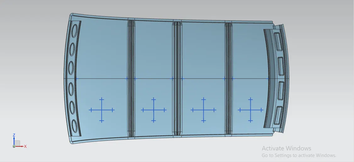
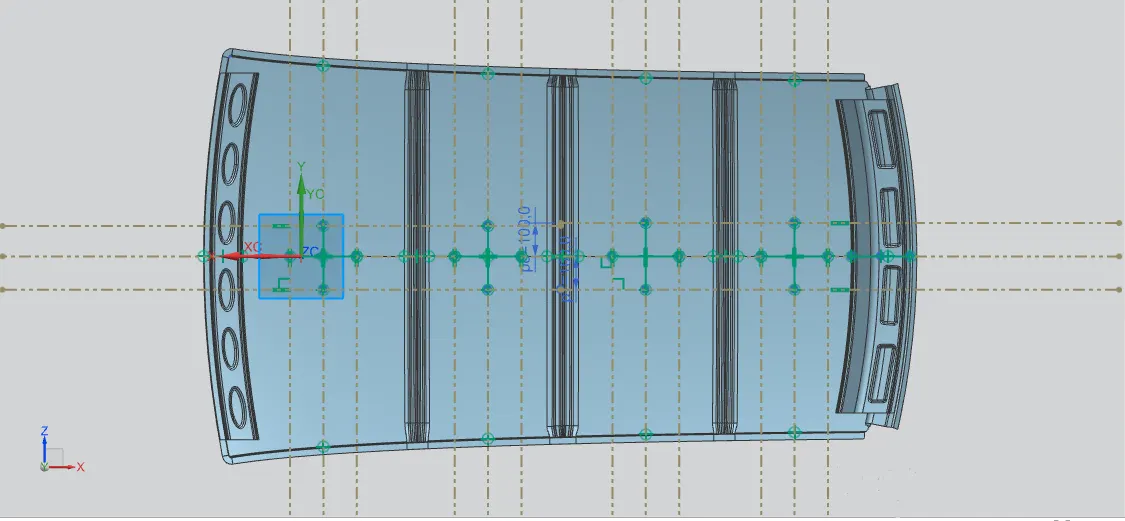
The above formula we can calculate or perform the heat distortion process because all the reinforcement are install at the correct places. Firstly we go on the nx cad model then select the plane you can draw the sketch. Select the sketch option and draw the line axis on (-3y , 3y) then draw the line at the gap of 100mm on both the side (we can say X-axis or Y-axis). After that measure the X-axis line and Y-axis for find the value of radius by this method. Let see the design of this method :-
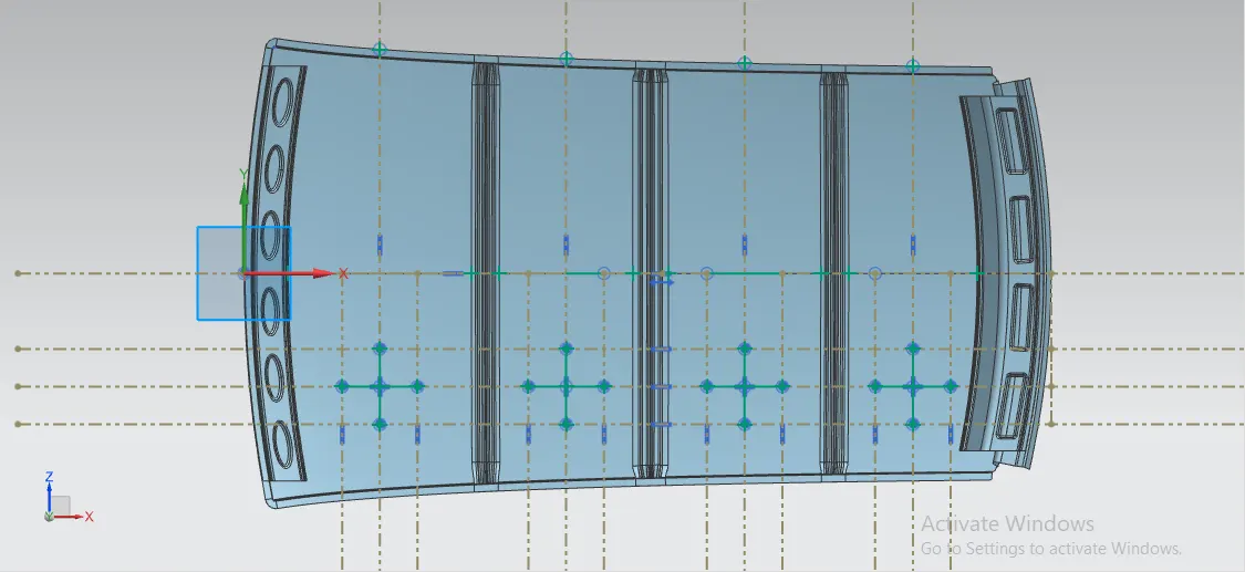
In above digram all lines are draw in 2D wireframe for mesurement all dimension.
In the above digram there is two curves is shown i.e., X-axis curve and Y-axis curve. After that measure all the values and put in the given formula for Judgment condition.
FINAL RESULT OF HEAT DISTORTION CRITERIA :

From the above table it can be calculate all the values of W<2.7 and also W>3.1. So, all the bow roof rails are in correct position as per design and judgment is OK.
SNOW LOAD CRITERIA :
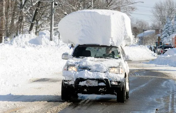
Snow load criteria test is done to know how is the roof behaving when there is a snow over the roof surface. Basically by the snow load the dent will happen over the roof but the roof should be designed in such a way that the snow load is removal the roof is coming to its original position. The snow load calculate by following formula :-
SNOW LOAD PREDICTION FORMULA :
Qr = [Iy x t2] / [α x s x [(Rx + Ry)/2]2 x 10-8]
Where,
[α = My x Lx2 x 10-12 , My = Y(Ly-Y) ]
t = Roof plate thickness [mm]
Ly = Distance between the front and rear roof Rails on the Vehicle along with 0Y[mm]. Length of Roof panel with the center point between Roof rail Front /Rear as the front and rear reference point.
Lx = Distance between the Left and Right end of the roof on the Roof BOW [mm]. The width of the roof panel is exposed on the surface.
Y = Distance front Front Roof Rail to Roof BOW[mm]
s = Distance for which Roof BOW bears divided load [mm]
( s = L1/2 + L2/2 )
Iy = Geometrical moment of inertia of Roof BOW (Y cross-section )[mm4]
Rx = Lateral direction curvature radius of roof panel Y cross-section on Roof BOW [mm]. Roof panel curvature Radius of the Length Lx in Front view
Ry = Longitudinal Direction curvature radius of the Roof panel X cross-section on Roof BOW [mm]. Roof panel X curvature radius of length s in Side view
Judgment condition
=> Qr ≥ 3.1 => 250 ≤ s ≤ 380
The above formula we can calculate or perform the snow load criteria because we can check all the reinforcement are able to take loads.
MOMENT OF INERTIA :
BOW ROOF 1 (FRONT) :
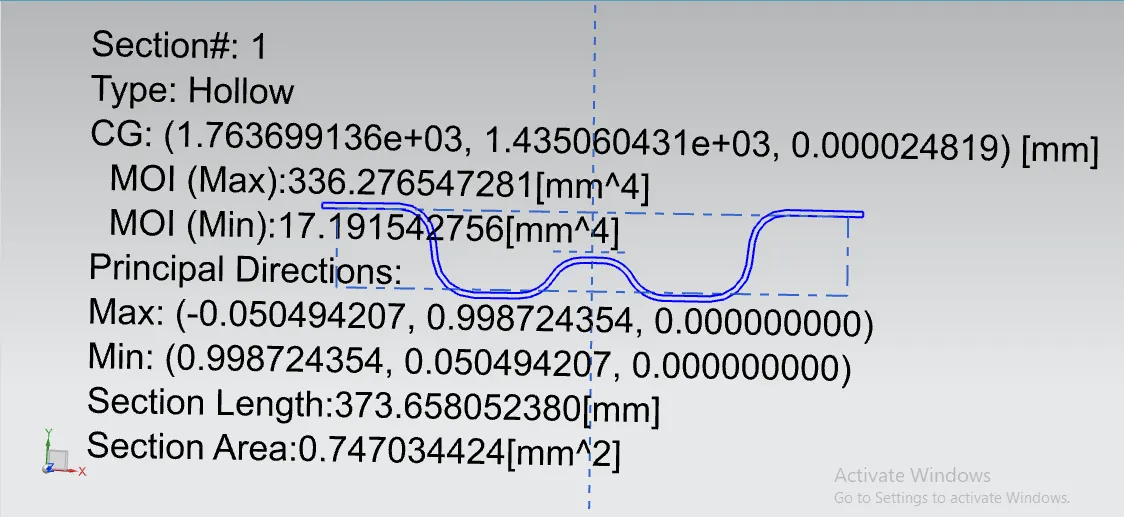
Therefore, we take Minimum moment of inertia (Bow roof 1) value is ly = 1719.15mm^4.
BOW ROOF 2 (REAR) :
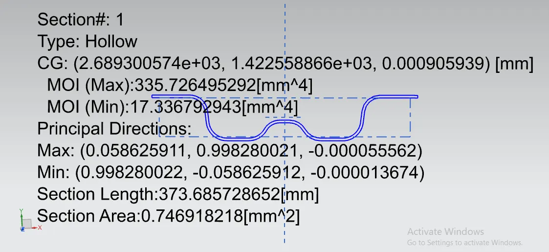
Take the Minimum moment of inertia (Bow roof 2) value is ly = 1733.67mm^4.
CENTRE ROOF RAIL :
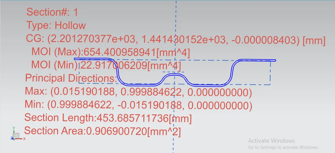
Take the Minimum moment of inertia (Center roof rail) value is ly = 2291.70mm^4.
FINAL RESULT OF SNOW LOAD CRITERIA :
We have the necessary values for finding the Snow load value (W) :=>

If the roof structure pass to the snow load condition then must have Qr values from above 3.1. (Qr ≥ 3.1)
DRAFT ANALYSIS :
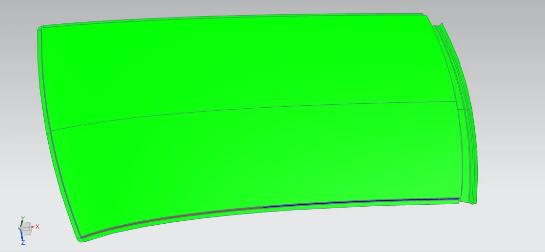
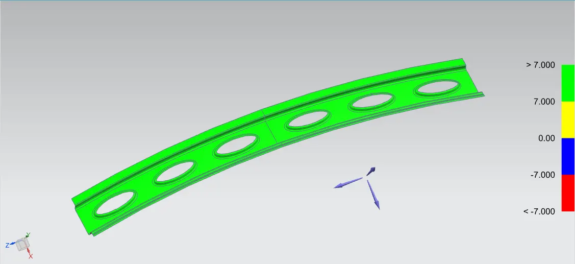
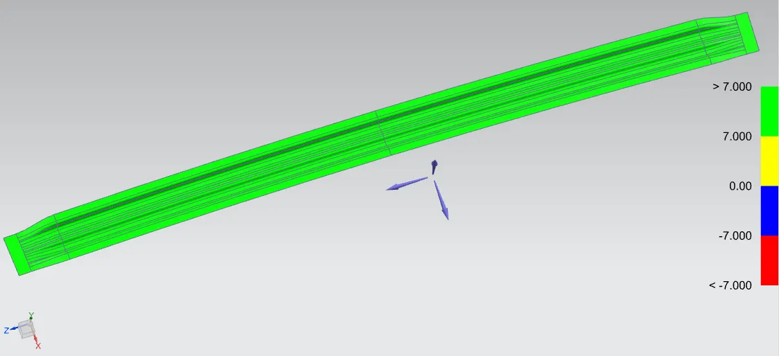
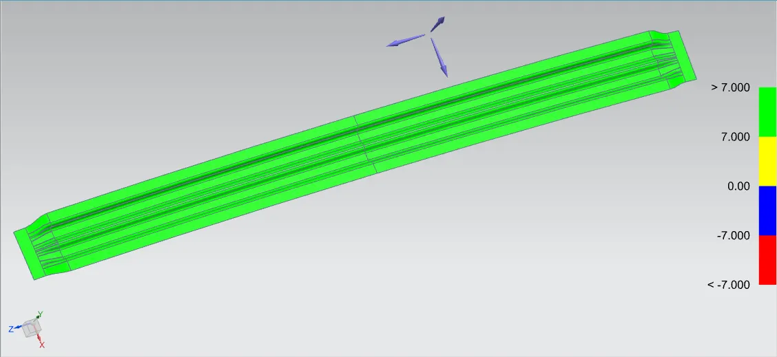
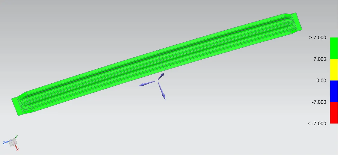
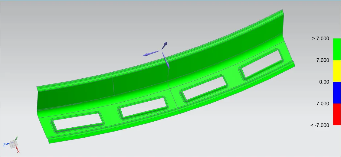
The Draft analysis command enable you to detect the part is coming under the design consideration. This type of analysis is performed based on colour ranges identifying zones on the analysed element where the deviation from the draft direction at any point corresponds to specified values.
Minimum draft angle is 7° is considered for analysis. Green colour show positive draft angle of the part more than 7°.
ROOF OUTER PANEL :
FRONT ROOF RAIL :
BOW ROOF RAIL 1 :
CENTRE ROOF RAIL :
BOW ROOF RAIL 2 :
REAR ROOF RAIL :
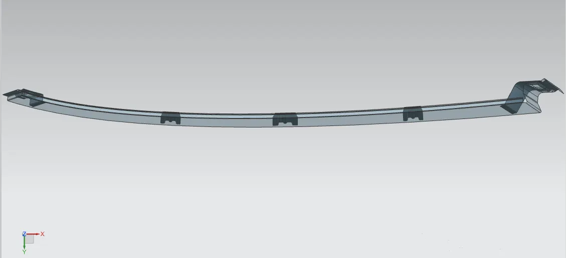
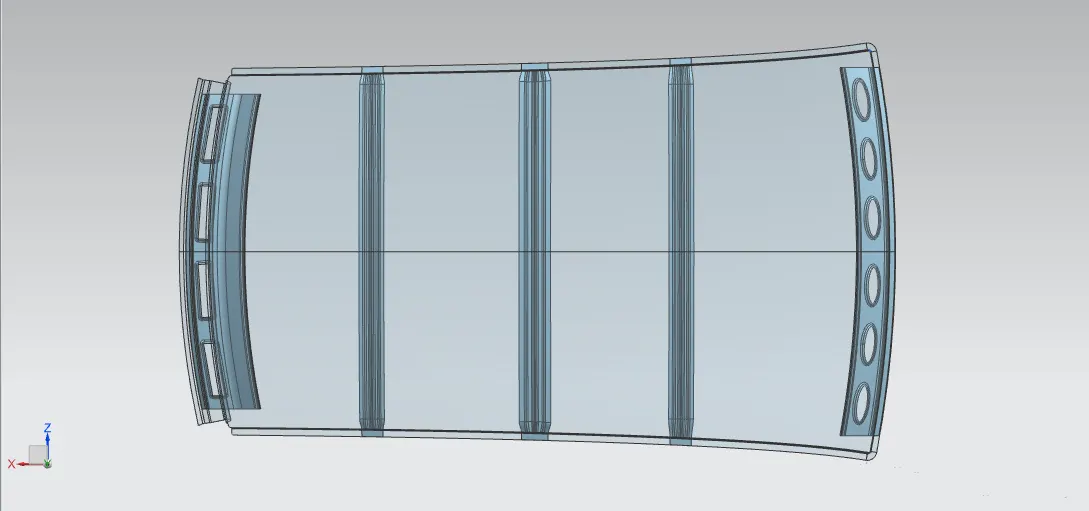
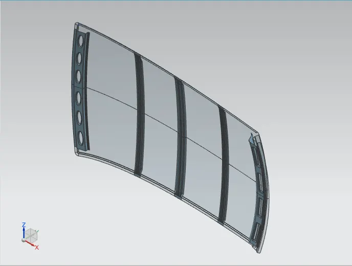
ROOF DESIGN VIEWS :-
FRONT VIEW :
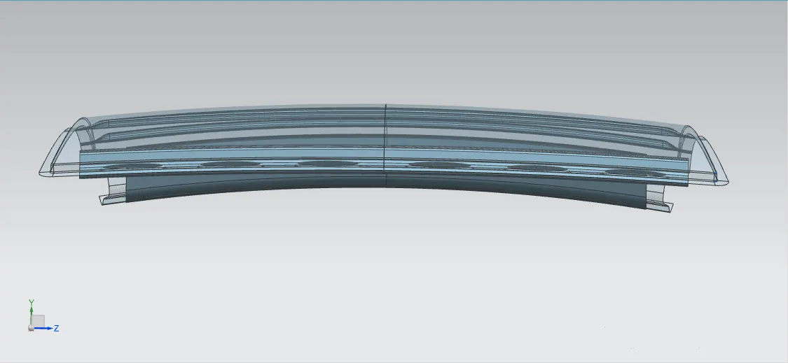
RIGHT VIEW :
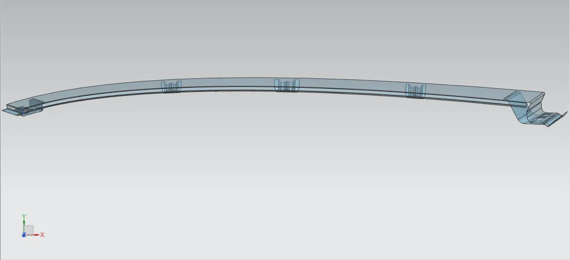
BACK VIEW :
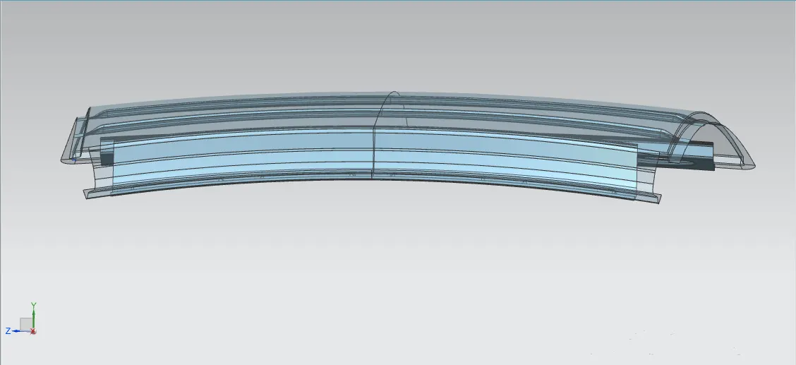
LEFT VIEW :
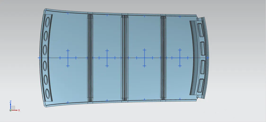
TOP VIEW :
ISOMETRIC VIEW :
CONCLUSION :
I did the roof design as per dimensions after that I complete my design then I go for check that all the bow's are placed at right position or not. So, I check the two criteria i.e., ( heat distortion and snow load condition). After finishing the curvature study then also check the draft analysis because, our part is manufacturable or not.
That's why I doing these types of analysis. So, my design passes all the requirements and ready to install the roof on the car.