Roof Design
Roof Design
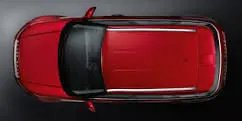
An automobile roof or car top is the portion of an automobile that sits above the passenger compartment, protecting the vehicle occupants from sun, wind, rain, and other external elements. Because the earliest automobiles were designed in an era of horse-drawn carriages, early automobile roofs used similar materials and designs.
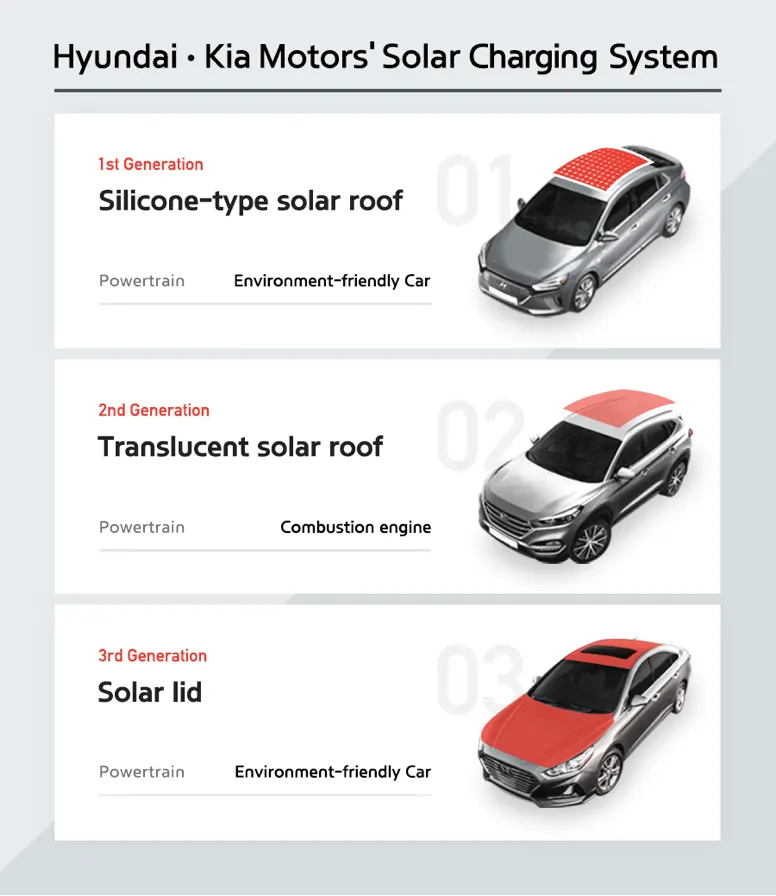
The Solar Charging System is not intended as a main, but as an auxiliary power source. It works to recharge batteries in motor-powered cars or support power generated by a combustion engine. Hyundai Motor Company is developing three separate solar charging systems; 1st gen. silicone-type solar roof, 2nd gen. translucent solar roof, and 3rd (next) gen. lightweight solar lid. First gen solar roof is a crystalline silicone photovoltaic cell panel attached on a standard roof. Second gen solar roof is designed for combustion-engine vehicles. For greater openness, it comes with the option of translucent design or open-close design. When solar charging systems augmented to a combustion engine vehicle expanded in volume, carbon credits may be awarded significantly towards the cost of observing environmental laws.
Third gen of this technology is a lightweight solar lid undergoing advance research for eco-friendly models. In this model, the solar cells are integrated directly into the car’s lid (e.g. bonnet) and the roof for maximum power output.
How a Solar Charging System workThe Solar Charging System’s components are the solar panel, controller, and battery.The Solar Charging System is composed of the solar panel, controller, and battery. When sunlight enters the cell surface of a solar panel, it is separated electrons and electron holes, creating energy. In the case of a 100 W class solar panel attached, 1Sun unit (summertime midday 1000 W/㎡ light quantity) generates 100 Watts of power. In summary, 1 hour of sunlight can generate 100 Watt-hours of stored energy.
Reinforcements and Design
Roof design
ASSEMBLY DETAILS
Analysis
- Curvature Study
It is done to justify the positioning of the Bow Roofs. There are mainly three criterion to fulfill
- Roof Crush test
- Heat Distortion Criteria
- Snow Load Criteria
Roof Crush Testing is done only after the part or prototype is manufactured in physical conditions.
- Heat Distortion Criteria
Heat distortion temperature is the temperature at which the metal softens and deforms under a specific load. This study is done to check the ability of the roof to withstand high temperature with respect to the positioning of the reinforcements which contribute to increased strength.
Prediction Formula : W=1.73×10⁻³×L+1.85×10⁻⁸×R2t+1.10×10⁻³×l−2.68W=1.73×10⁻³×L+1.85×10⁻⁸×R2t+1.10×10⁻³×l-2.68
Judgement Condition: OK < 2.7mm ≤ NG
Where,
L = Roof Length in X-Direction [mm] (Roof dimension in 0-Y)
R = Roof curvature= 2(Rx*Ry) / (Rx+Ry)
Rx = X curvature
Ry = Y curvature
t = Roof plate thickness (mm)
l = Bow Roof Span (mm)
When applying the corresponding measurements into the formula, the criterion is met for all the reinforcements.
Table 1- Heat Distortion criterion calculation
- Snow Load Criteria
Snow load criteria study is done to check the ability of the roof to withstand snowfall and bounce back to its original shape without any permanent deformation once the load is removed.
Prediction Formula: Qr=Iy×t2α×s×(Rx+Ry2)2×10⁻⁸Qr=Iy×t2α×s×(Rx+Ry2)2×10⁻⁸
Judgment condition: Qr ≥ 3.1
Where,
α=My×Lx2×10−12,My=Y(Ly−Y)α=My×Lx2×10-12,My=Y(Ly-Y)
t = Roof plate thickness (mm)
Ly = Distance between front and rear roof rails on vehicle 0-Y (mm) i.e. Length of Roof panel with the centre point between Roof rail FR/RR as the reference point of the front/rear.
Lx = Distance between the left and right end of roof on the roof BOW (mm) i.e. Width of the Roof panel exposed on surface
Y = Distance from Front roof rail centre to Bow roof (mm)
s = Distance for which Bow roof bears divided load (mm) = L1/L2 + L2/2
Iy = Geometrical moment of inertia of Bow roof (Y cross section) (mm4)
Rx = Lateral direction curvature radius of roof panel Y cross section on Bow roof (mm) i.e. Roof panel curvature radius of the length Lx in front view
Ry = Longitudinal direction of curvature radius of roof panel X cross section on Bow roof (mm) i.e. Roof panel X curvature radius of the length s in side view
When applying the corresponding measurements into the formula, the criterion is met for all the reinforcements.
- Section Modulus Study
Section modulus is a geometric property for a given cross-section used in the design of beams or flexural members. There are two types of section moduli, the Elastic Section Modulus and the Plastic Section Modulus. For general design, the Elastic Section Modulus is used, applying up to the Yield Point for most metals and other common materials.
Section modulus is calculated using the formula
S=IyS=Iy
Where,
S = Section Modulus
I = Moment of Inertia
Y = distance between the neutral axis and the extreme end of the object
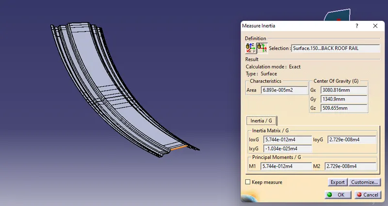
Front Roof Rail
I = 5,744e-008 m4 = 20050 mm4
Y = 99.5 mm
S = 574.40 mm3
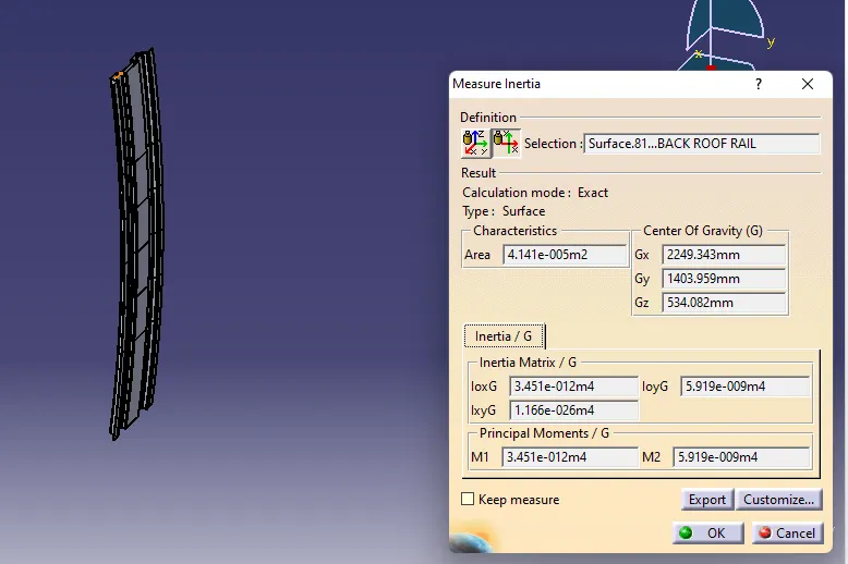
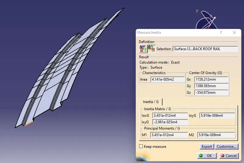
Centre Roof Rail
I = 3.451e-008 m4 = 20050 mm4
Y = 99.5 mm
S = 345.10 mm3
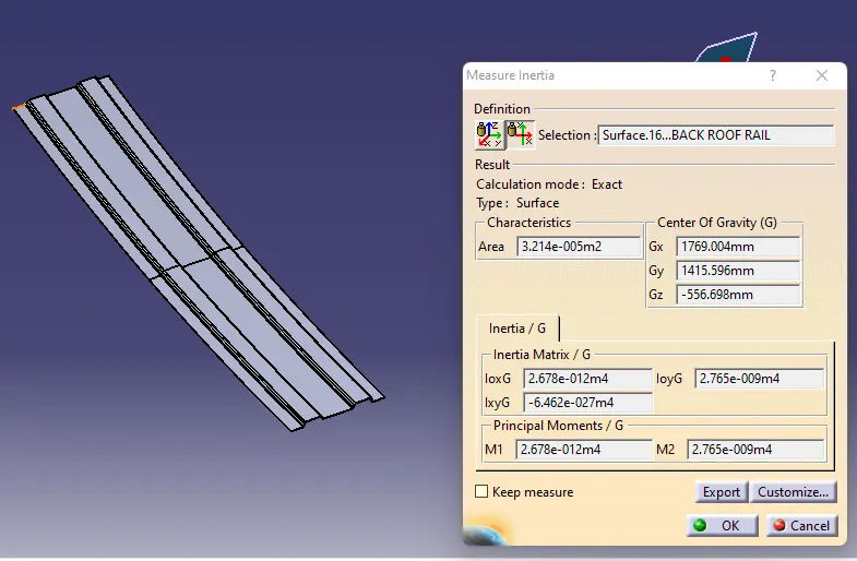
REAR Roof Rail
I = 2.678 e-008 m4 = 20050 mm4
Y = 99.5 mm
S = 267.8 mm3
BOW1 Roof Rail
I = 3.451 e-008 m4 = 20050 mm4
Y = 99.5 mm
S = 324.1 mm3
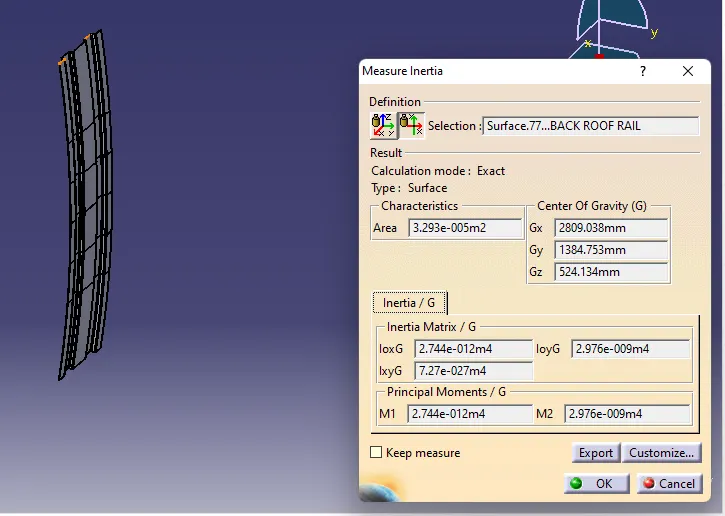
BOW 2 Roof Rail
I = 2.744 e-008 m4 = 20050 mm4
Y = 99.5 mm
S = 274.4 mm3
- Draft Analysis
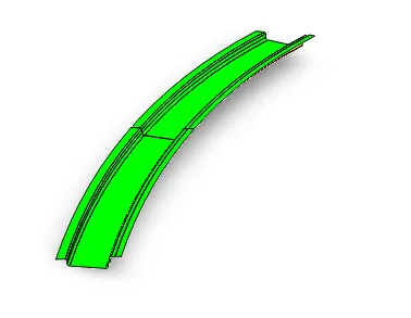
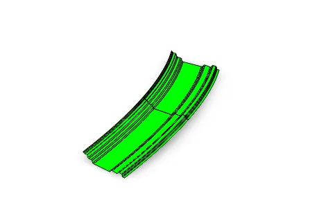
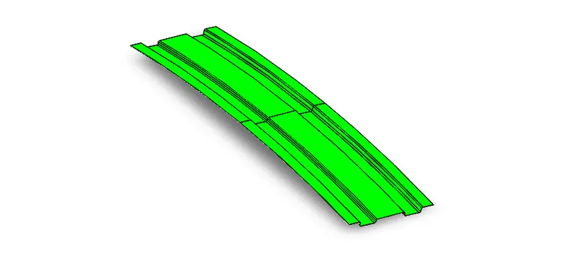
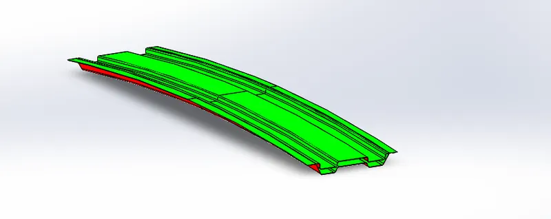
Draft Analysis is done to analyze the draft angle. This allows us to verify whether the product will be easily removed from the tool.
When designing a product they need to be angled slightly so that the tool can be pulled away from the object easily, without deformation or damage. This slight angle is called draft.
Front Roof Rail
Rear Roof Rail
Bow 1 Roof Rail
Centre Roof Rail
Bow 2 Roof Rail
I have given the condition for draft angle with a maximum deviation of 5 degrees. Anything within that limit is shown in green, which means that the part is producible.
Conclusion:
Designed & Develop the Essential Flanges and Reinforcements, and check for Draft analysis and also section modulus report on the 0-Y section.
The required reinforcements and Ditch Area for the Roof were designed and developed from the given styling. The curvature study was done after performing calculations for the Heat Distortion and Snow load conditions with the position criterion met for all reinforcements.
Further the Section Modulus study was conducted and Draft Analysis were done for each reinforcement succesfully.