Roof Crash Analysis Simulation on the BIW Component of the Neon Car Model.
AIM: Roof Crash Analysis Simulation on the BIW Component of the Neon Car Model.
OBJECTIVES:
Transforms:
• This will require (in order)
• A 180° rotation about the global z-axis with the point opposite to C as base point
• A 5° rotation about the axis through axis AB
• A 25° rotation about the axis through axis AC
• A translation to put point A at global ( -3500.00, 584.822, 1343.06)
Interfaces:
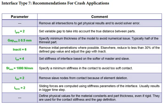
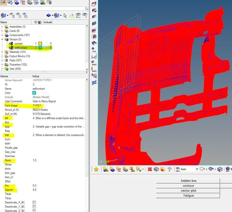
• Create a Type 7 contact interface between the impactor and the car
• choose an appropriate stiffness definition
• choose an appropriate minimum gap
• change the coefficient of friction to 0.2
• choose the appropriate friction penalty formulation
• Save the data from the interface to the time history file.
Boundary condition:
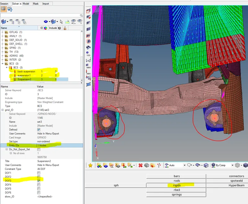
keep the suspension shock tower nodes locked in Z.
Impactor Boundary Conditions:
• The impactor assembly contains a spring attached for stability. Create a BCS
collector to fix the free end of the spring.
• Create a moving SKEW to define the direction normal to the impactor’s
face.
• Create a BCS collector to guide the master node of the impactor rigid body
so that it is free to translate normal to the face of the impactor, but is fixed
in all other DOFs.
Imposed Displacement:
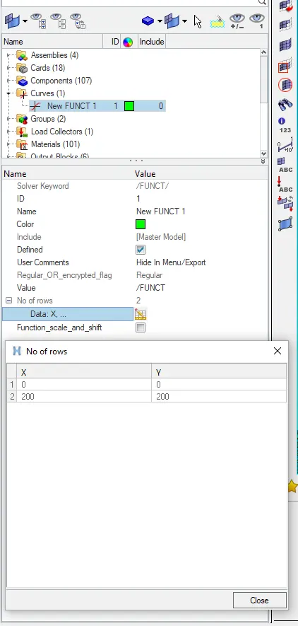
• Impose the velocity of the impactor starting from 0 mm/s at t = 0. The
displacement of the impactor should be 200 mm @ 200 ms.
• Avoid abrupt changes in the acceleration of the impactor.
Control Cards:
• /ANALY card
• /DEF_SHELL card,
• /DEF_SOLID card, and
• /IOFLAG card
• /SPMD card
• /TITLE card
Engine File:
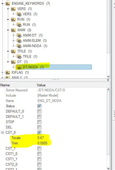
• Use a constant nodal time step
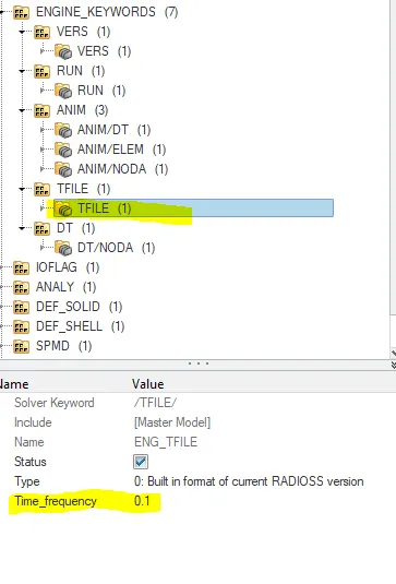
• Print time history every 0.0001 seconds
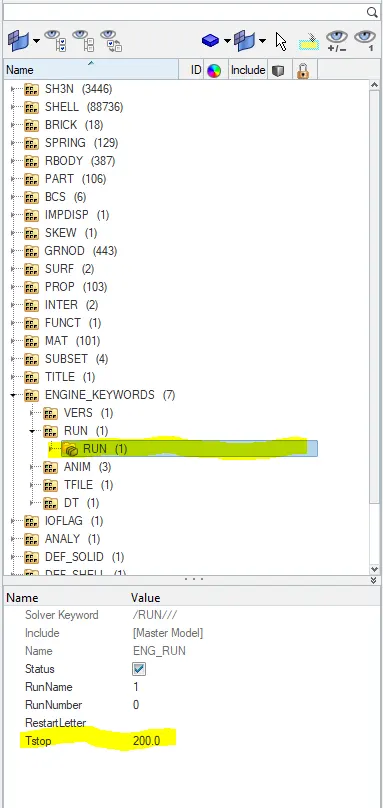
• Solve for 200 ms
• Create an animation file every 0.005 seconds
Include selected output in animation files:
• Elemental Energy
• Elemental equivalent plastic strain
• Elemental hourglass energy
• Elemental von Mises stress
• Nodal added mass
• Turn on parallel arithmetic
Solution and Results Post Processing:
• Run the model
• Plot force vs. displacement. Check that the FMVSS 216 target load of
47,000 N (= 3 * GVW) has been met.
• Plot the energy vs. time curves
PROCEDURE:
Transforms:
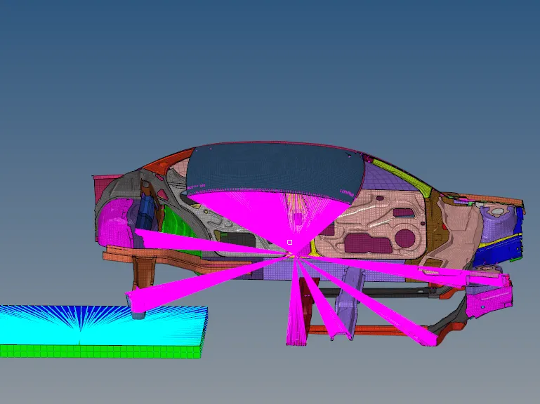
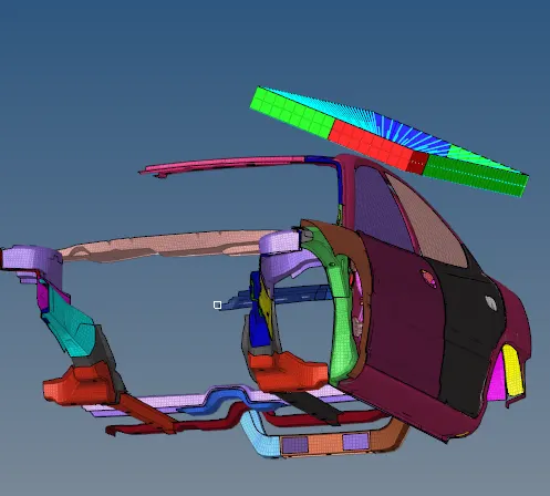
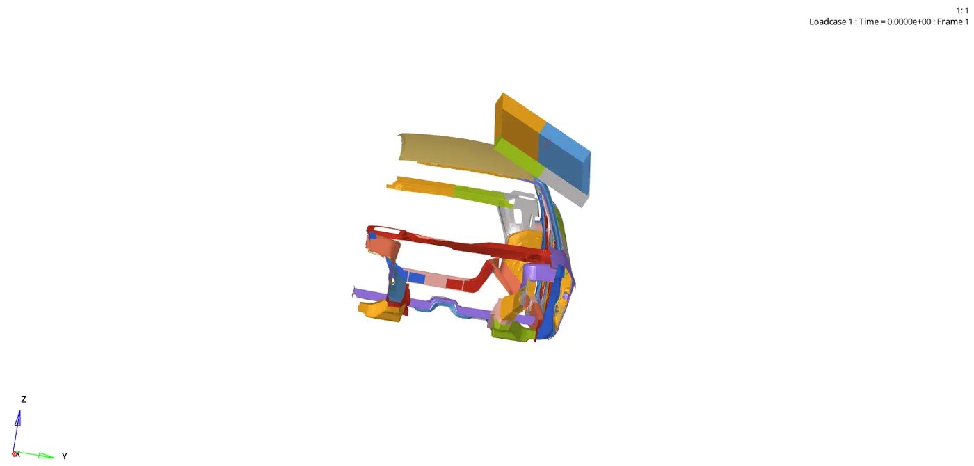
- Import the both car and impactor models then make sure that the impactor is in correct else place the impactor at the corrrect place.
- Use translate option to translate the impactor to the correct place as given in objectives.
- Then use the rotate option to rotate the impactor in required direction as shown in the below images.
- 180 deg about(Z-axis),5 deg about axis (AB) and 25 deg about axis(AC).
Interfaces:
Recommendations Parameters:
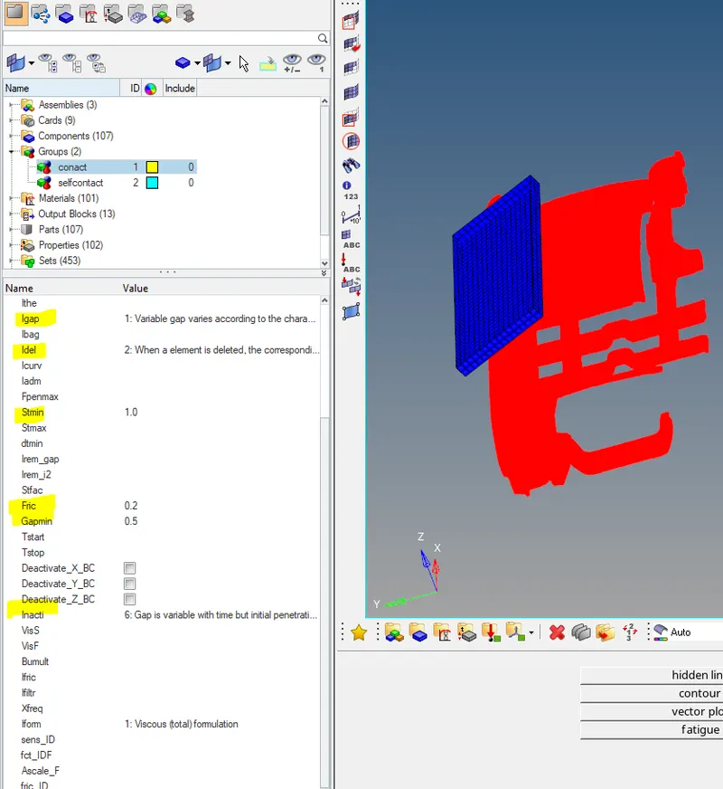
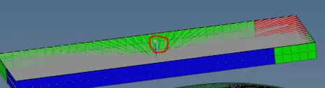
- Here we have to define the type7 contact and self contact for the model for that define the (Impactor as the Master) and Car model as the Slave.
- Then we have to define the self contact for the Car for that model give both master and slave on the same component as shown in the below images.
Boundary conditions:
- Here we have to keep the suspension shock absorber towards nodes locked in the Z-direction.
- Here we are having a three suspension shock aborber for we suppose to lock the z-direction for three components for that create the rigid bodies>then goto the slover >select the master node >make sure untick the DOF3 as shown in the below images.
Model checker(Fix the free flying components):
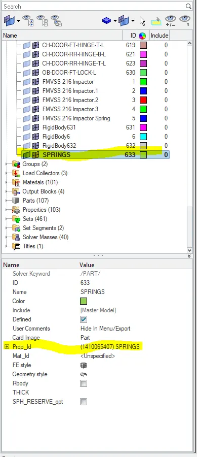
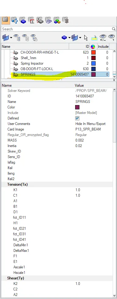
- To fix that issues goto the model checker >find conectivity>there we can see the free parts ,we can isolate them individualy and connect with spring elements or rigid bodies with the adjucent surfaces as shown in the below images.
- Make sure that all springs which we are creating are in current component and we sholud give the certain property ID to the springs which we are creating as shown in tye below images.
Impactor Boundary Conditions:
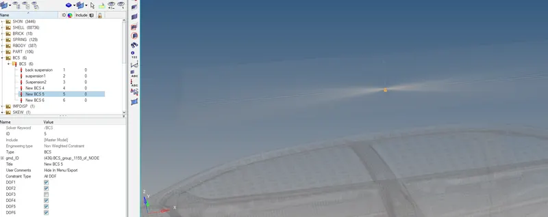
• The impactor assembly contains a spring attached for stability. Create a BCS collector to fix the free end of the spring as shown in below images.
• Create a moving SKEW to define the direction normal to the impactor’s face as shown in the below images.
• Create a BCS collector to guide the master node of the impactor rigid body so that it is free to translate normal to the face of the impactor, but is fixed in all other DOFs as shown in the below images.
Imposed Displacement:
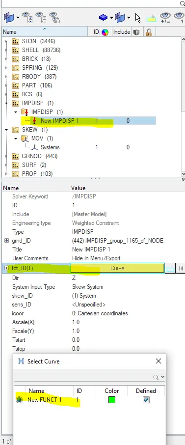
- Impose the velocity of the impactor starting from 0 mm/ms at t=0,the displacement of the impactor should be 200mm for 200ms.For that we have to create the displacement curve as shown in the below images.
- Avoid abrupt changes in the acceleration of the impactor.
About the Engine file:
- Use the constant nodel time step(0.0005ms)
- Print time history every(0.0001secs)
- Solve for the 200ms
- Create the animation file every 0.005secs

OUTPUT AND PLOT RESULTS:
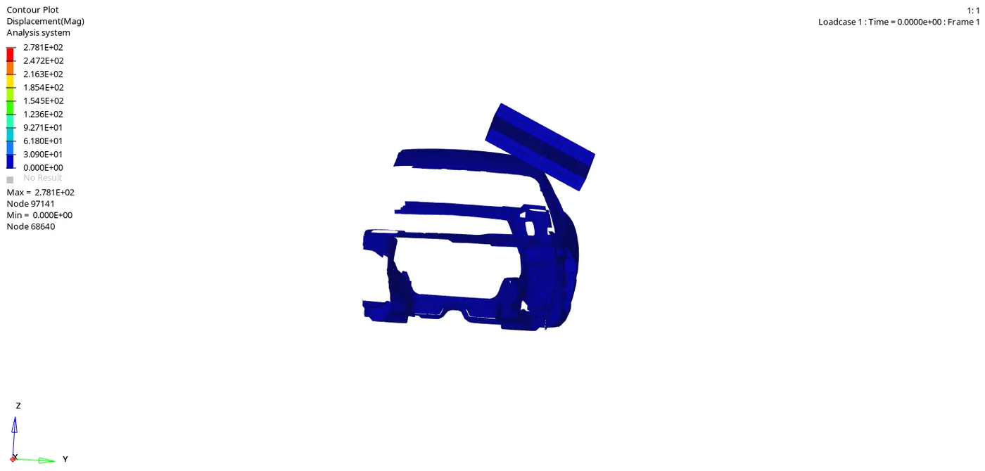
Animation:
Displacement:
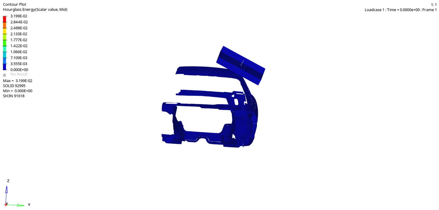
Hourglass Energy:
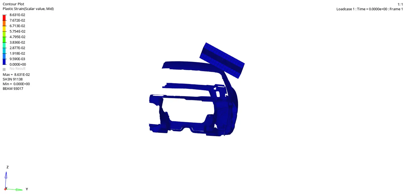
Plastic strain:
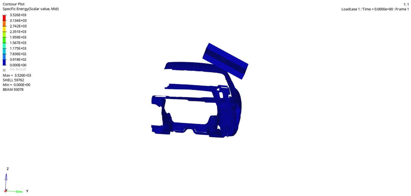
Specific Energy:
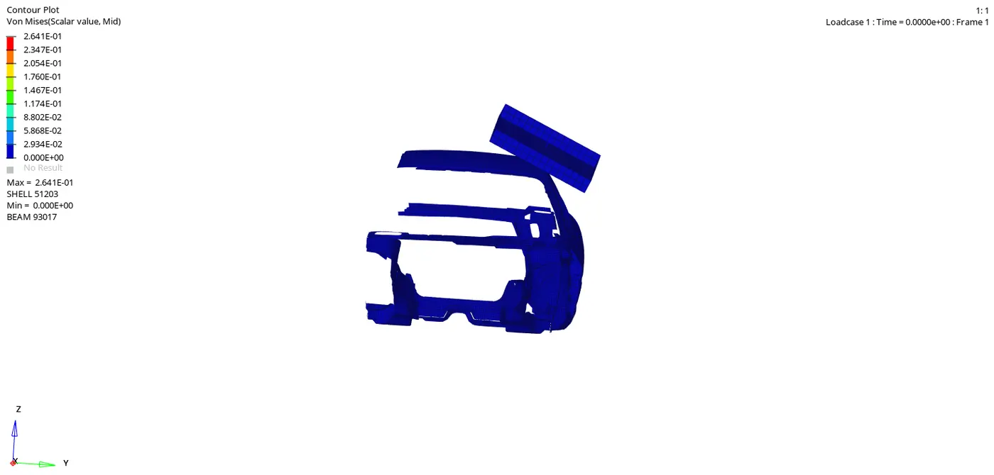
Vonmises Stress:
Plot Force vs Displacement:
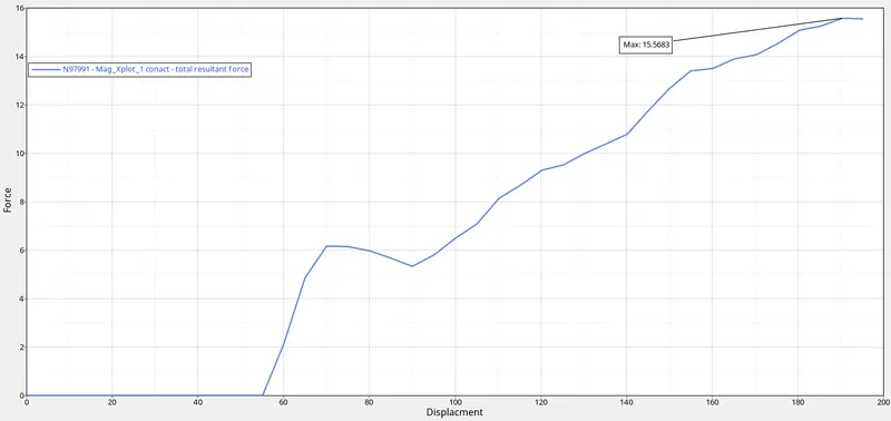
- Here the maximum force that Roof can resist from impactor is (15.56)KN as shown in the above graph.
- As per FMVSS 216 Specified strength to weight ratio (SWR)=3*GVW(gross vechile weight) after caluclation 4.7088KN value came .
- But our max force is 15.56KN >4.7088KN as shown in the above graph then that makes sence that our vechile is failing for the Roof crash analysis.
- Then there is huge difference between the target load and actual load so that our vechile is failing for the Roof crash analysis to approach to Target load.
ENERGIES:
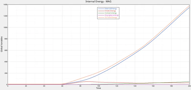
- Here hourglass energy is very less as we observe in the above graph and contact energy is increasing after impactor touchs the model .
- And kinetic energy is also slightly increasing and some what decrease after impact as we observe in the above graph.
- As we know after impact the internal energy and total energy is increasing as shown in the above graph.
CONCLUSION:
- As per FMVSS 216 Specified strength to weight ratio (SWR)=3*GVW(gross vechile weight) after caluclation 4.7088KN value came .
- But our max force is 15.56KN >4.7088KN as shown in the above graph then that makes sence that our vechile is failing for the Roof crash analysis.
- Then there is huge difference between the target load and actual load so that our vechile is failing for the Roof crash analysis to approach to Target load.