Roof challenge
OBJECTIVE :-
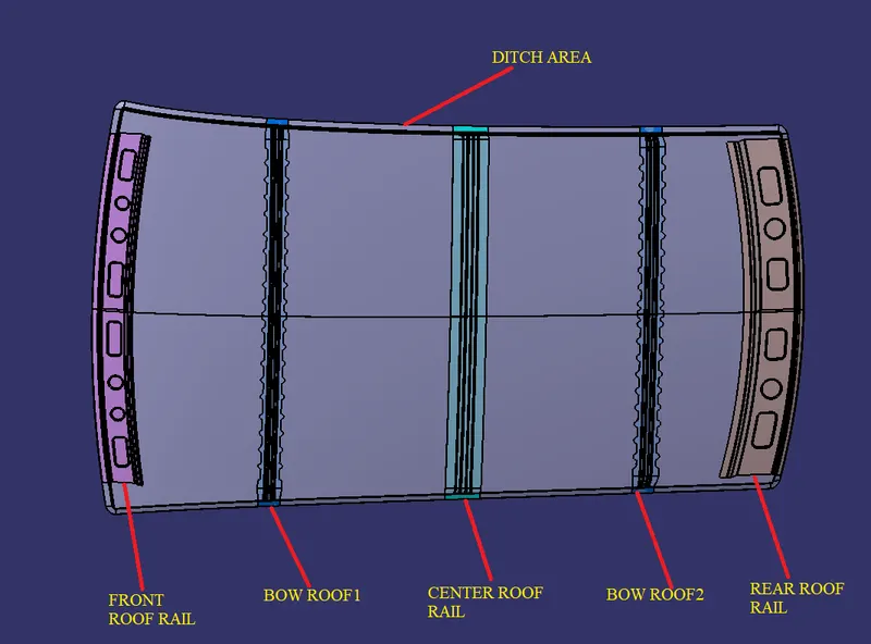
1. For the given Car Roof styling, design and develop the essential flanges and reinforcements, namely the Ditch Area, Front Roof Rail, Rear Roof Rail, Centre Roof Rail and Bow-Roofs.
2. Do a curvature study on the roof and perform calculations for Heat Distortion and Snow load criterion to determine and justify the position of the Bow-roofs.
3. Do a Section Modulus study for the Master sections created for the Front Roof Rail, Rear Roof Rail, Bow Roof Rails and Centre Roof Rail
4. Perform Draft Analysis of each reinforcement.
INTRODUCTION:-
WHAT IS CAR ROOF :-

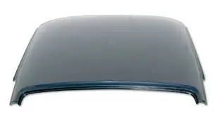
Roof of an automobile is that commodity which sits above the passenger compartment. Roof houses the vehicle as shielding part which safeguards the occupants from sunlight, heat, rain, wind, dust, etc.
In the past roof was introduced as cover for passenger compartment but later on, it also used as a luggage carrier, sunroof and in recent past years with the introduction of the solar panelled electric vehicle got a major boost in the automotive industry.
FUNCTIONS OF ROOF:-
- protects from external damage
- prevents passenger and vehicle from accidents
- luggage carrier
- design of the roof also affects in giving aerodynamic shape to vehicle
- sunroof
- solar panelled roof in EV
Since the roof has numerous functions so the roof has to be stronger enough to withstand the damage experienced by it. To have good strength and stiffness, the roof is made with different components such as front roof rail, rear roof rail, bow roofs, etc.
SOFTWARE USED :-
Catia V5
DESIGN CONSIDERATIONS :-
- Visibility criteria
- Head clearance
- Curvature study
- Heat Distortion and Snow load criteria
- Material thickness
MAIN COMPONENTS OF ROOF :-
1. Ditch area :-
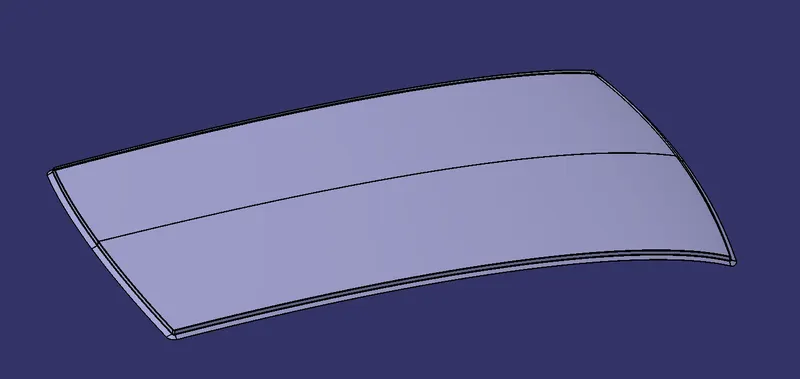
The Ditch Area is the extended portion of the main Roof concealed by other BiW panels. The rail supports of the roof are attached to the Ditch Area using Spot welds, since it is not a styling surface and remains concealed. Headroom Clearance, visibility criteria, clearance for Wind shield and Back door are some of the factors to be considered while designing the Ditch Area. It is given a thickness of 0.7 mm.
2. Front roof rail:-
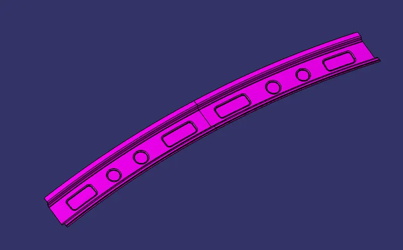
It is the support that is joined with the windshield glass, body side outer and inner panels. It is usually made from bodyside outer scrap and therefore the thickness of the rail is 0.75mm. A draft angle of 7-10 degree is provided for deep drawing operation. The visibility criteria and head room clearance of the passengers are taken into consideration for the bottom most flange. Windshield end and the roof end are spot welded and the other end of the front roof rail is joined with the roof using mastic sealants for increased strength.
3. Rear roof rail :-
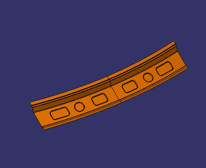
It is the support which is joined to the Back Door and the Body Side Outer and the inner panels. It is also usually made from Body Side Outer scrap and therefore the thickness of the rail is 0.65 mm. Similar to the Front Roof Rail design, we have to take into consideration the rear Headroom Clearance and the rear visibility criteria while designing the Rear Roof Rail. Inputs from the backdoor design is also taken to accommodate the required clearance. Spot Welds are applied at the Back doorend of the rail and the other end is joined with the roof using Mastic Sealants.
4.Center roof rail :-
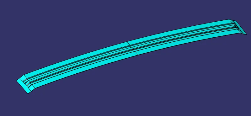
Center roof rail or reinforcement center is used as a cross member between bodyside left hand and right hand respectively. In some cases, the reinforcement center is not joined with the roof and in some other cases, it is made to join in both roof and bodyside. The reinforcement center and Bow roof are joined either spot weld or by mastic sealants.
5.Bow roof 1 :-
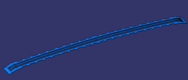
Bow roof center 1 is an additional stiffening member used in the roof assembly for the localised strength improvement and it is join directly to roof itself with several spot welding or even with mastic sealent.
No sharp corners:-
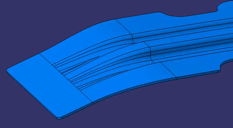
6. Bow roof 2 :-
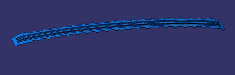
It is similar to that of bow roof 1 which serves the same purpose as the previous .
Assemly :-
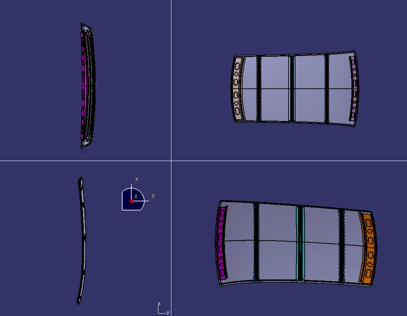
Part images :-
DESIGN PARAMTERS :-
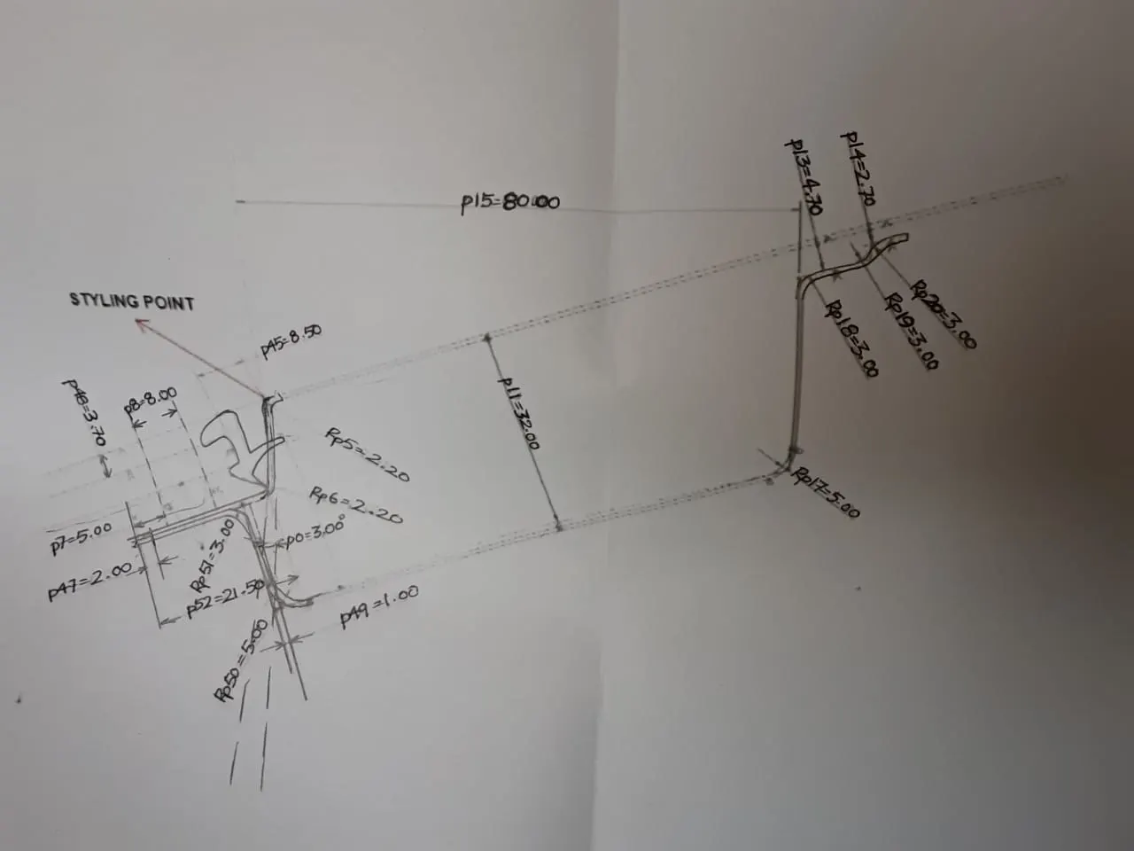
1. For Front roof rail :-
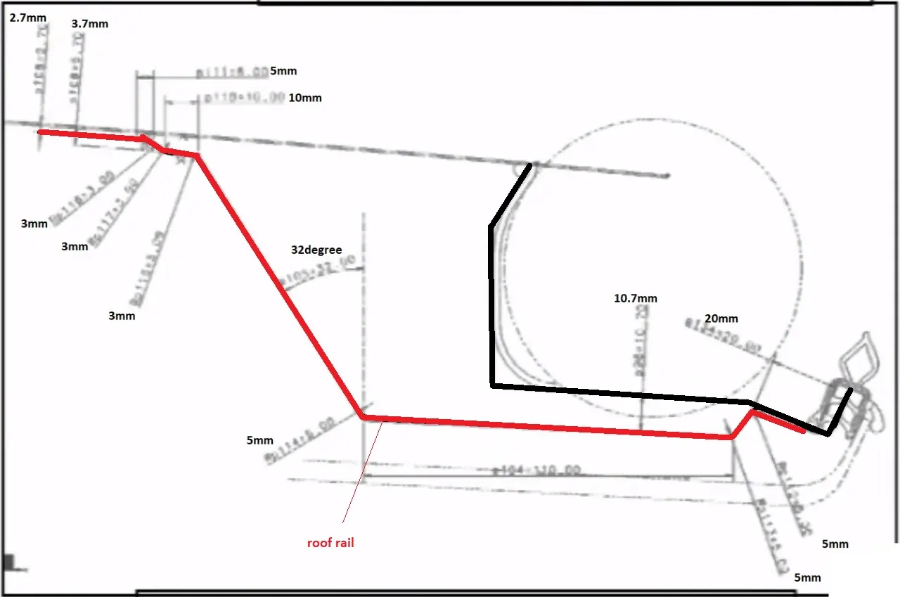
2. For rear roof rail :-
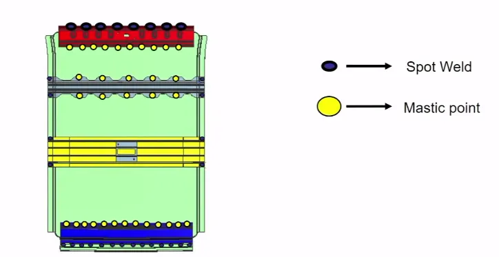
JOINING PROCESS :-
1.Spot welding :-
Spot welding (resistance spot welding) is a type of electric resistance welding used to weld various sheet metal products, through a process in which contacting metal surface points are joined by the heat obtained from resistance to electric current.
In this Roof model we use this spot welding for joining of Font and rear roof rail wih the ditch area of roof inner panel, and also for the joining of center roof rail.
2. Mastic sealants :-
Mastic sealant is an example of a sealant usually in liquid, if not in thick glue, or paste form. Mastic sealant can be used to either join one surface to another, or protect the area to which it is applied.
In this model we use mastic sealants in joining of front roof and rear roof rail inner sides and also used in joining of bow roofs .
CALCULATIONS :-
1. Curvature Study
It is done to justify the positioning of the Bow Roofs. There are mainly three criterion to fulfill
1. Roof Crush test
2. Heat Distortion Criteria
3. Snow Load Criteria
Roof Crush Testing is done only after the part or prototype is manufactured in physical conditions.
A. Calculation of heat distortion criteria :-
W = [1.73 x 10^(-3) x L] + [1.85 x 10^(-8) x (R^2)/t] + [ 1.10x10^(-3) x l] - 2.68
Judgement Condition : OK< 2.7> 3.1
Where
L = Roof Length in X-Direction[mm](Roof dimension in 0-Y)
R = Roof curvature
R = 2(Rx*Ry)/(Rx+Ry)
Rx = X curvature
Ry = Y curvature
t = Roof plate thickness [mm]
l = Bow Roof Span [mm]
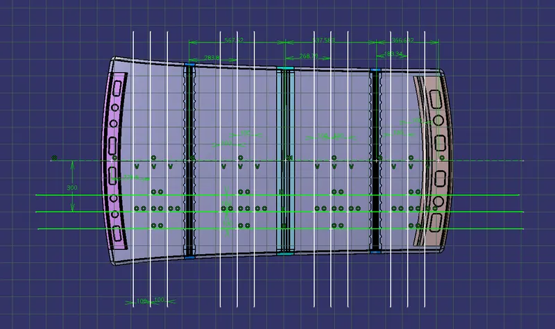
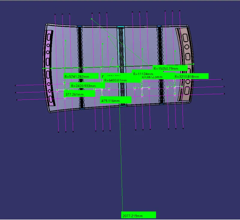
| S.NO | BOW'S | Rx | Ry | R | l | L | t | R^2/t | W | OK/NG |
| 1. | FR & BOW 1 | 5741.28 | 2420.93 | 3405.75 |
377.26 |
2077.2 | 0.75 | 15465510.75 | 1.613 | OK |
| 2. | BOW 1 & CR | 4921.80 | 6400.81 | 5564.70 | 479.11 | 2077.2 | 0.75 | 71287848.119 | 2.199 | OK |
| 3. | CR & BOW 2 | 3872.5 | 11124 | 5745.03 | 445.20 | 2077.2 | 0.75 | 44007159.60 | 2.216 | OK |
| 4. | BOW 2 & RR | 3210.81 | 15050.79 | 5292.55 | 243.654 | 2077.2 | 0.75 | 37348114 | 1.871 | OK |
B. Snow load Prediction formula:-
Qr = [Iy x t2] / [α x s x [(Rx + Ry)/2]2 x 10-8]
Note: The Qr value given over here is correct. There was a typo error in the formula given in the video.
Where
α = My x Lx2 x 10-12 , My = Y(Ly-Y)
Judgement condition = Qr ≥ 3.1
250 ≤ s ≤ 380
t = Roof plate thickness [mm]
Ly = Distance between the front and rear roof Rails on the Vehicle along with 0Y[mm]
Length of Roof panel with the center point between Roof rail Front /Rear as the reference point of the front and the rear.
Lx = Distance between the Left and Right end of the roof on the Roof BOW [mm]
Width of the roof panel exposed on the surface.
Y = Distance front Front Roof Rail to Roof BOW[mm]
s = Distance for which Roof BOW bears divided load [mm]
s = L1/2 + L2/2
Iy = Geometrical moment of inertia of Roof BOW (Y cross-section )[mm4]
Rx = Lateral direction curvature radius of roof panel Y cross-section on Roof BOW [mm]
Roof panel curvature Radius of the Length Lx in Front view
Ry = Longitudinal Direction curvature radius of the Roof panel X cross-section on Roof BOW [mm]
Roof panel X curvature radius of length s in Side view.
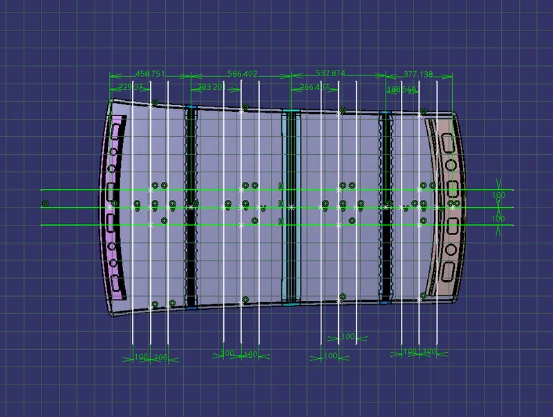
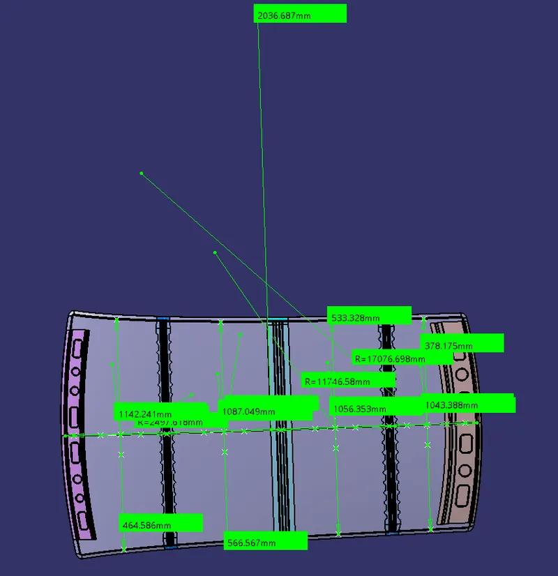
| S.NO | BOW's | Iy | α | s | Rx | Ry | t | Qr | OK/NG |
| 1. | FR & BOW1 | 239.2 | 0.95 | 515.57 | 4604.45 | 2497.61 | 1.25 | 6.05 | OK |
| 2. | BOW 1 & CR | 367 | 0.98 | 549.94 | 3776.19 | 6334.56 | 1.25 | 4.16 | OK |
| 3. | CR & BOW 2 | 255.1 | 0.89 | 455.75 | 4316.02 | 11746.58 | 1.25 | 1.52 | NG |
Section modulus For Bow roof 1 :-
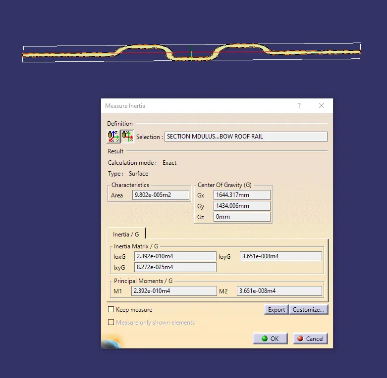
Iy = 2.392 e^-010 m^4
= 239.2 mm^4
y = 34.8395 mm
S = Iy / y
= 239.2 / 34.8395
S = 6.865 mm^3
Section modulus for center roof rail :-
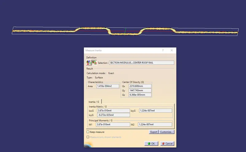
Iy = 3.67e^-010 m^4
= 367 mm^4
y = 52.4505 mm
S = Iy/ y
= 367/52.4505
S = 6.997 mm^3
Section modulus for Bow roof :-
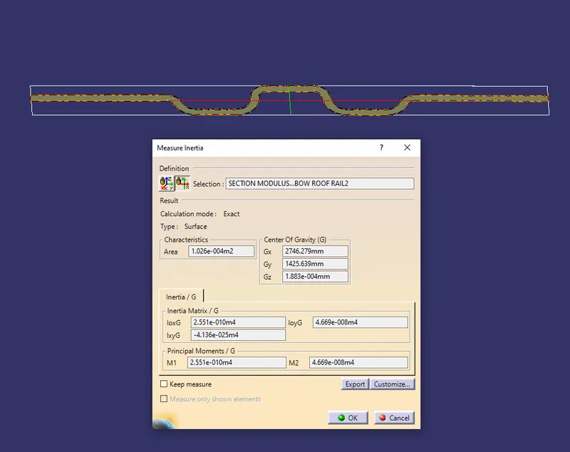
Iy = 2.551e^-010 m^4
= 255.1 mm^4
y = 38.4095 mm
S = Iy/ y
= 255.1/ 38.4095
S = 6.641 mm^3
DRAFT ANALYSIS :-
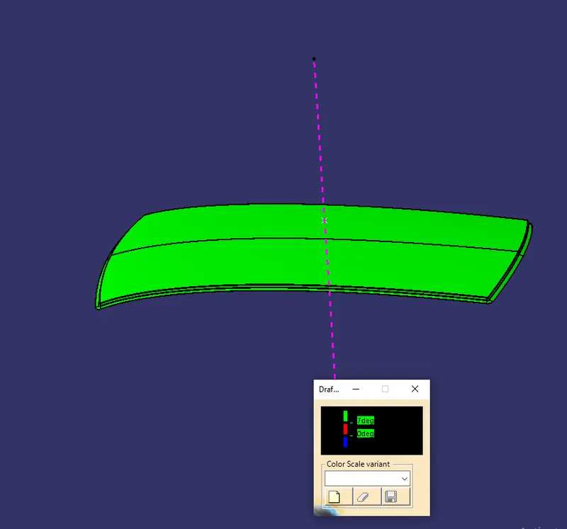
1. Draft analysis for Ditch area :-
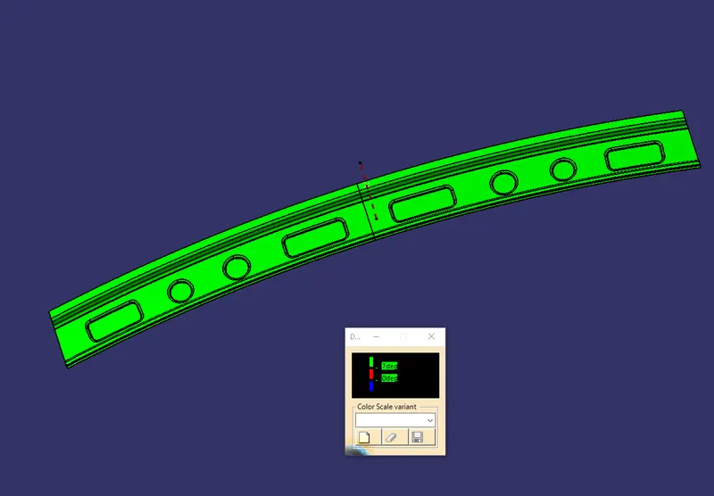
2. Draft analysis for Front roof rail :-
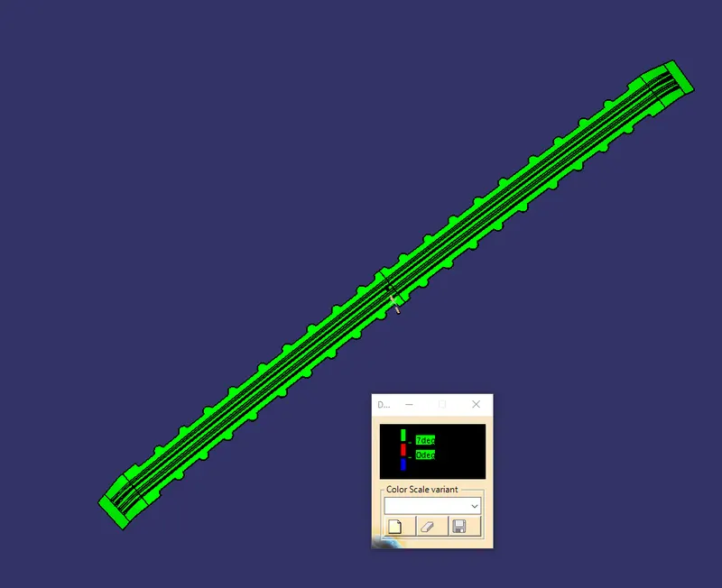
3. Draft analysis for Bow roof 1 :-
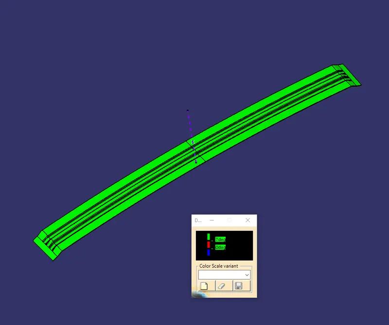
4. Draft analysis for Center roof rail :-
5. Draft analysis for Bow roof 2 :-
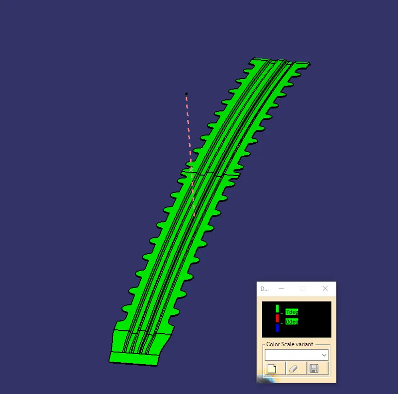
6. Draft analysis for Rear roof rail :-
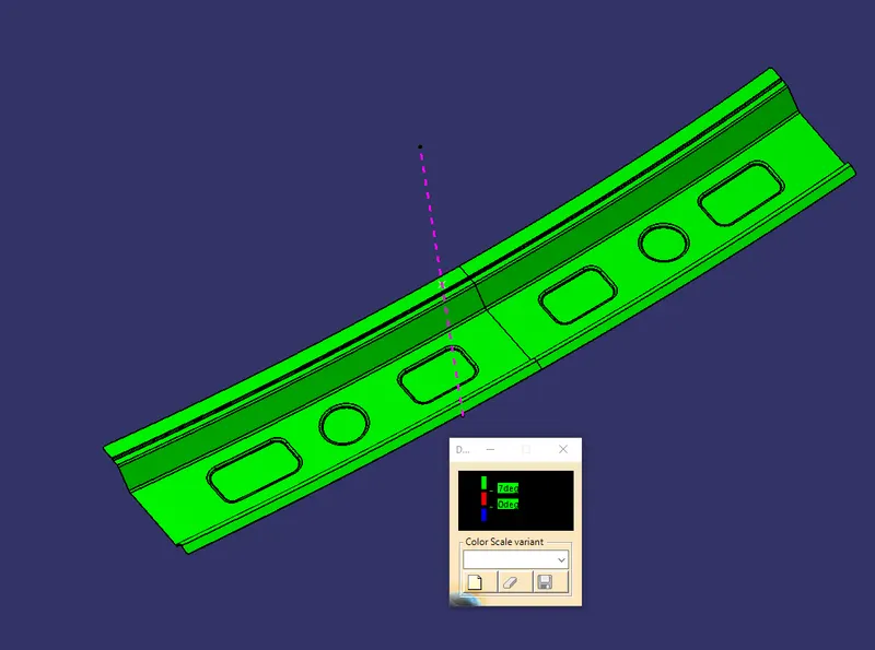
I have given maximum 7 degree deviation for all above areas . Anything within that limit is shown in green, which means that the part is producible.
CONCLUSION :-
Finally the reinforcements and Ditch Area for the Roof were designed and developed from the given styling. The curvature study was done after performing calculations for the Heat Distortion and Snow load conditions.
Then the Section Modulus study was conducted and Draft Analysis were done for each reinforcement succesfully.