Roof challenge
CAR ROOF:
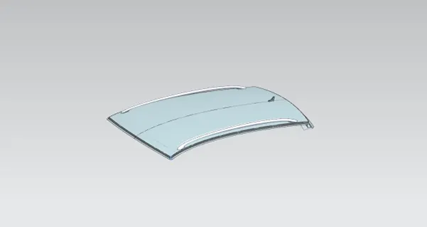
An automobile roof or car top is the portion of an automobile that sits above the passenger compartment, protecting the vehicle occupants from sun, wind, rain, and other external elements. Roof is the structure above the wind shield glass having the reinforcements to provide the strength to the overall structure and to with stand the over head forces like snow
REINFORCEMENTS :
If the roof is flat it is very weak and cannot able to with stand the forces like snow , so in order to increase the strength of the roof these reinforcements like front roof rail, central roof rail, rear roof rail and the bow roofs are introduced and joined to the flat surface of the roof with the different joining process
Different types of reinforcements that the car has are :
- Front roof rail
- Bow roofs
- Central roof rail and
- Rear roof rail
FRONT ROOF RAIL :
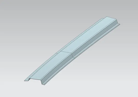
Front roof rail is the one which joins the wind shield glass , body side outer and the inner panel also. Here the front roof rail is designed based up on the master saection given
REAR ROOF RAIL :
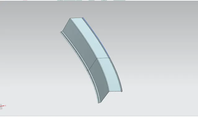
Rear roof rail is the one which joins the back door and the body side outer
CENTRAL ROOF RAIL :
central roof rail helps in providing effectively support to the flat area of the roof as it is more susceptible to failure under the action of load . generally central roof rail is placed at the center of the roof which is connected to the B-pillar support structure . This central roof rail helps in adding the strength to the roof during the rool- over test. The thickness of the central roof rail is 1.25 mm .
BOW ROOFS :
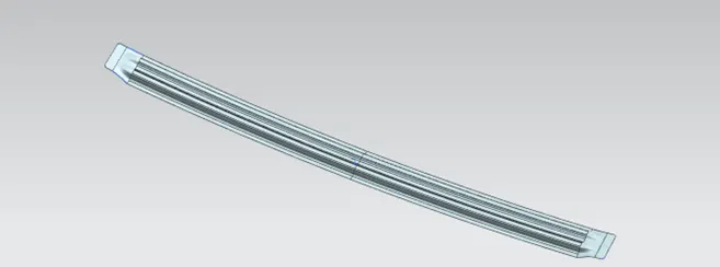
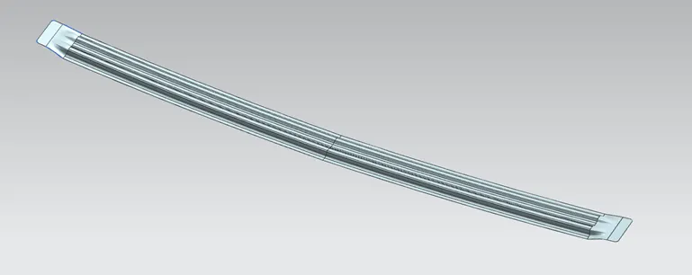
The bow roofs are give to improve the torsional stiffness and load bearing capacity of the roof structure . The number of bow roof present is depends on the overall size of the roof . Presently in this project two bow roofs are added.
JOINING PROCESS :
Mastics are introduced between the roof outer panel and the reinforcements for joining . where ever the mastic are introduced there is remarkable improve of the strength
Spot welding is also introduced to join the reinforcements and the outer panel
DESIGN CONSIDERATIONS FOR A ROOF :
- Visibility criteria
- Head clearance
- Curvature study
- Heat distortion and snow load criteria
- Draft analysis
ROOF CRUSH TEST :
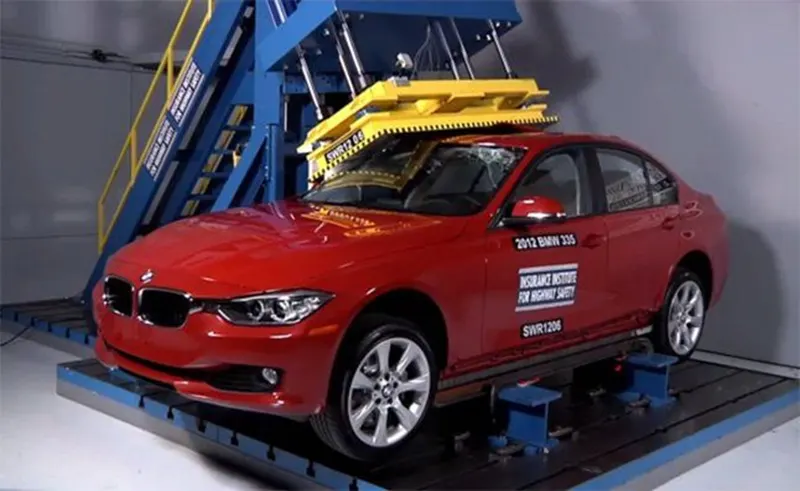
Roof crush test is the design given by the IIHS ( insurance institute of highway safety ) . After analyzing the many accidents IIHS has then fixed some regulations , that how to perform the crush test .
IIHS gives the rating based up on this test . For this they consider two points while giving the rating
How fast the car can reforms to its original shape after the roll over and
How deep is the protrusion after the roll over
GOAL OF ROOF CRUSH TEST :
To minimize the protrusion into the occupant compartment , so that the seat belts and air bags can do there job in protecting the occupant
CONDITIONS TO FOLLOW FOR ROOF CRUSH TEST :
There are two conditions that should be followed for the roof crush test , they are
INITIAL CONDITION :
Close and lock all the doors
Close all the windows
SECOND CONDITION :
Fix the body sill or chassis frame on a hard lever surface horizontally
METHOD OF APPLYING THE FORCE :
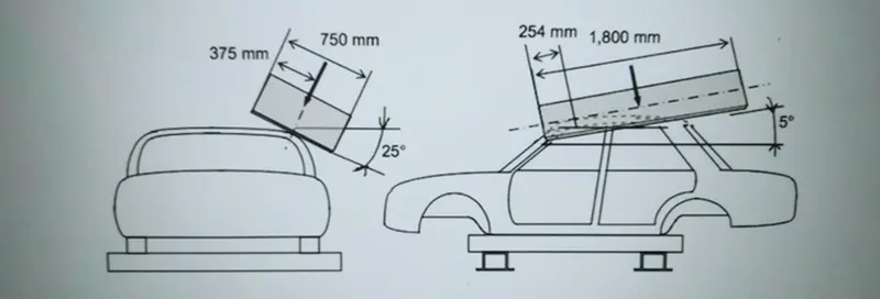
The load is applied in such a way that 50 is tilted from the front end to the rear end and the load will be in 1800 mm in length and 750 mm in width . The load is applied at the position of 250 from the flatness of the roof . The load is applied on the roof for almost 120 sec and the crush speed at which the load applied is 13 mm/sec or less than that
RESULTS :
If the displacements goes above the requirements level then we have to increase the bow roof thickness or add more mastics points to increase the strength . the stronger the roof the better it can protect the occupants in the roll over crashes.
HEAT DISTORTION STUDY ON THE ROOF :
The heat distortion study plays a major role in sheet metal usage . heat distortion temperature is a temperature limit above which the material cannot be used for the structural applications . This study is used to predict the heat distortion temperature at where the material starts to soften when exposed to a fixed load at elevated temperature . In order to avoid bending or damages on the roof, based on the heat distortion temperature , this study will predict the bow roof position which helps to strengthen the roof .
Bow – roof prediction Formula
W = [1.73 x 10^(-3) x L] + [1.85 x 10^(-8) x (R^2)/t] + [ 1.10x10^(-3) x l] - 2.68
Where
L = Roof Length in X-Direction[mm](Roof dimension in 0-Y)
R = Roof curvature
R = 2(Rx*Ry)/(Rx+Ry)
Rx = X curvature
Ry = Y curvature
t = Roof plate thickness [mm]
l = Bow Roof Span [mm]
Judgement Condition: OK< 2.7> 3.1
APPLY THE VALUES IN THE FORMULA:
In order to find the heat distortion apply all the necessary values from the roof to the give formula
CALCULATIONS:
|
HEAT DISTORTION CRITERIA CALCULATIONS |
||||||||
|
ROOF RAILS |
RX |
RY |
R |
L |
T |
I |
W |
RESULT |
|
FR-BOW 1 |
5724.6180 |
2750.9253 |
3716.1031 |
2131.1 |
0.75 |
422.64 |
1.8123 |
PASS |
|
BOW 1-CR |
4886.9253 |
6542.8321 |
5594.5381 |
2131.1 |
0.75 |
422.0046 |
2.2430 |
PASS |
|
CR-BOW 2 |
3963.8767 |
10650.6117 |
5777.5748 |
2131.1 |
0.75 |
419.9575 |
2.2921 |
PASS |
|
BOW 2-RR |
3296.9063 |
1450.0642 |
2014.2182 |
2131.1 |
0.75 |
311.8464 |
1.4499 |
PASS |
From the above table it can be concluded that all values of w<2.7 and also not w>3.1 so thus infers that current positioning of bow row are good in state as per design and found ok
SNOW LOAD CRITERIA:

This test is done to know how is the roof behaving when there is a snow over. normally due to the snow weight the dent will happen. But the roof should be designed in such a way that when the snow is removal the roof should go it its original position. This is the basic requirements for snow load criteria.
Qr =[Iy x t2] / [α x s x [(Rx + Ry)/2]2 x 10-8]
Where
α = My x Lx2 x 10-12 , My = Y(Ly-Y)
Judgement condition = Qr ≥ 3.1
250 ≤ s ≤ 380
t = Roof plate thickness [mm]
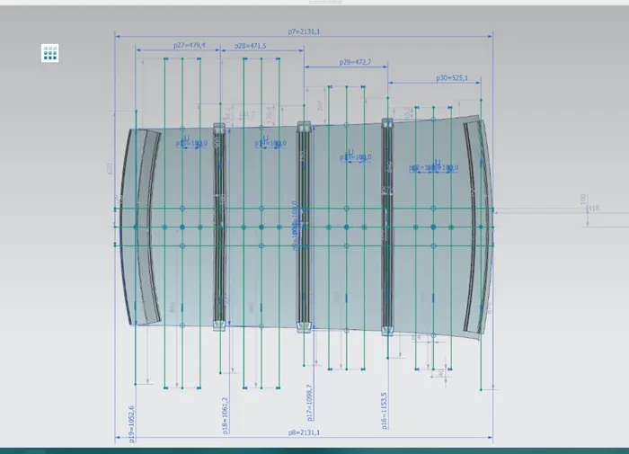
Ly = Distance between the front and rear roof Rails on the Vehicle along with 0Y[mm]
Length of Roof panel with the center point between Roof rail Front /Rear as the reference point of the front and the rear.
Lx = Distance between the Left and Right end of the roof on the Roof BOW [mm]
Width of the roof panel exposed on the surface.
Y = Distance front Front Roof Rail to Roof BOW [mm]
s = Distance for which Roof BOW bears divided load [mm]
s = L1/2 + L2/2
Iy = Geometrical moment of inertia of Roof BOW (Y cross-section) [mm4]
Rx = Lateral direction curvature radius of roof panel Y cross-section on Roof BOW [mm]
Roof panel curvature Radius of the Length Lx in Front view
Ry = Longitudinal Direction curvature radius of the Roof panel X cross-section on Roof BOW [mm]
SECTION MODULUS :
Section modulus is a geometric property for a given cross-section used in the design of beams or flexural members. Other geometric properties used in design include area for tension and shear, radius of gyration for compression, and moment of inertia and polar moment of inertia for stiffness. Any relationship between these properties is highly dependent on the shape in question. Equations for the section moduli of common shapes are given below.
There are two types of section moduli:
The elastic section modulus and
The plastic section modulus.
The elastic section modulus is defined as
S = I / y
where:
S= Section modulus
I = second moment of inertia (or area moment of inertia, not to be confused with moment of inertia)
y = the distance from the neutral axis to any given fibre. It is often reported using y = c, where c is the distance from the neutral axis to the most extreme fibre
BOW ROOF 1
Create an intersection curve with the help of the plane and select the bow roof 1
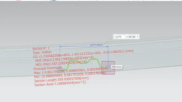
SECTION MODULUS
S= moment of inertia /distance from the neutral axis to any given fibre
S = I / y
Y = 35 mm
FOR MAXIMUM MOI:
S= 2.9911*103mm4/35mm
S max = 85.46mm3
BOW ROOF 2
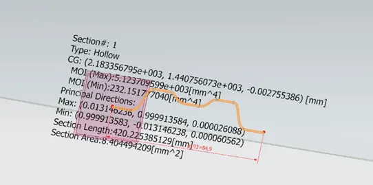
SECTION MODULUS
S= moment of inertia /distance from the neutral axis to any given fibre
S = I / y
Y = 35 mm
FOR MAXIMUM MOI :
S= 3.0029 *10 3mm4) / 35mm
S max = 85.7971 mm3
CENTRAL ROOF RAIL:
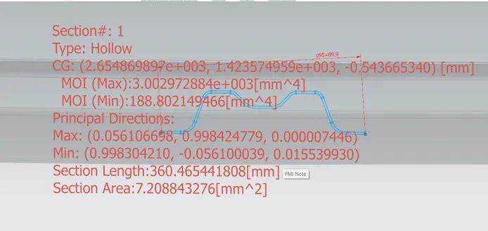
SECTION MODULUS
S= moment of inertia /distance from the neutral axis to any given fibre
S = I / y
Y = 42.5mm
FOR MAXIMUM MOI:
S= 5.1237*10 3 (mm4) / 42.5mm
S max = 150.5576 mm3
APPLY THE VALUES IN THE FORMULA:
In order to find the snow load criteria apply all the necessary values from the roof to the give formula
CALCULATIONS:
|
SNOW LOAD CREITERIA |
|||||||||
|
ROOF RAILS |
IY |
LX |
LY |
T |
RX |
RY |
Y |
Q |
RESULT |
|
FR-BOW-1 |
85.46 |
2131.1 |
1153.5 |
0.75 |
4441.378 |
2733.369 |
525.1 |
0.89404 |
FAIL |
|
BOW 1-CR |
150.5576 |
2131.1 |
1098.7 |
0.75 |
3784.446 |
6466.548 |
472.7 |
0.9066 |
FAIL |
|
CR-BOW 3 |
85.7971 |
2131.1 |
1061.2 |
0.75 |
4281.030 |
11156.513 |
471.5 |
0.2414 |
FAIL |
It is observed from the values that obtained values of QR > 3.1
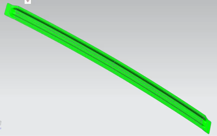
DRAFT ANNALYSIS:
ROOF OUTER PANNEL
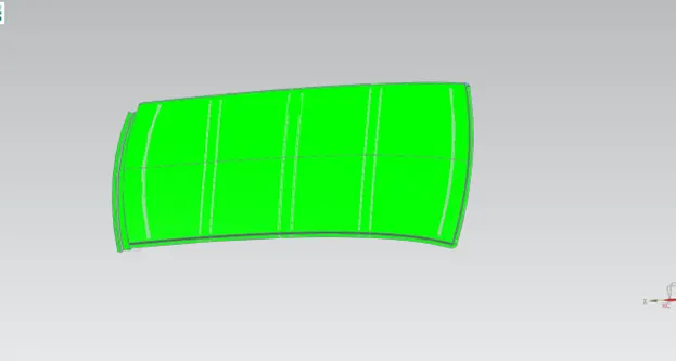
ROOF FROUNT RAIL
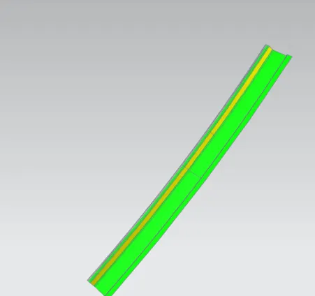
ROOF REAR RAIL
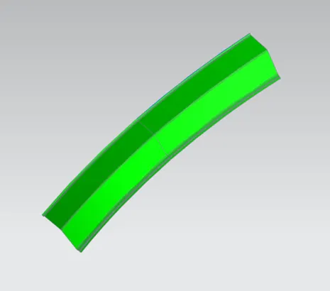
BOW ROOF 1
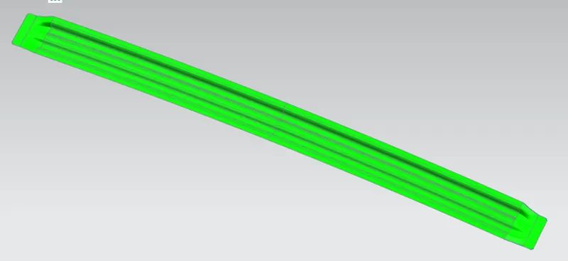
CENTER ROOF RAIL 2
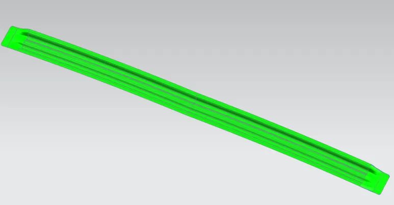
BOW ROOF 2
CONCLUSION:
By this report we have designed roof and its parts according to the master sketch .we have also analysed our roof with various method process.