Roof challenge
OBJECTIVE:
To develop the essential flanges and reinforcements with appropriate dimensions and checking draft by performing Draft analysis, Calculating Section inertia, Heat distortion and Snow load on the roof.
A dumb solid body of roof CAD model is provided for which following points to be designed and analyzed are as follow,
- Extracting the styling surface and for the given car roof styling and design the essential flanges and reinforcement, namely Ditch Area, Front Roof Rail, Rear Roof Rail, Centre Roof Rail, and Bow-Roofs.
- Do a curvature study on the roof and perform calculations for Heat Distortion and Snow load criterion to determine and justify the position of the Bow-roofs.
- Finding a moment of inertia and Section Modulus for Bow Roof Rails and Centre Roof Rail.
- Perform a Draft Analysis of each reinforcement.
BIW Manufacturing Process
Mechanical and hydraulic presses are commonly used for press operation due to wide range of sizes, tonnage capacities, stroke lengths, and operating speeds.
- Blanking parts at high speed
- Automatically fed with a short feed length
- Shallow drawing
- Work requiring an easily controlled depth of stroke
- Deep drawing
- Short runs with frequent die changes
- Blanking with a form, or coin
- Lower speed high tonnage blanking with long feed lengths
- Work requiring repeatable pressure
- Simplify the design suitable for die design or combination of operations
- Design a components such that it will combine the components in case of tailor welded blanks
- Reduce depth of component to avoid number of draw operations
- Minimize number of operations required to finish the components
- Process to be choose for stamping depends on the design and complexity of component
- Usually blanking, drawing, piercing, forming, notching, trimming, hemming operations are largely used in automotive stamping applications
- Normally sheets are supplied in the form of rolls for mass manufacturing.
- To make components the sheets are cut down into the correct shape of component called as 'Blank'.
Shearing process (Cutting material)
- Punching
- Blanking
- Perforating
- Parting
- Notching
- Lancing
- Nibbling
- Slitting
- Tailor welded blank
- Shear Spinning
Forming process (Bending and stretching)
- Bending
- Stretching
- Drawing
- Re-draw
- Roll forming
- Explosive forming
- Hydro forming
Finishing process (to maintain surface and geometry quality)
- Trimming / laser trimming
- Flanging / Cam flanging
- Hemming
- Part off
- Beading
Introduction:
An automobile roof or car top is the portion of an automobile that sits above the passenger compartment, protecting the vehicle occupants from sun, wind, rain, and other external elements. Roof is the structure above the wind shield glass having the reinforcements to provide the strength to the overall structure.
An automobile roof or car top is the portion of an automobile that sits above the passenger compartment, protecting the vehicle occupants from sun, wind, rain, and other external elements.
In later years, many variations on the automobile roof developed. These include:
Types Of Car Roofs
- Convertible roofs

- Hardtops
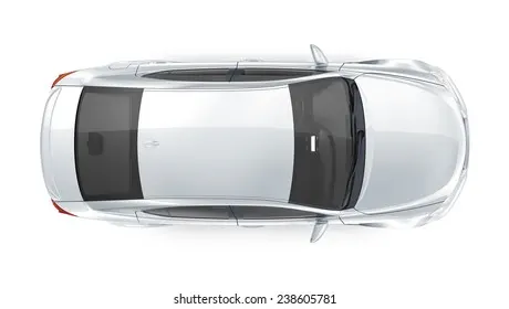
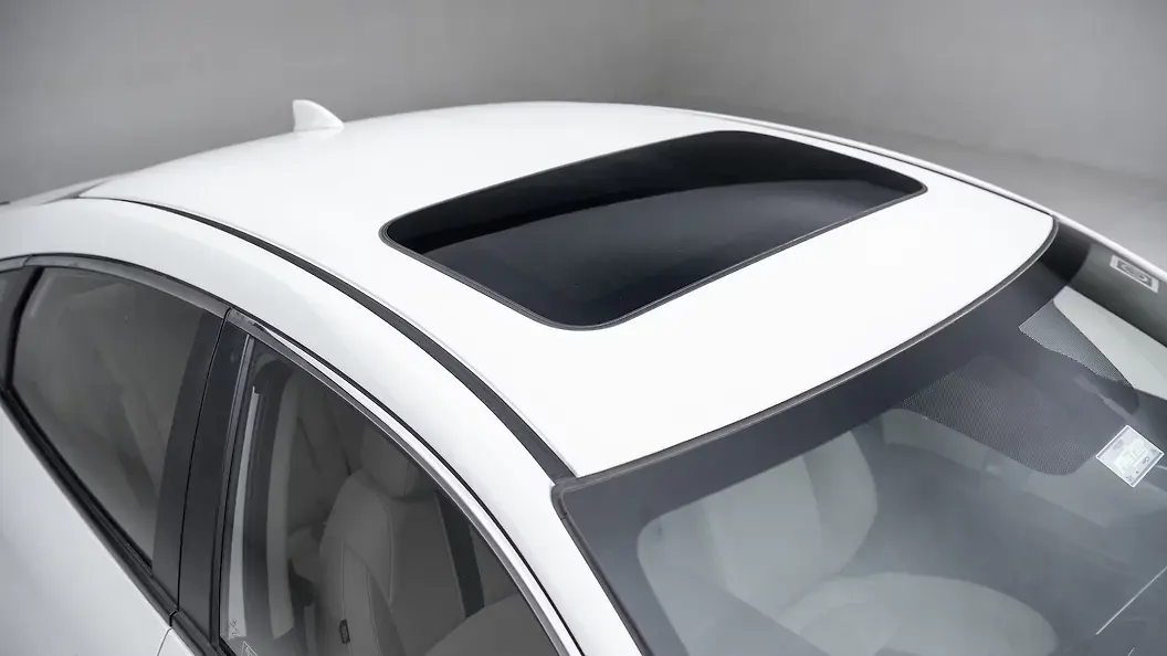
- Sunroofs
- T-Tops
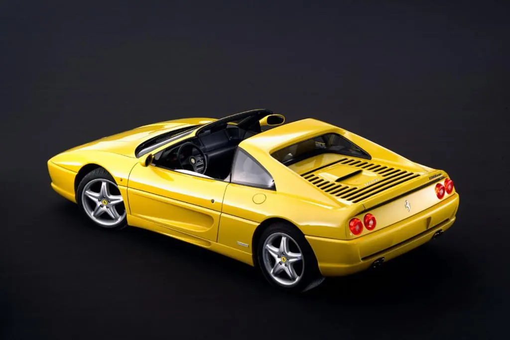
- Targa Tops
- Vinyl Roofs

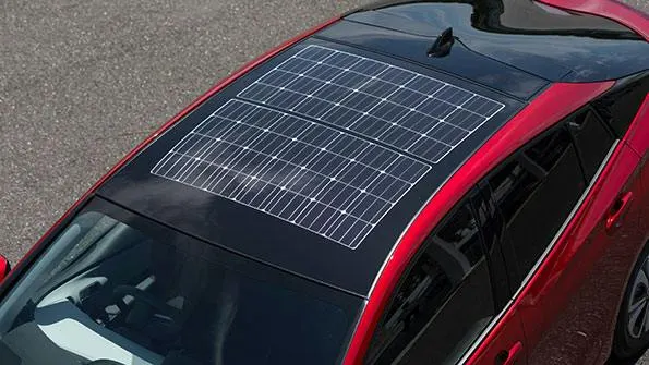
- Solar Panel Roof
ROOF CRUSH TEST
In this test the vehicle roll over strength is evaluated by giving induced force to the roof of automotive. The roof has to be much elastic to recover from deformation, which gives good rating. The distance of protrusion inside the vehicle due to crush load increases the fatality rate of passengers.
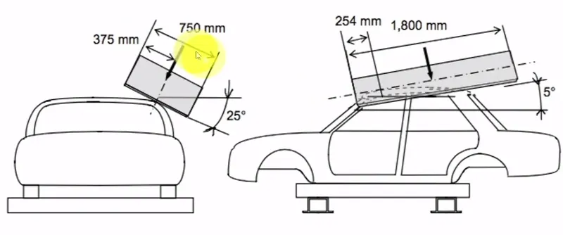
This test can be conducted on either side of the roof structure, the front left or front right side but not on both sides in one single test and still meet the requirements of the test. The rigid plate shall not move faster than 0.5 inches/second and the force applied on the plate shall not exceed the lesser of 1.5 times the unloaded vehicle weight (UVW) expressed in kilograms multiplied by 9.8 or 5000lbs
The displacement of load applied is 127mm generally. The load is given with Xc and Yc inclinations of about 25 degrees, 5 degrees respectively. The crush speed of load applied is 13mm/sec. Time taken for completion of test is 120 seconds.
Why using reinforcements ?
If the roof is flat it is very weak and cannot able to with stand the forces like snow, so in order to increase the strength of the roof these reinforcements like front roof rail, central roof rail, rear roof rail and the bow roofs are introduced and joined to the flat surface of the roof with the different joining process.
Beasic criteria must follow while designing such as they are :-
- Visibility Criteria
- Head clearance
- Curvature study
- Heat distortion and snow load criteria
- Draft analysis.
- Safety parameters
Input Data for desiging the Bows Roof & Roof Rails :
Roof Skin
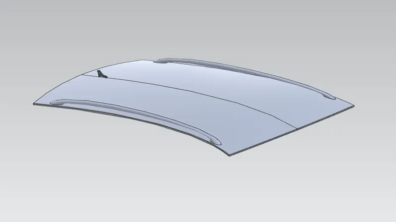
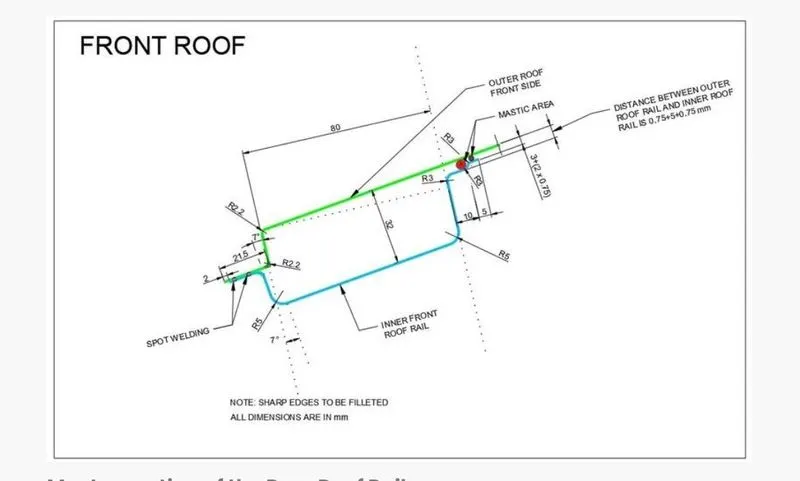
Master Section of Front Roof Rail
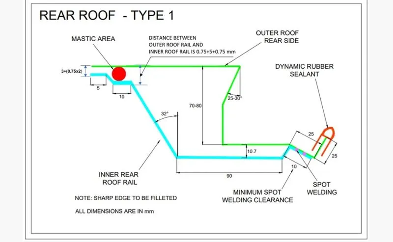
Master section of Rear Roof Rail
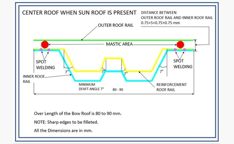
Master section of center Roof Rail With Reinforcement
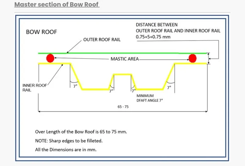
Master Section of Bow Roof
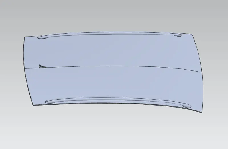
Styling Surface to Extracted Surface:
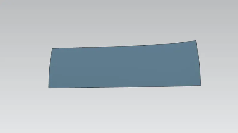
The styling team has provided the solid dump outer panel from that we are extracting the surface to model the necessary reinforcements like Ditch area, Front Roof Rail, Bow Roof Rails,Centre Roof and Rear Doof Rail.
Styling suface
Extracted Surface
Design a Ditch Area for Outer Roof Panel:
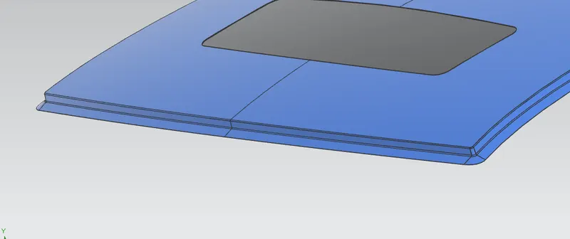
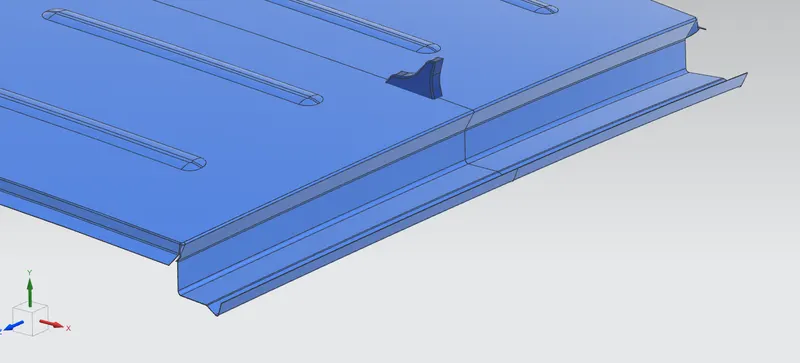
Styling team provided the master section for the roof ditch area, front roof rail and rear roof rail as per the parameter of visibility criteria, head room clearance and other important parameter dimension like fitment of windshield, sealant rubber etc. All these data are well calculated in the planning stage to design the peripheral component accordingly. Thus, here designing is done just to replicate those input data considering engineering parameters which should be feasible for manufacturing. Master section of front and rear section.
Front Ditch Area
Rear Ditch Area
FRONT ROOF RAIL:
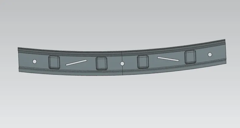
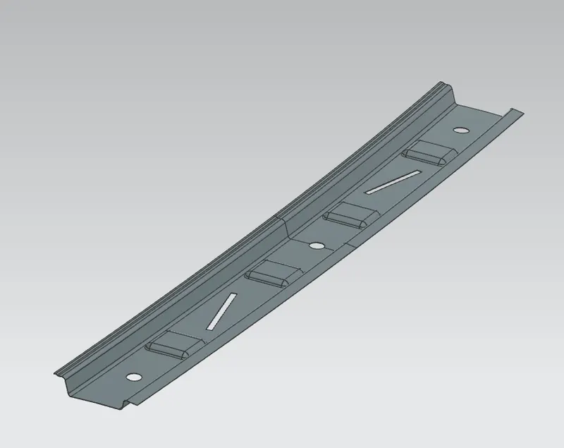
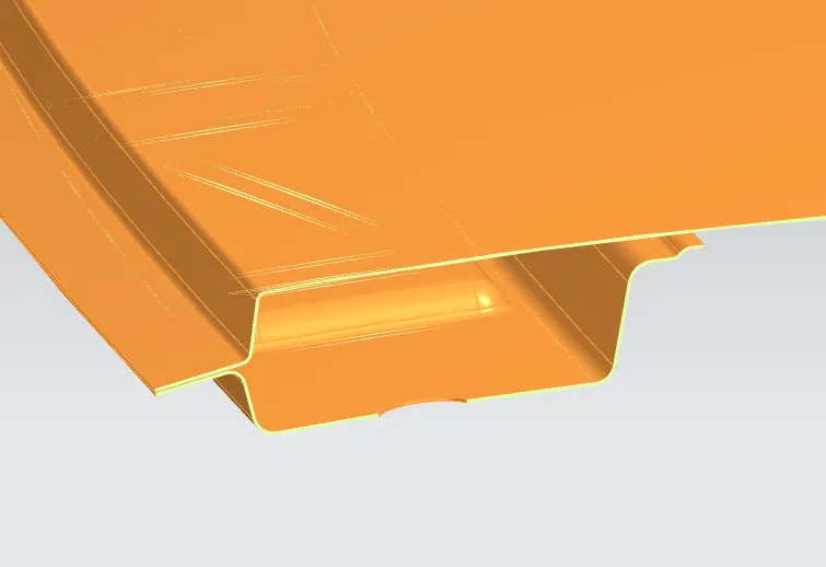
The master sketch has all the geometrical details for front roof. A space for about 21 mm is provided for windshield, rubber lining and mastic. The drawing angle is kept open for about 3degrees. The sealant requires at least of minimum 5mm gap. Whenever the inclination were provided for flanges the visibility criteria and the drawability has to be considered. The offset surface distance 32mm depends on the visibility of driver and enough head room clearance. The 80mm length depends on surface match with outer panel and also provides enough cabin clearance. On the right side of roof rail a clearance of about 3mm is given for mastic. Corner relief are given to deviate the stress concentration point.
MASTER SECTION OF FRONT ROOF RAIL
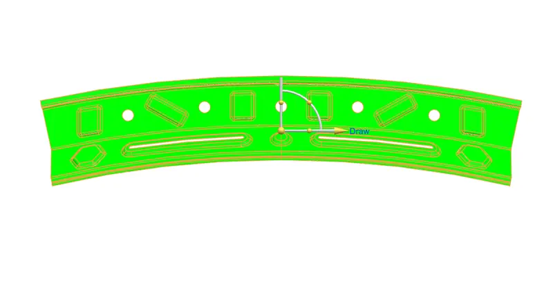
DRAFT ANALYSIS OF ROOF RAILS:
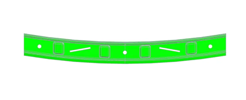
Draft analysis is done to check whether the part has any negative drafts which is miserable for manufacturing. The limiting angle of negative is 5 degrees.
DRAFT ANLYSIS OF FRONT ROOF RAIL
1st BOW ROOF:
It is used to give strength to the area between the front roof and the centre roof rail. Also it is created in the area between the centre roof rail and the rear roof rail to provide enough strength. It can be created in any numbers depending upon the roof length but the position of the bow roofs is to be justified by curvature study.
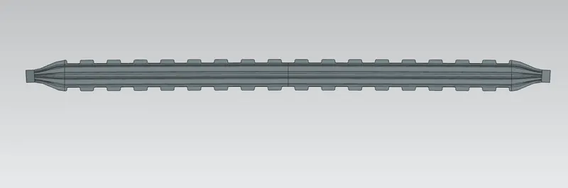
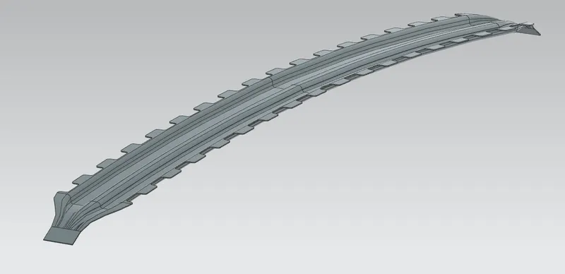
MASTER SECTION OF FRONT BOW ROOF
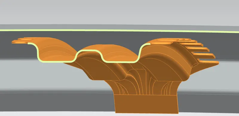
DRAFT ANLYSIS OF FRONT BOW ROOF
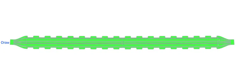
CENTER ROOF RAIL:
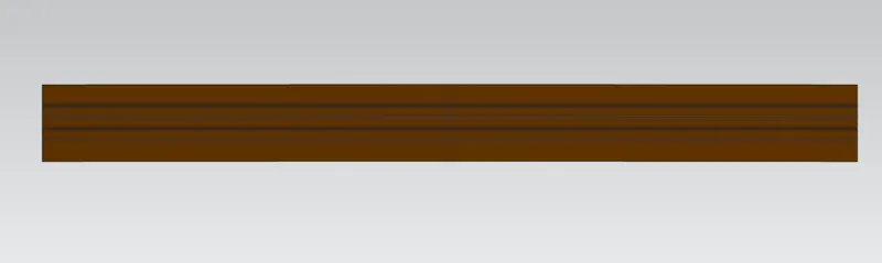
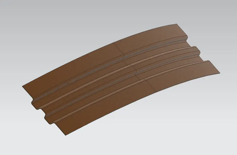
Here the minimum thing we need to take care is the width of the Center Roof Rail should be between 80-110.By following the master section by styling team the physical shape shown below.
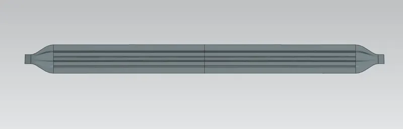
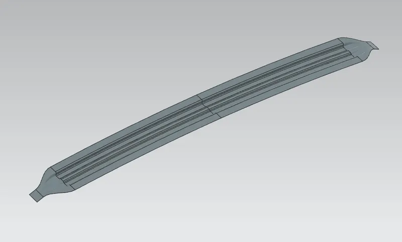
CENTER ROOF RAIL REINFORCEMENT:
It is attached with center roof rail with help of spot welding.
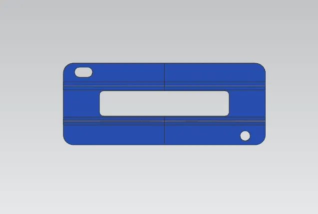
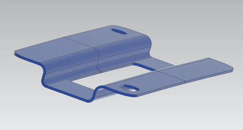
CABIN LIGHT MOUNT:
Its having mounting hole and slot.
ASSEMBLED ROOF RAIL:
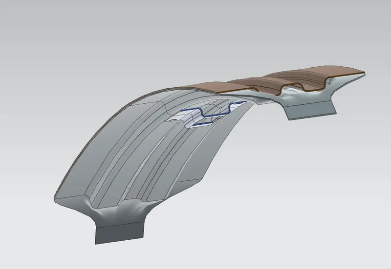
MASTER SECTION OF CENTER BOW ROOF
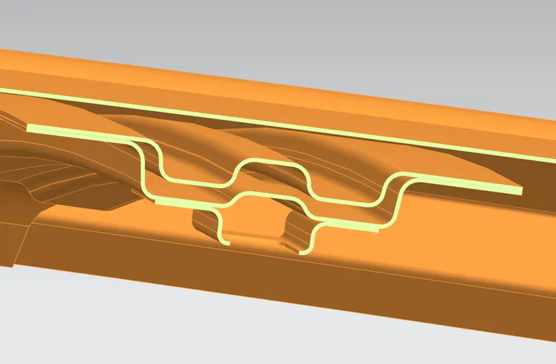
DRAFT ANLYSIS OF CENTER ROOF RAIL
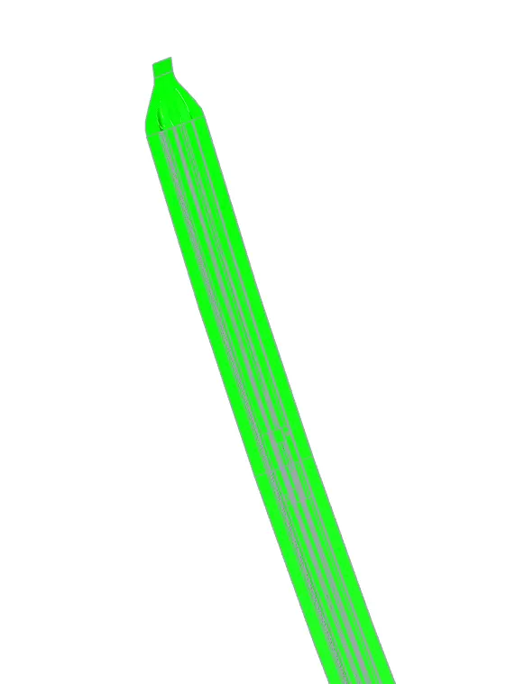
2ND BOW ROOF:
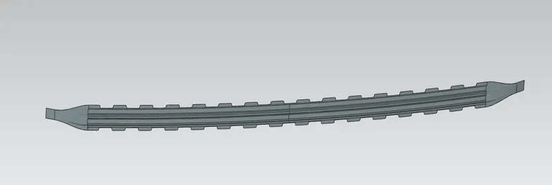
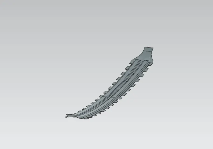
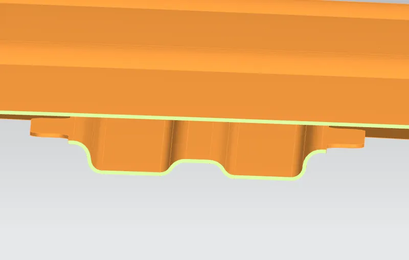
MASTER SECTION OF REAR BOW ROOF
REAR ROOF RAIL:
While designing the rear roof rail we need to take care of the head clearance of the passenger & the Rear Visibility Criteria.
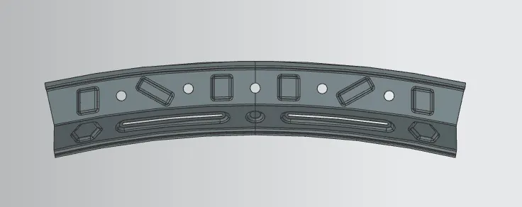
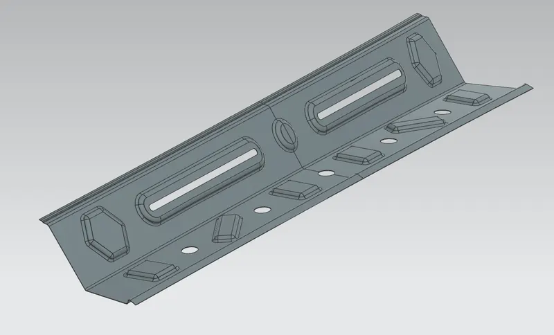
MASTER SECTION OF REAR ROOF RAIL
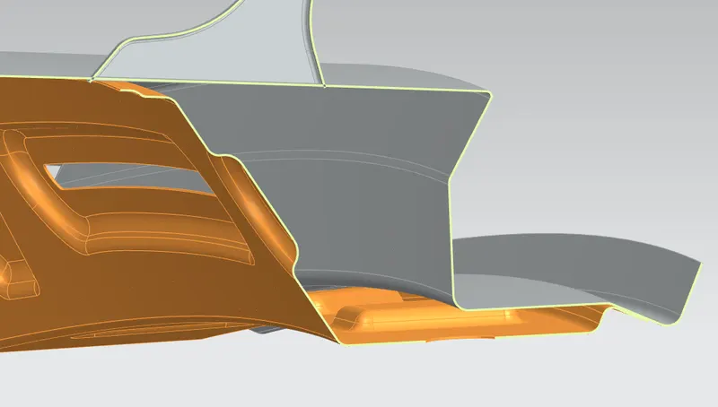
DRAFT ANLYSIS OF REAR ROOF RAIL
ROOF:
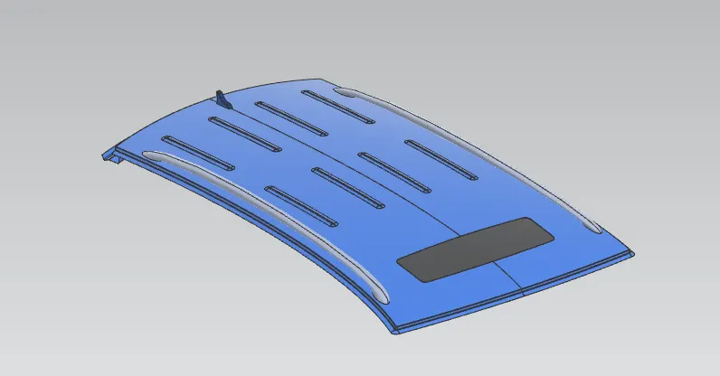
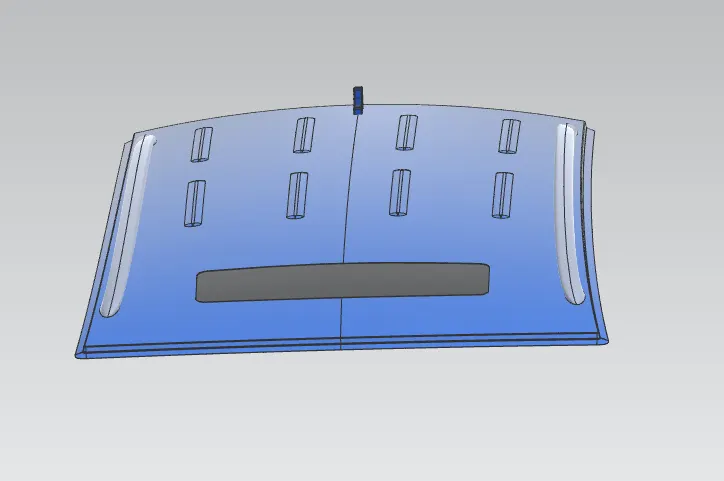
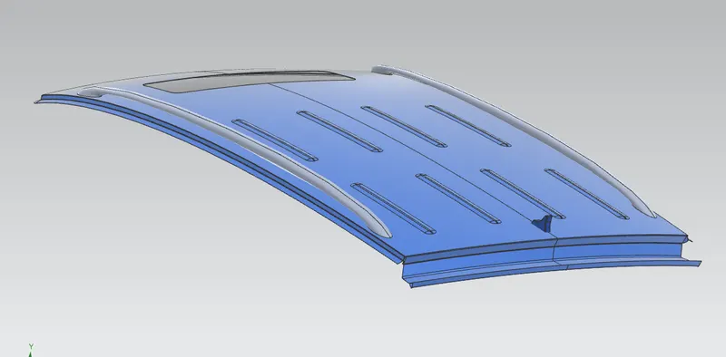
DRAFT ANLYSIS OF ROOF
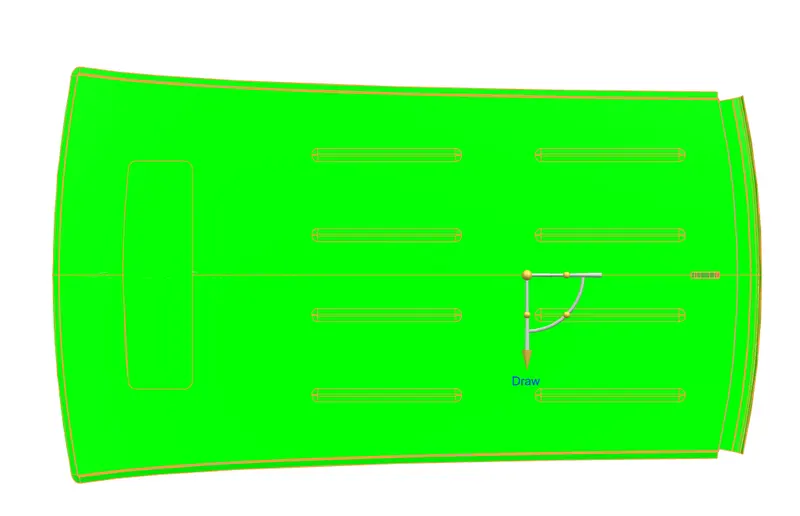
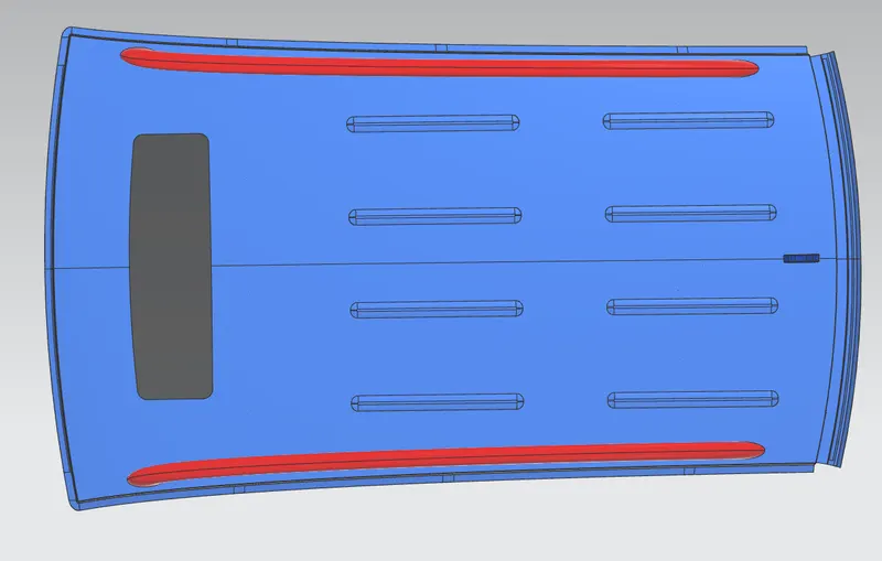
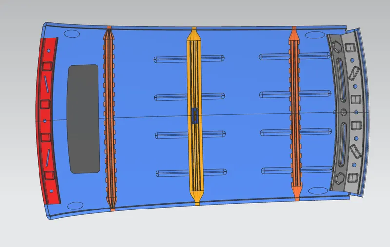
FINAL ASSEMBLED DESIGN :
TOP VIEW
BOTTOM VIEW
SIDE VIEW
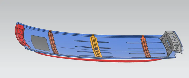
After completing design there are some calculation can be done by us to calculate the strength of the Designed Roof.
Curvature Study on the Roof:
The heat distortion study plays an important role in sheet metal usage. Heat distortion temperature is a temperature limit above which the material cannot be used for structural applications. This study is used to predict the heat distortion temperature at where the material starts to soften when exposed to a fixed load at elevated temperature. In order to avoid bending or damages on roof, based on heat distortion temperature, this study will predict the bow roof position on the roof to strengthen the roof.
HEAT DISTORTION CRITERIA
Heat Distortion Calculation
The material softens under increased temperature conditions. While applying load at this state makes the material much vulnerable to static loads. So to formulate this scenario the heat distortion criteria is introduced. The formula for heat distortion criteria is
W = [1.73 x 10^(-3) x L] + [1.85 x 10^(-8) x (R^2)/t] + [ 1.10x10^(-3) x l] - 2.68
Judgement Condition : OK< 2.7> 3.1
Where
L = Roof Length in X-Direction[mm](Roof dimension in 0-Y)
R = Roof curvature
R = 2(Rx*Ry)/(Rx+Ry)
Rx = X curvature
Ry = Y curvature
t = Roof plate thickness [mm]
l = Bow Roof Span [mm]
Except Rx and Ry all values can be measured on the model.
To get the Rx and Ry curvature a sketch was required-
- A sketch was created on a plane on top of the Roof
- 0-Y line was created in the X-Direction in center of roof
- Then a Horizontal line below 300mm was created named as -3Y Line
- Two lines on both sides at 100mm were created from -3Y Line

- Intersection point on line was created and projected on outer Panel of Roof
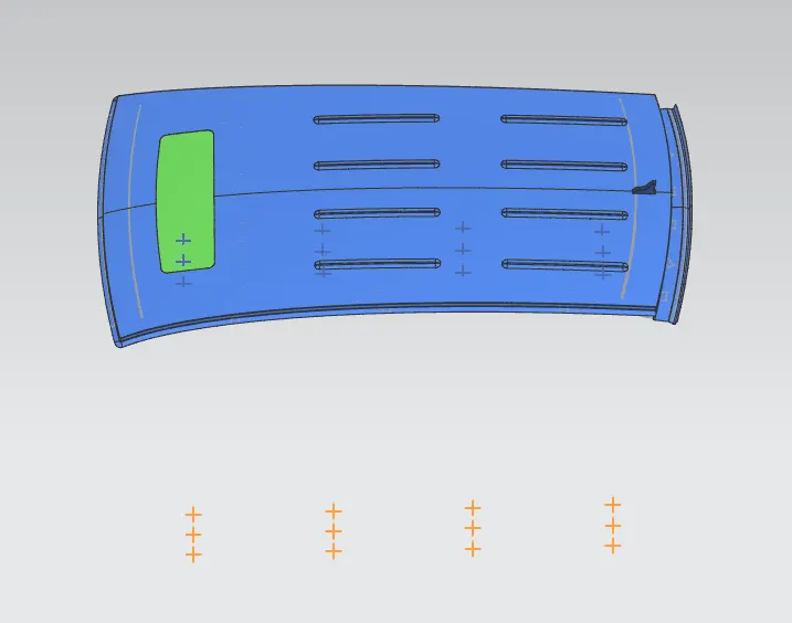
- Create the arc between projected point
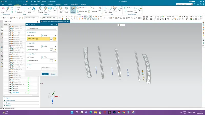
Rx ( FR & 1ST )
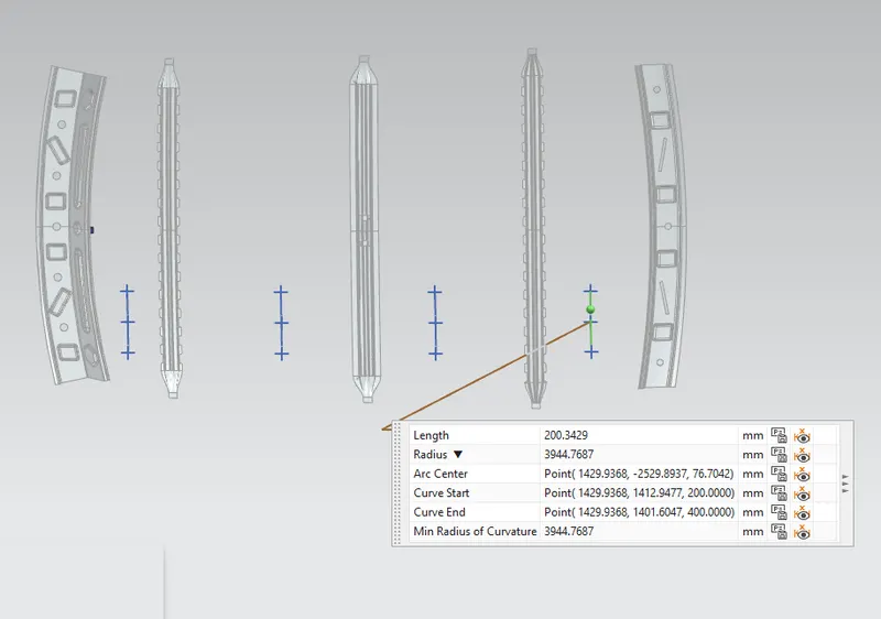
Rx ( 1ST & CTR )
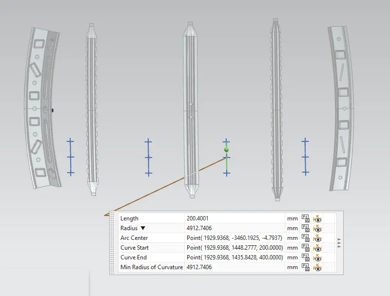
Rx (CTR & 2ND )
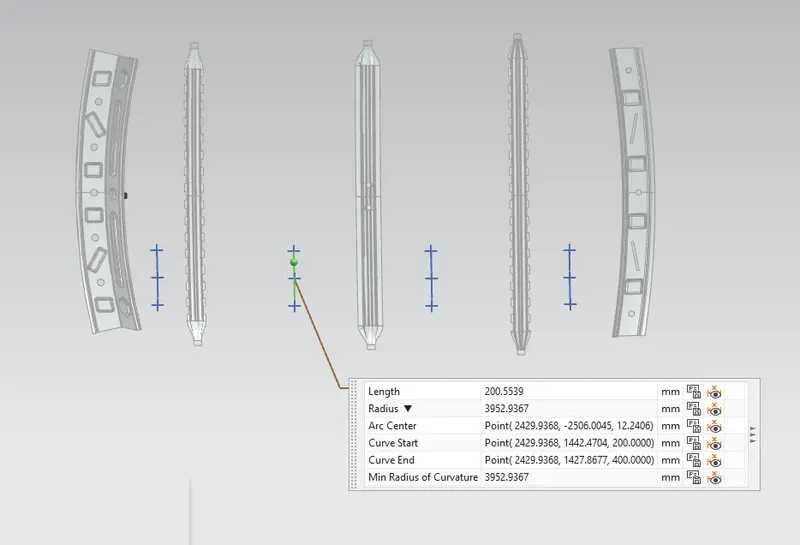
Rx ( 2ND & RR )
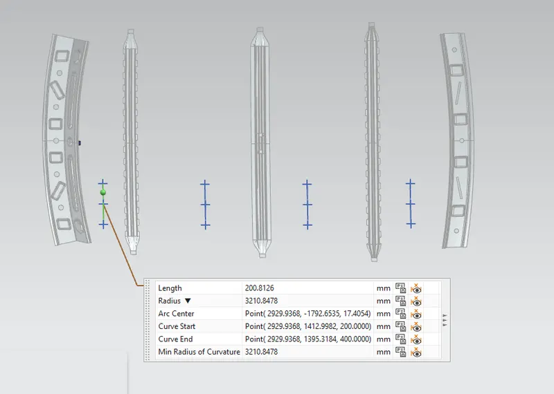
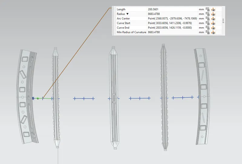
Ry (FR & 1ST)
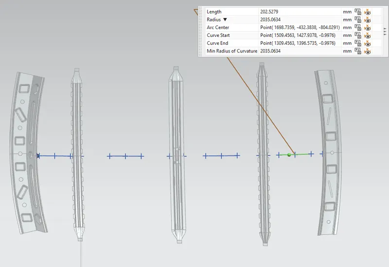
Ry ( 1ST & CTR )
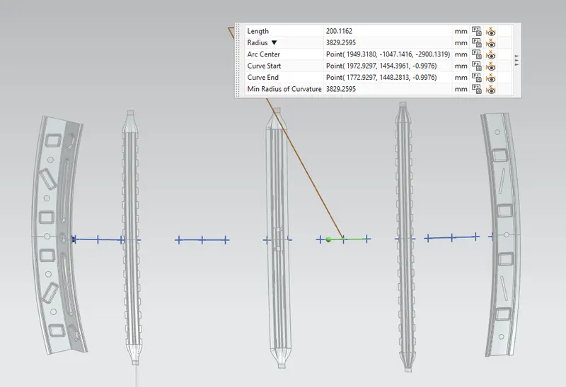
Ry ( CTR & 2ND)
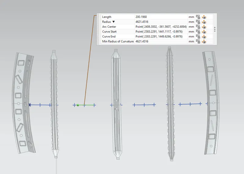
Ry ( 2ND & RR )
Apply the values in the formula:
To find the Heat distortion apply all the necessary values from the Roof to the given formula.
| s.no | BOWs | Rx | Ry | R | l | L | t | R^2/t | W | OK/NG |
| 1 | FR & 1st | 3944.76 | 2035.06 | 2684.97 | 340.85 | 2034 | 0.75 | 9612085.2 | 1.39 | OK |
| 2 | 1st & CTR | 4912.74 | 3829.25 | 4303.85 | 468.88 | 2034 | 0.75 | 24697499.76 | 1.81 | OK |
| 3 | CTR & 2nd | 3952.93 | 4621.45 | 4265.6 | 557.72 | 2034 | 0.75 | 24260457.81 | 1.9 | OK |
| 4 | 2nd & RR | 3210.84 | 8683.47 | 4850.13 | 223.03 | 2034 | 0.75 | 31365014.69 | 1.66 | OK |
According to Judgement Condition : OK< 2.7> 3.1
All Values are under Judgement Condition.
Section modulus study of the Roof Rails:
The section modulus of the cross-sectional shape is of significant importance in designing of structures. It is a direct measure of the strength of the structure
A structure that has a larger section modulus than another will be stronger and capable of supporting greater loads.
SECTION OF FRONT BOW ROOF
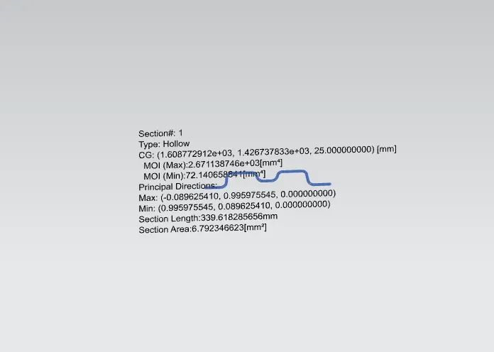
SECTION OF CENTER ROOF RAIL
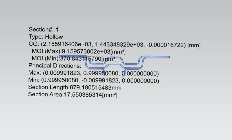
SECTION OF REAR BOW ROOF
Snow load criteria calculations
Snow load criteria is useful to justify the bow roof rail position in snow fall regions. Due to snow fall snow will get collected on the top roof which will tend to bend the roof. Bow roof will be at such position which will provide more strength to roof against bending.
Qr = [Iy x t2] / [α x s x [(Rx + Ry)/2]2 x 10-8]
α = My x Lx2 x 10-12 , My = Y(Ly-Y)
s = L1/2 + L2/2
All necessary measurements
Lx (FR & 1ST )
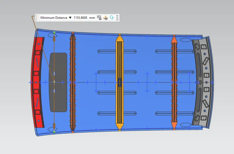
Lx (1ST & CTR )
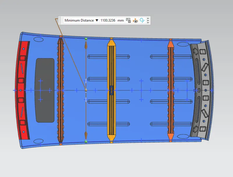
Lx (CTR & 2ND )
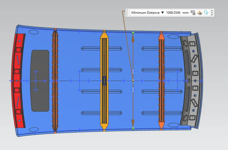
Lx ( 2ND & RR )
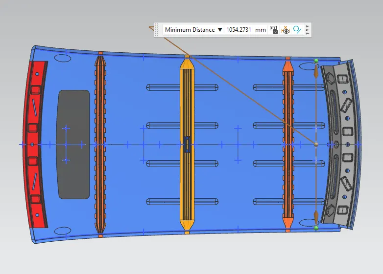
Ly ( FOR ALL)
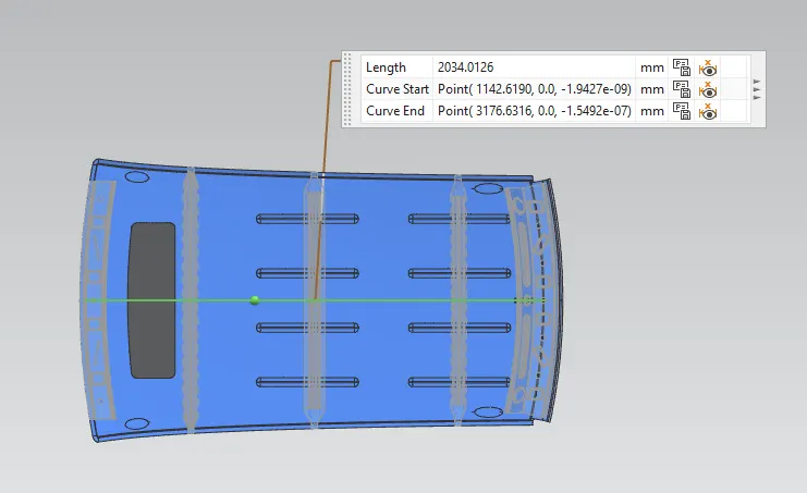
Rx ( FR & 1st )
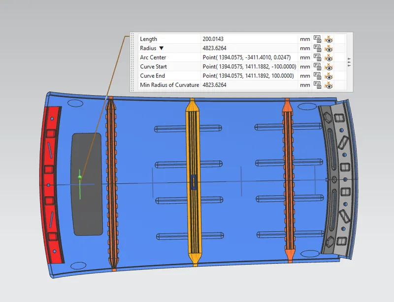
Rx ( 1st & CTR )
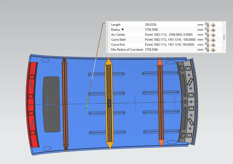
Rx (CTR & 2nd )
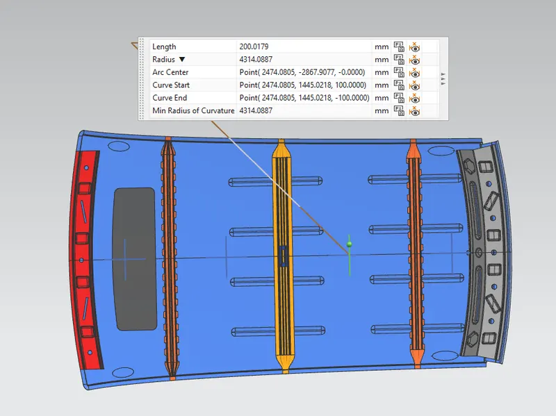
Rx (2nd & RR)
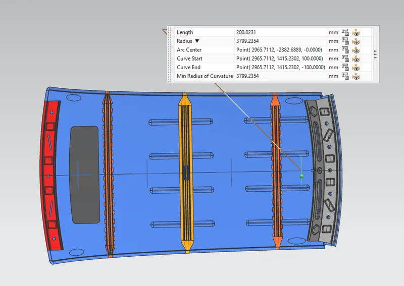
Ry (FR & 1st )
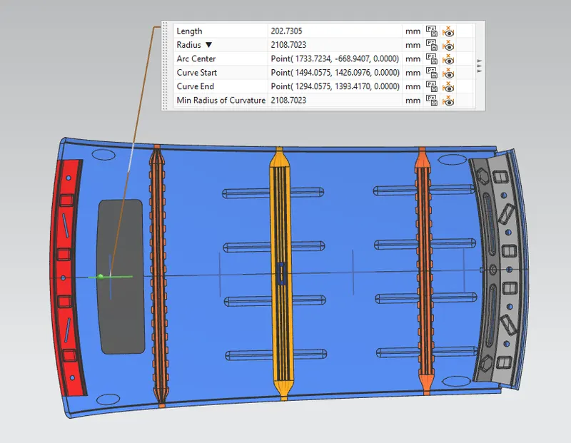
Ry ( 1st & CTR )
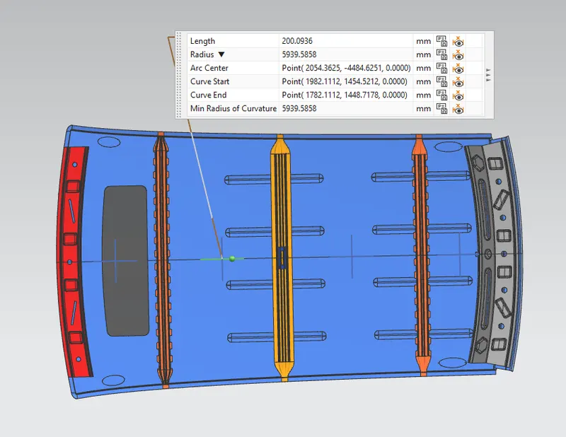
Ry (CTR & 2nd )
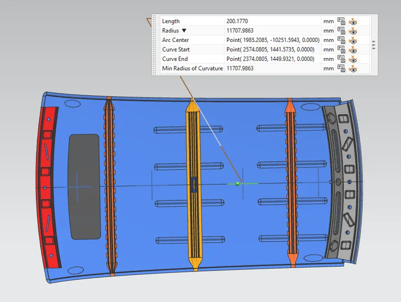
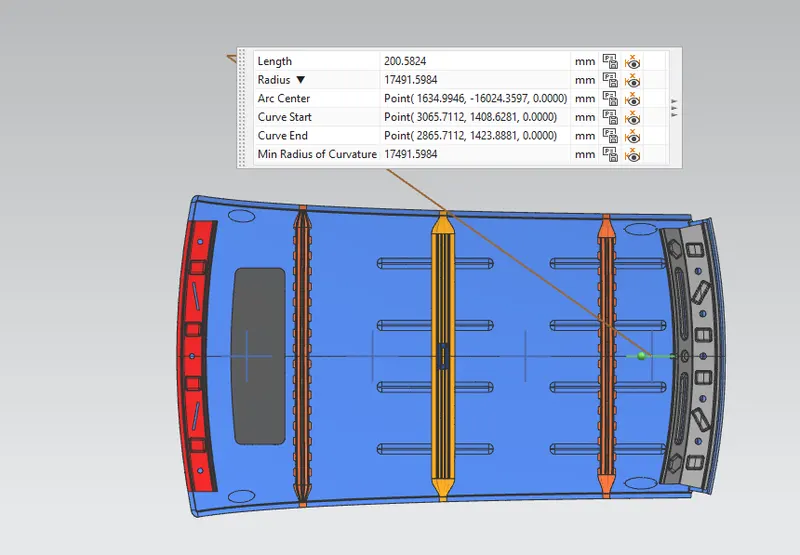
Ry ( 2nd & RR )
Procedure to calculate necessary parameters:
a) On plane parallel to the top plane draw sketch in which 0Y is projected along the direction perpendicular to top plane
b) Draw lines perpendicular to 0Y line passing through point exact midpoint of the two adjacent parts (e.g., midpoint between front rail and bow roof 1)
c) Offset these reference lines on both sides by 100 mm
d)Mark intersection points of reference line and 100 mm offset lines.
e) These reference points are then projected on to roof outer panel surface to create curves.
f) Take all necessary measurements required to calculate QR value as per mentioned formula.
Apply the values in the formula:
To find the Snow load calculation apply all the necessary values from the Roof to the given formula.
| SNOW LOAD CALCULATION | |||||||||||||
| S.NO | BOWs | ly | a | Lx | Ly | y | s | Rx | Ry | t | My | Qr | Determination |
| 1 | FR & 1st | 370.84 | 0.91912 | 1155.96 | 2034 | 428.4 | 489.7 | 4823.62 | 2108.7 | 0.75 | 687839.04 | 3.857 | Ok |
| 2 | 1st & CTR | 72.14 | 0.985569 | 1100.32 | 2034 | 547.7 | 591.96 | 3758.55 | 5939.58 | 0.75 | 814046.51 | 5.67 | OK |
| 3 | CTR & 2nd | 72.14 | 1.014456 | 1068.05 | 2034 | 636.23 | 492.52 | 4314.08 | 11707.98 | 0.75 | 889303.2 | 8.88 | OK |
| 4 | 2nd & RR | 0.650681 | 1054.27 | 2034 | 347.02 | 211.63 | 3799.23 | 17491.59 | 0.75 | 585415.79 | DIV/0 | DIV/0 | |
Judgment condition
Qr ≥ 3.1
250 ≤ s ≤ 380
All Values are under Judgement Condition.
Conclusion:
The Design of Roof, Front roof rail, Rear Roof Rail, Bow Roofs, and reinforcement roof center by following the Master section with the design parameter for the given class A surface is done.
- Using all input data we have successfully designed Ditch area flanges, Front roof rail, Bow roof rails, Rear roof rail as per the requirement.
- As per heat distortion criteria we come to know all bow roof positions are OK.
- As per Snow load criteria we come to know there is improvement required.
- All roof rails draft analysis are found OK.