Roof challenge
OBJECTIVE
A. Create an ASSEMBLY by developing the essential flanges for the outer roof and creating the reinforcements with help of given roof styling.
B. Provide appropriate dimensions and check for Draft analysis.
C. Do a curvature study on the roof and perform calculations to determine the position of the Bow-roofs.
INRTADUCTION
ROOF
An automobile roof or car top is the portion of an automobile that sits above the passenger compartment, protecting the vehicle occupants from sun, wind, rain, and other external elements.
Types of Roofs
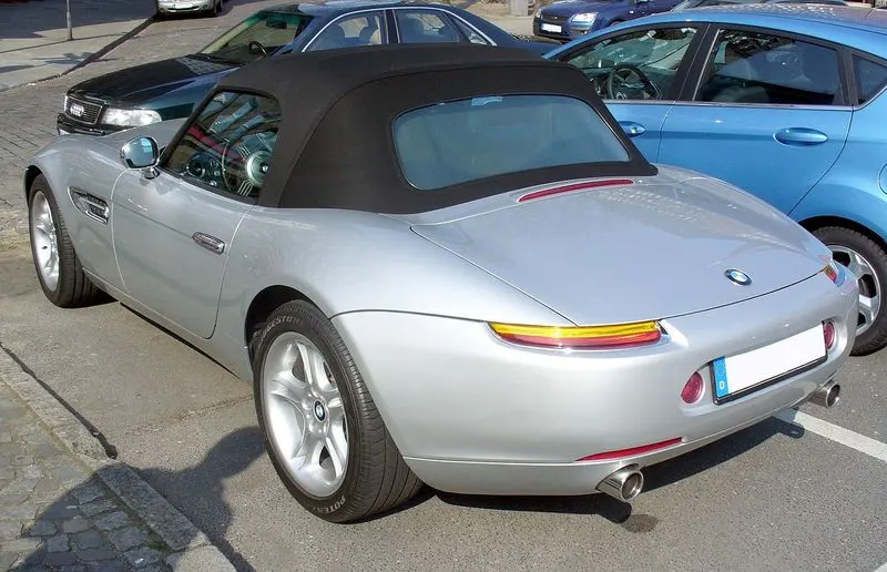
1. Convertible roofs
2. Hardtop roofs
3. Sunroofs
4. T-top
5. Targa tops
6. Vinyl roofs
1. Convertible roofs
- Early convertibles used cotton canvas woven so tightly that it is waterproof. However, automakers had problems in securing raw materials to fulfill orders after World War II, including canvas in various shades for convertible tops, therefore limiting their manufacture.
- A cloth-based material has become more common in recent years.
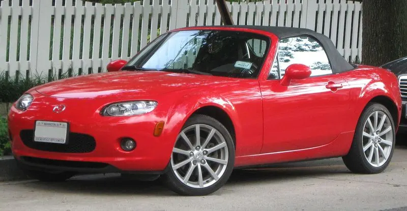
2. Hardtop roofs
A hardtop is a rigid form of automobile roof, which for modern cars is typically constructed from metal. A hardtop roof can be either fixed (i.e. not removable),detachable for separate storing or rectractable within the vehicle itself.
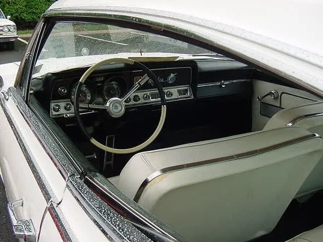
3. Sunroofs
A sunroof is a movable panel that opens to uncover a window in anautomobile roof, allowing light and fresh air to enter the passenger compartment. Sunroofs can be manually operated or motor driven, and are available in many shapes, sizes and styles. While the term "sunroof" is now used generically to describe any glass panel in the roof, the term "moonroof" was historically used to describe stationary glass panes rigidly mounted in the roof panel over the passenger compartment. A moonroof has a glass panel that is transparent and usually tinted. Previous terms include Sunshine Roof, Sliding Head and Sliding Roof.
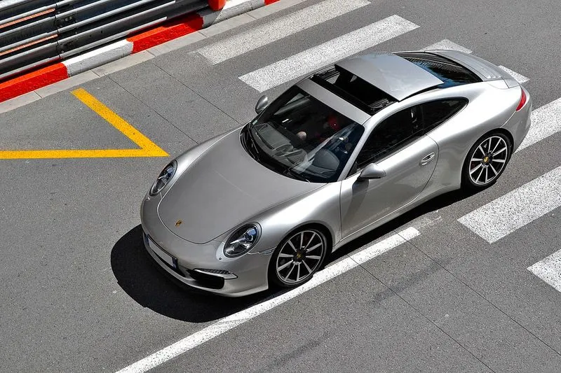
4. T-top
A T-top (UK: T-bar) is an automobile roof with a removable panel on each side of a rigid bar running from the center of one structural bar between pillars to the center of the next structural bar. The panels of a traditional T-top are usually made of auto grade safety glass.
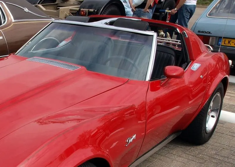
5. Targa tops
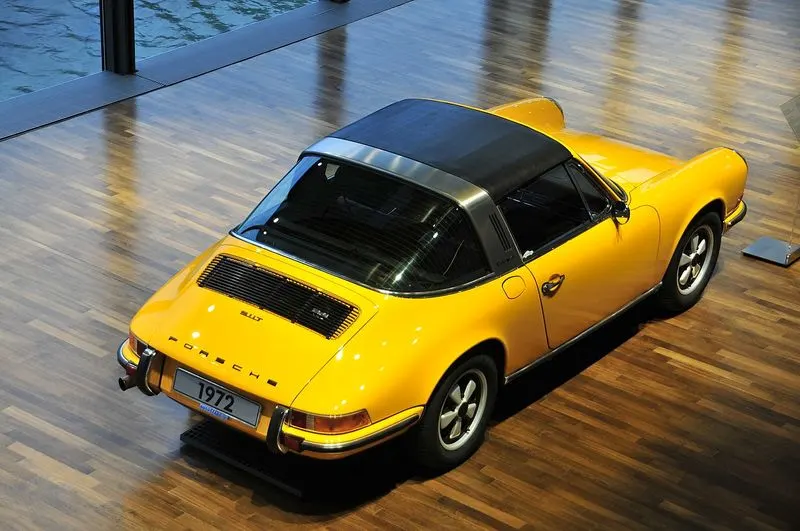
Targa top, or targa for short, is a semi Convertible car body style with a removable roof section and a full width roll bar behind the seats. The term was first used on the 1966 Porsche 911 Targa, and it remains a registered trademark ofPorsche AG.
6. Vinyl roofs
This covering was originally designed to give the appearance of a convertible to models with a fixed roof, but eventually it evolved into a styling statement in its own right. Vinyl roofs were most popular in the American market, and they are considered one of the period hallmarks of 1970s Detroit cars. Vinyl roofs were also popular on European- (especially UK-) and Japanese-built cars during the 1970s, and tended to be applied to sporting or luxury trim versions of standard saloon (sedan) models.
ROOF STRUCTURE
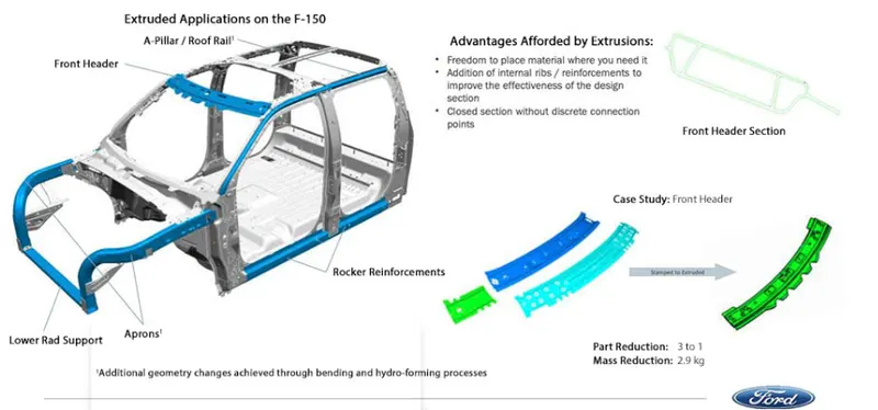
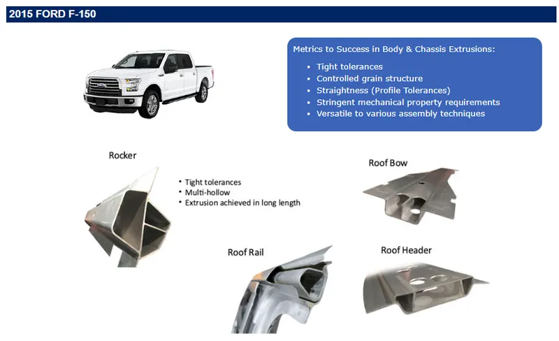
A roof structure for a vehicle body includes a roof opening defined by a pair of spaced apart side rails, each having a flange extending inwardly and being vertically offset below the roof surface, and by front and rear headers, each having a flange defining a window opening. A roof panel assembly includes a roof outer panel and a pair of inverted hat-shaped reinforcement rails which underlie the outer side edges of the roof outer panel and include inwardly and outwardly directed legs abutting the underside of the roof outer panel. The outermost portion of the side edges of the roof outer panel are hem flanged over the outwardly directed flanges of the reinforcement rails so that the roof outer panel and the reinforcement rails define the roof panel assembly. The roof outer panel has fore and aft end flanges which overlie the flanges of the front and rear headers and are spot welded thereto. A bead of adhesive is placed on the inwardly extending flanges of the side rails and the roof panel assembly is lowered into the roof opening with the base wall of the reinforcement rails pressed onto the adhesive to attach the roof panel assembly to the vehicle body. The subsequent installation of the front and rear windows hides the spot welds.
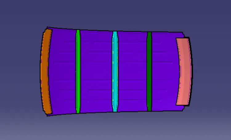
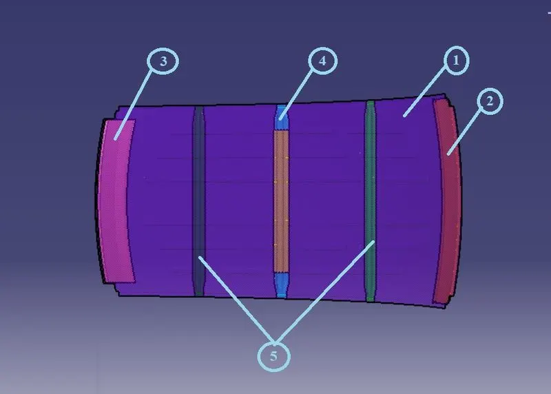
There are different rail reinforcements in a roof panel like:
1. Roof Outer Pannel
2. Front Roof Rail
3. Rear Roof Rail
4.Center Roof Rail and Reinforcement
5. Bow Roof Rails
SOFTWARE : CATIA V5
A. Create an ASSEMBLY by developing the essential flanges for the outer roof and creating the reinforcements with help of given roof styling.
Given Roof Styling Suface
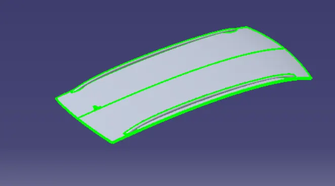
DESIGN PROCEDURE
Create a Roof Assembly product and ADD create new part or existing parts
1.ROOF OUTER PANEL with Ditch Area
Surfaces were extracted from the given styling data.
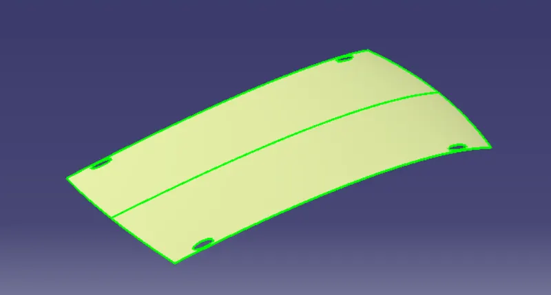
Untrimmed to get the original surface back.
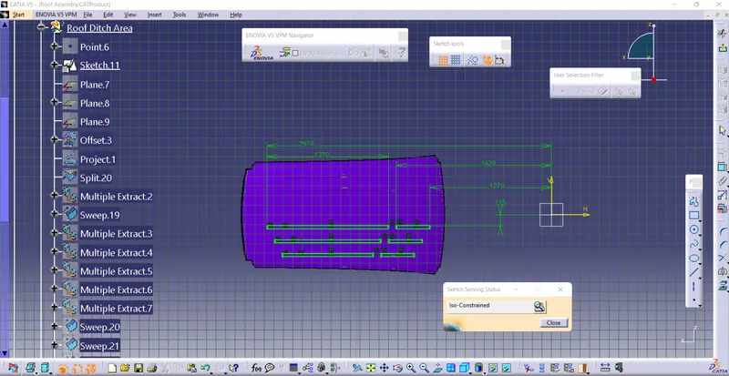
Create Ditch Area sketch ISO- Constrained
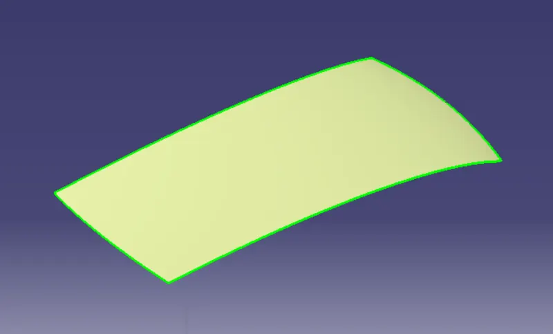
Symmentry ditch area surface
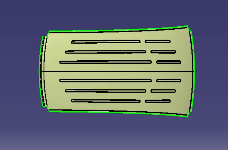
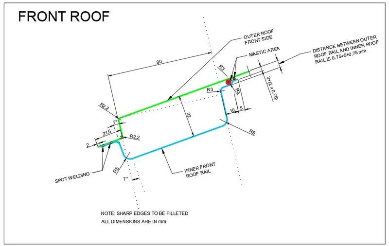
Create Roof Outer panel Front,Side and Rear posion with help of given master sections
Front Roof Rail Master section
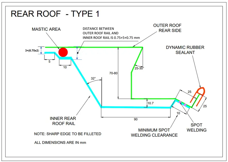
Master section of the Rear Roof Rail
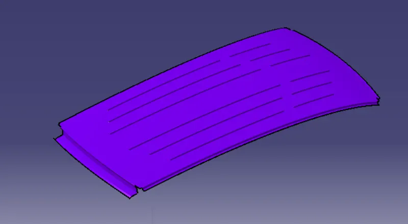
Final Roof outer panel thick surface of Part body
2. FRONT ROOF RAIL :
Front roof rail is used to provide strength to the roof panel front and it also acts as link between windshield glass, roof panel and headliner(interior trim). Headroom clearance and visibility are two important criteria for the driver and both of them depends upon the front roof rail dimensions, hence it is important to select appropriate dimensions for the roof rail.
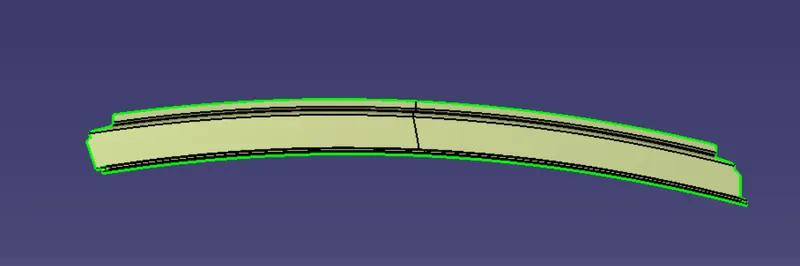
Create Front Roof Rail using above front roof rail master section
Surfaces were extracted from the above Roof Outer panel
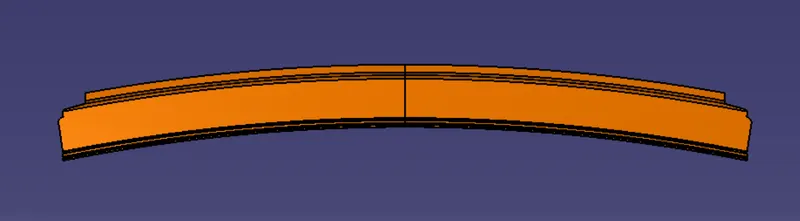
Final Front Roof Rail thicksurface of Part body
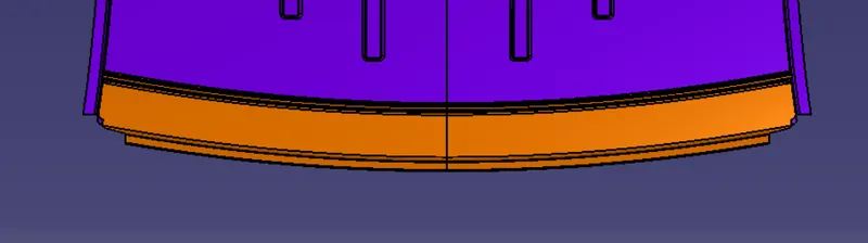
Assembly views as for given master section
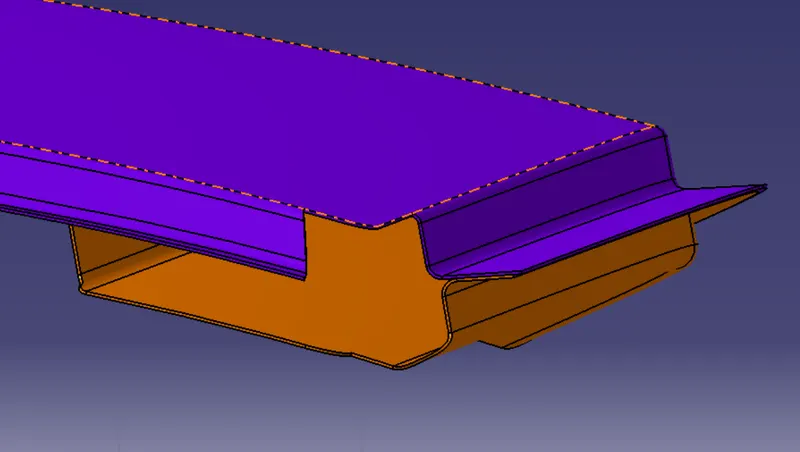
3. REAR ROOF RAIL :
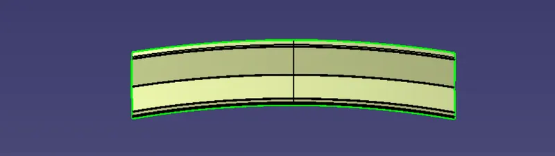
Final Rear Roof Rail thicksurface of Part body
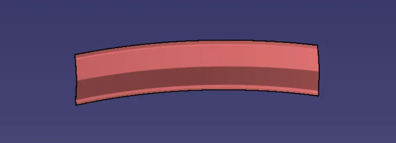
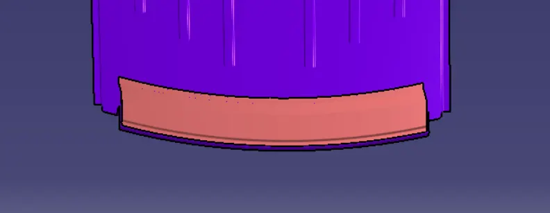
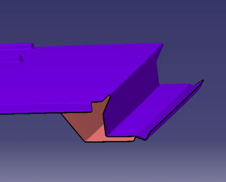
4. Center Roof Rail and Reinforcement
Master section of Center Reinforcement Rail
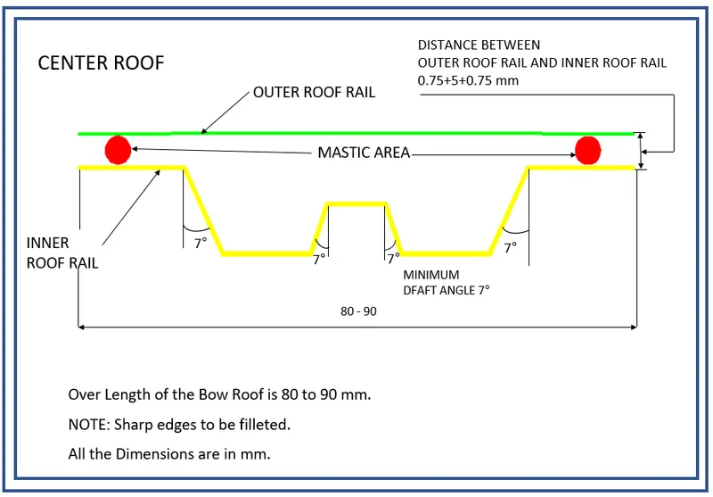
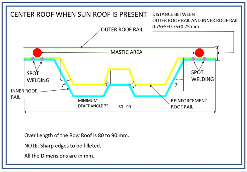
Center Roof Rail
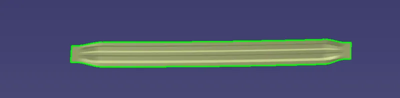
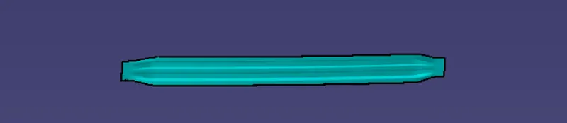
Center Reinforcement Rail
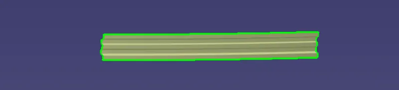
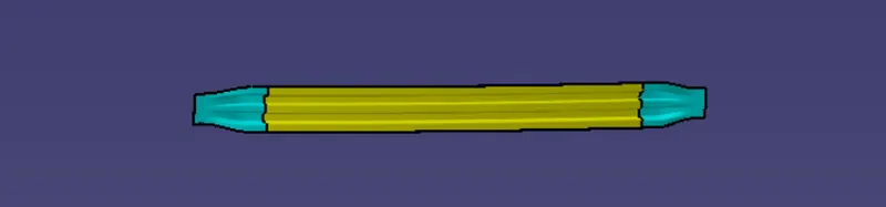

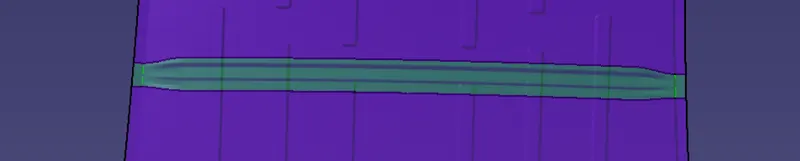
5. Bow Roof Rails 1 and 2 :
Master section of Bow Roof
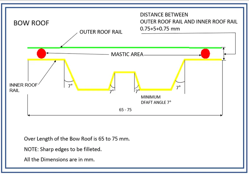
Bow Roof Rails 1


Bow Roof Rails 2



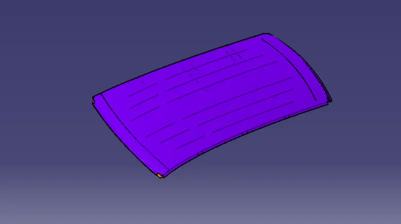
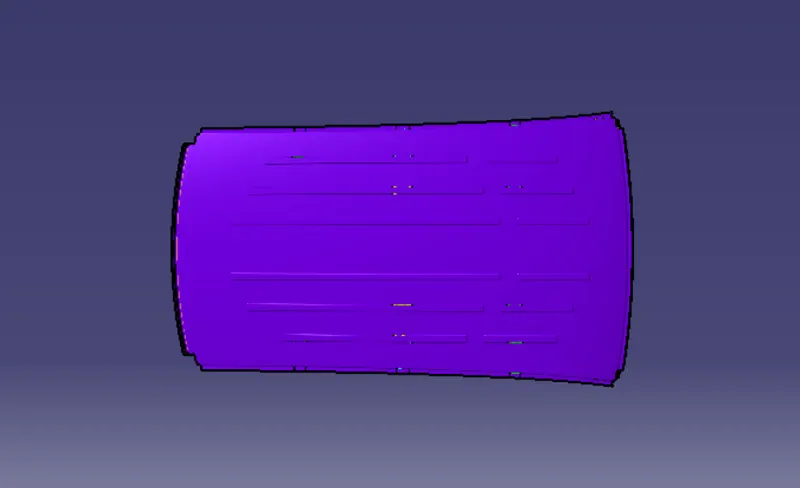
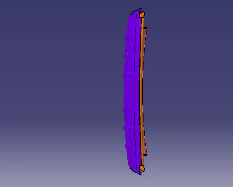
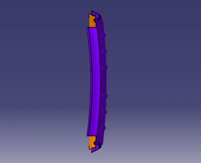
Different Assembly View
B. Provide appropriate dimensions and check for Draft analysis.
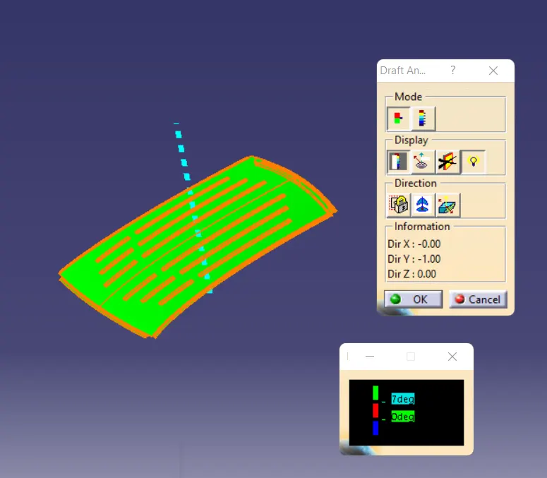
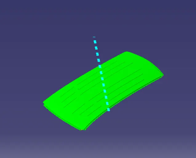
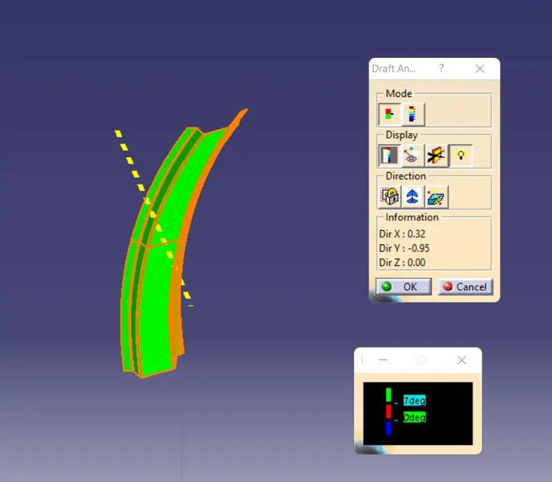
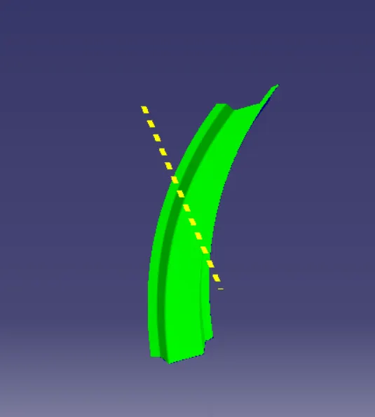
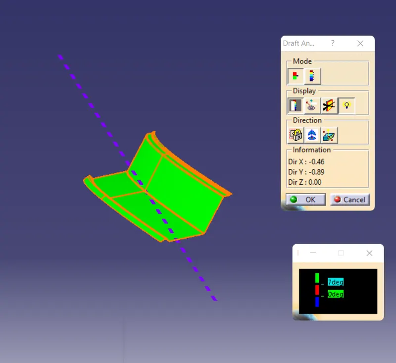
It is important that what-ever is designed should be easily manufactured. Draft analysis only is not a sure shot confirmation that the cad design is 100 % manufacturable but it checks that all the surfaces are greater than or equal to a particular angle (in sheet-metal it is 7 degrees).
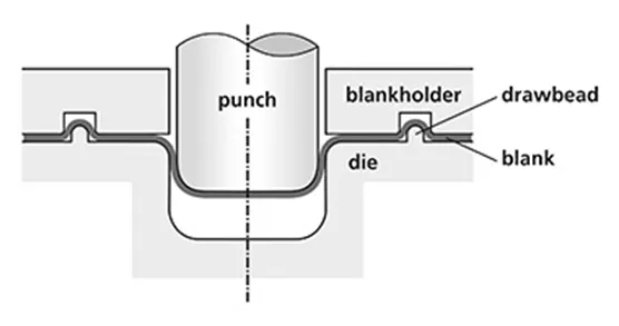
Drawing / Stamping Direction :
A sheet metal part is manufactured by the stamping process. In this process a punch and die are used to generate the desired shape. The stamping direction indicates the direction in which the punch moves.
1. Roof Outer Panel :
2. Front Roof Rail :
3. Rear Roof Rail :
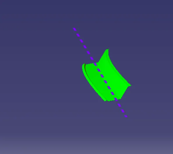
4. Center Roof Rail :
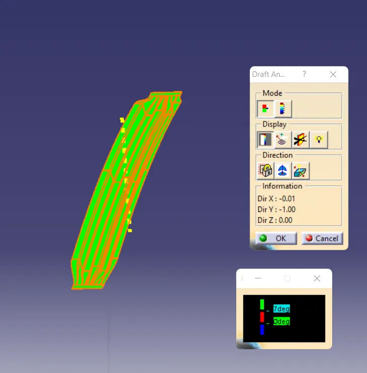
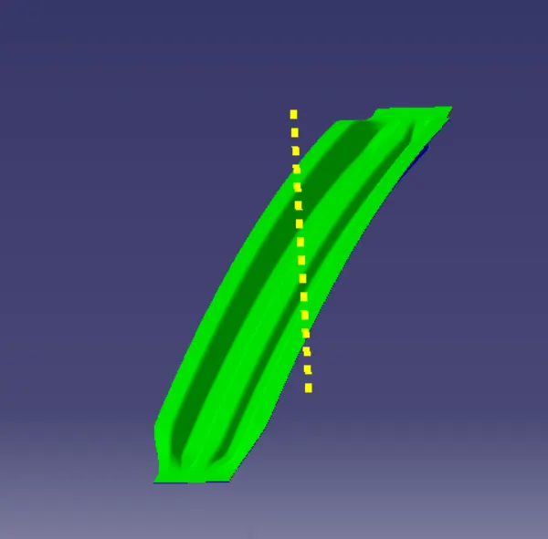
5. Reinforcement Roof Rail :
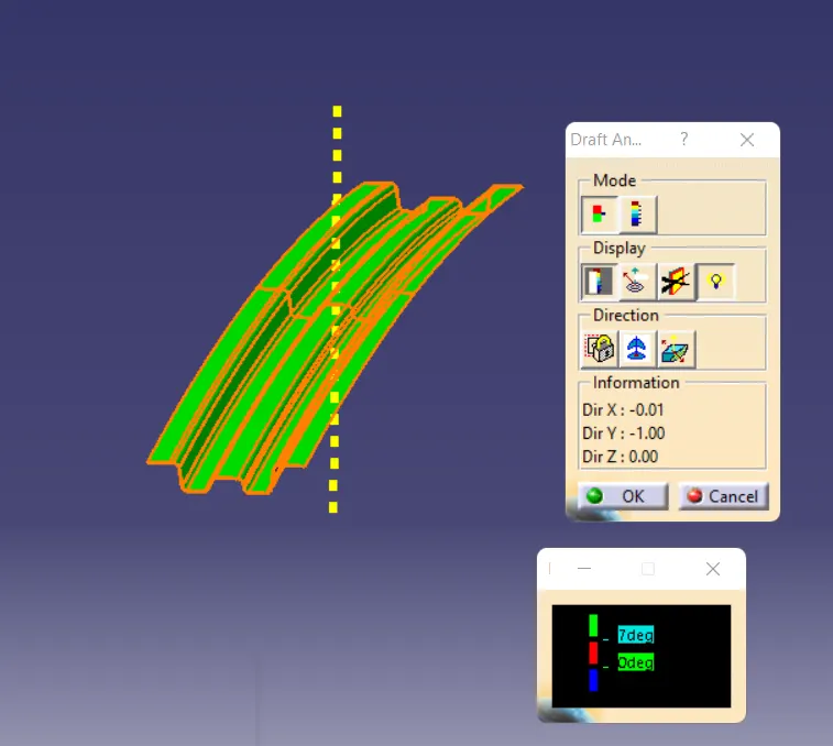
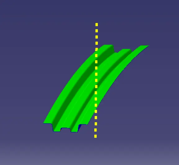
6. Bow Roof Rail 1 :
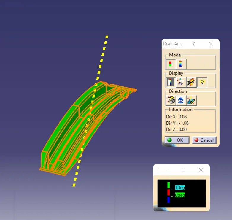
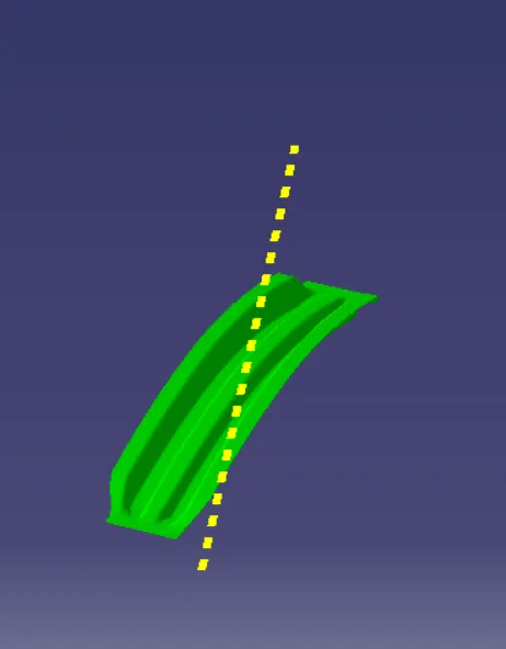
7. Bow Roof Rail 2 :
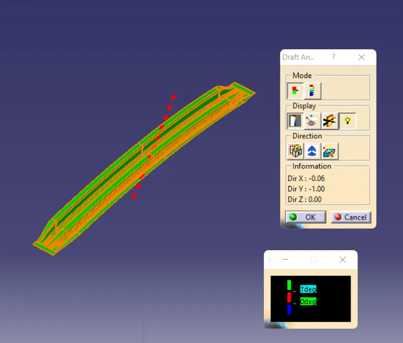
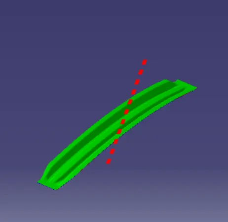
C. Do a curvature study on the roof and perform calculations to determine the position of the Bow-roofs.
Before sending the CAD models to the simulation team it is important to justify the position of the bow roof and their bow span. It actually leads to the prevention of most of the problems that may occur in the design stage. There are two ways in which we can perform this study Before performing the study we ourselves analyse the roof curvature.
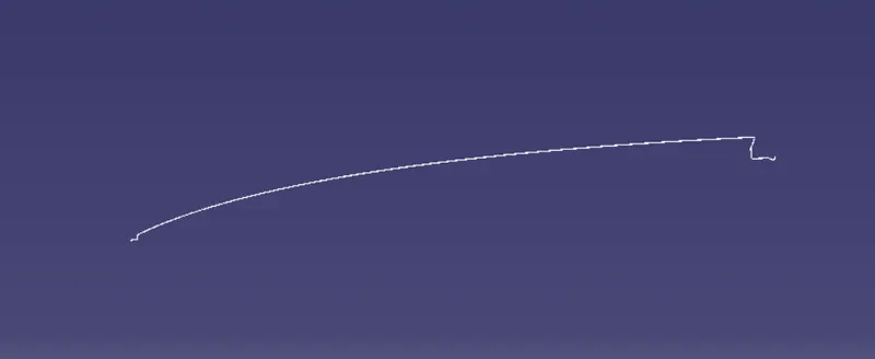
Above is an image of the cross section of the roof panel, as we can see that the front portion(from the left) has more curvature as compared to the rear half(to the right) we can place the bow roofs in such a way that more strength is given to the rear half. For this I have proposed the following design
1. Bow–Roof Prediction Formula :
W = [1.73 x 10^(-3) x L] + [1.85 x 10^(-8) x (R^2)/t] + [ 1.10x10^(-3) x l] - 2.68
Where,
L = Roof Length in X-Direction[mm](Roof dimension in 0-Y)
R = Roof curvature
R = 2(Rx*Ry)/(Rx+Ry)
Rx = X curvature
Ry = Y curvature
t = Roof plate thickness [mm]
l = Bow Roof Span [mm]
Measure "L" value roof length in X- Direction
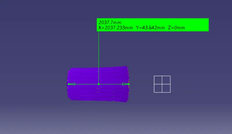
L = 2037.7 mm
t = Roof plate thickness [mm]
t = 0.75 mm
Calculate the Rx ,Ry values
Create sketch
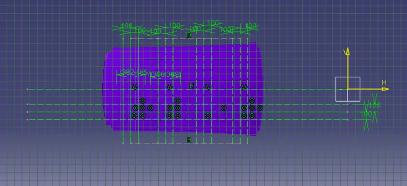
Create three point curve
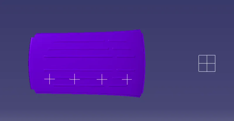
Measure the Rx ,Ry values
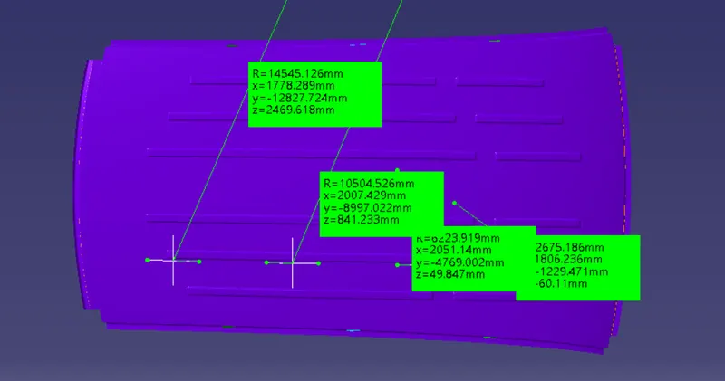
Rx = X curvature
Rx values conditions 1
Rx1 = 2675.186 mm
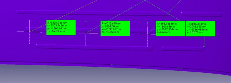
Ry = Y curvature
Ry Values conditions 1
Ry1 = 5816.434 mm
Calculate "R" value using formula
R = Roof curvature
R = 2(Rx*Ry)/(Rx+Ry)
R values conditions 1
R1 = 3664.799 mm
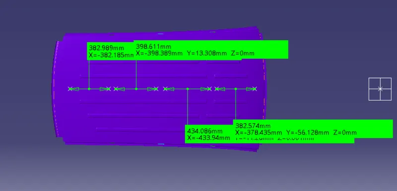
I = Bow Roof Span [mm] values conditions 1
I1 = 382.574 mm
Bow–Roof Prediction Formula,
W = [1.73 x 10^(-3) x L] + [1.85 x 10^(-8) x (R^2)/t] + [ 1.10x10^(-3) x l] - 2.68
| Condition | L | I | t | RX | RY | R | W |
| 1 | 2037.7 | 382.574 | 0.75 | 2675.186 | 5816.434 | 3664.799 | 1.592264935 |
| 2 | 2037.7 | 434.086 | 0.75 | 6223.919 | 4982.488 | 5534.441 | 2.077568391 |
| 3 | 2037.7 | 398.611 | 0.75 | 10504.526 | 4015.679 | 5810.221 | 2.115635238 |
| 4 | 2037.7 | 382.989 | 0.75 | 14545.126 | 3334.746 | 5425.575 | 1.991206388 |
Judgment Condition
OK< 2.7
Here we got the w values less than 2.7 the judgement condition is ok
2. Snow Load Prediction Formula :
Qr = [Iy x t2] / [α x s x [(Rx + Ry)/2]2 x 10-8]
Where,
α = My x Lx2 x 10-12 , My = Y(Ly-Y)
t = Roof plate thickness [mm]
Ly = Distance between the front and rear roof Rails on the Vehicle along with 0Y[mm]
Length of Roof panel with the center point between Roof rail Front /Rear as the front and rear reference point.
Lx = Distance between the Left and Right end of the roof on the Roof BOW [mm]
The width of the roof panel is exposed on the surface.
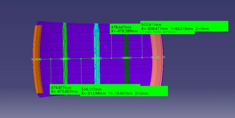
Y = Distance front Front Roof Rail to Roof BOW[mm]
s = Distance for which Roof BOW bears divided load [mm
s = L1/2 + L2/2
Iy = Geometrical moment of inertia of Roof BOW (Y cross-section )[mm4]
Rx = Lateral direction curvature radius of roof panel Y cross-section on Roof BOW [mm]
Roof panel curvature Radius of the Length Lx in Front view
Ry = Longitudinal Direction curvature radius of the Roof panel X cross-section on Roof BOW [mm]
Roof panel X curvature radius of length s in Side view
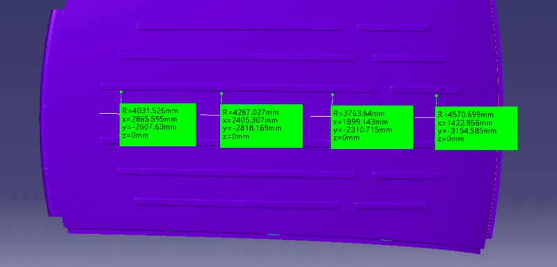
Measure " Rx ", "Ry" values roof assembly
Create sketch
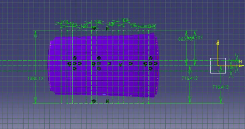
Project the sketch on surface
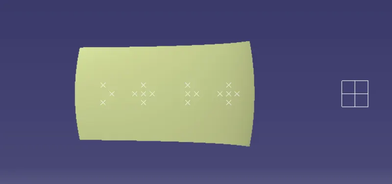
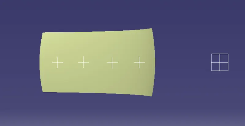
Create three point curve
Measure " Rx ",
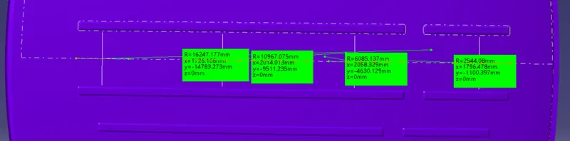
Measure " Ry ",
Measure "Y" and " L1 ", "L2" values roof assembly
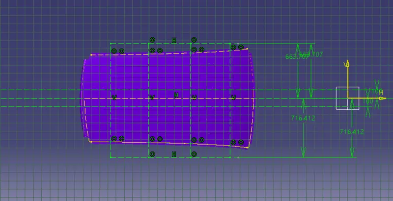
Measure "Lx" and "Ly" values roof assembly
Ly = Distance between the front and rear roof Rails on the Vehicle along with 0Y[mm]
Length of Roof panel with the center point between Roof rail Front /Rear as the front and rear reference point.
Lx = Distance between the Left and Right end of the roof on the Roof BOW [mm]
The width of the roof panel is exposed on the surface.
Create sketch
Project the sketch on surface
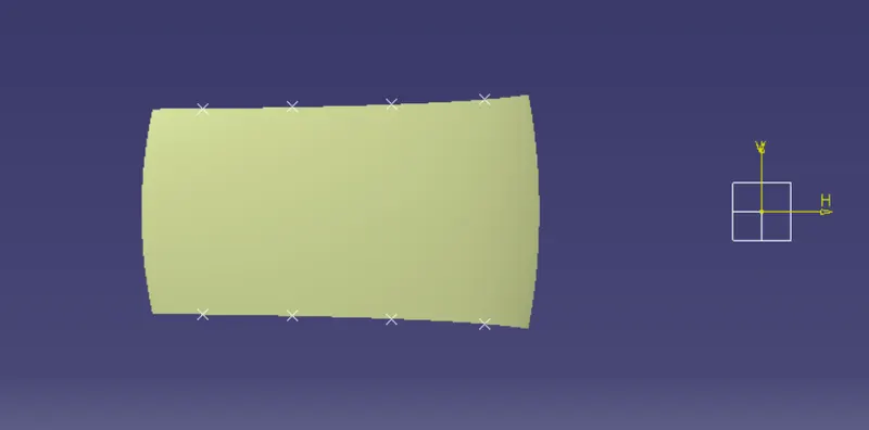
Measure "Lx"
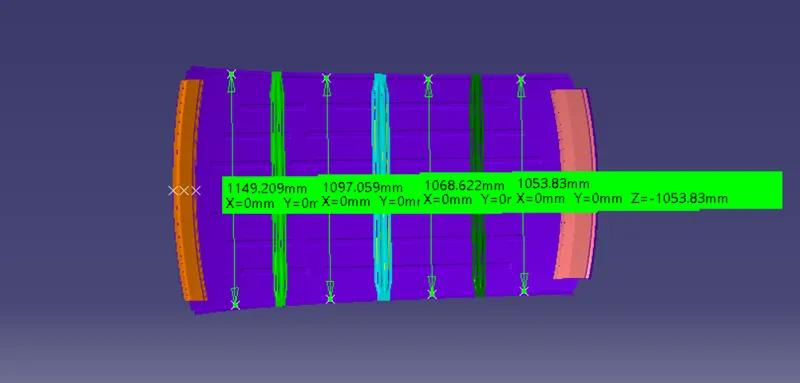
Measure "Ly"
Iy = Geometrical moment of inertia of Roof BOW (Y cross-section )[mm4]
1. Calculate moment of inertia of BOW ROOF 1
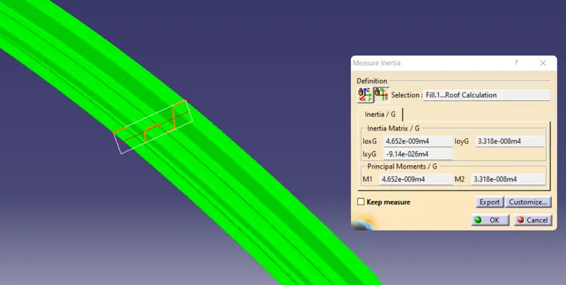
moment of inertia condition 1,
Iy1 = 4.652 × 10^-9× m^4
= 4.562 × 10^-9 × (10^3)^4mm^4
= 4562 mm^4
2. Calculate moment of inertia of CENTER ROOF
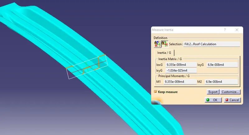
moment of inertia condition 2,
Iy2 = 9.335 × 10^-9× m^4
= 9.335 × 10^-9 × (10^3)^4mm^4
= 9335 mm^4
3. Calculate moment of inertia of BOW ROOF 2
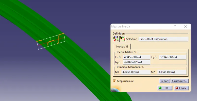
moment of inertia condition 2,
Iy2 = 4.345 × 10^-9× m^4
= 4.345 × 10^-9 × (10^3)^4mm^4
= 4345 mm^4
Judgment condition
Qr ≥ 3.1
250 ≤ s ≤ 380
Snow Load Prediction Formula,
Qr = [Iy x t2] / [α x s x [(Rx + Ry)/2]2 x 10-8]
| Condition | Iy | t | Y | Lx | Ly | My | α | L1 | L2 | S | Rx | Ry | Qr |
| 1 | 4652 | 0.75 | 476.877 | 1149.209 | 2037.7 | 744320.5898 | 0.9830103032 | 476.877 | 514.117 | 495.497 | 2544.08 | 4570.699 | 42.45220922 |
| 2 | 9335 | 0.75 | 514.117 | 1097.059 | 2037.7 | 783299.9212 | 0.9427315727 | 514.117 | 478.647 | 496.382 | 6085.137 | 3763.64 | 46.27305313 |
| 3 | 4345 | 0.75 | 478.647 | 1068.622 | 2037.7 | 746236.0413 | 0.8521664703 | 478.647 | 512.611 | 495.629 | 10967.075 | 4267.027 | 9.973725902 |
Here we got the Qr values greater than 3.1 but as you can see the s value is greater than 380mm because only two bow roof created if add more bow roof get judgement position values or ok and more strength to the roof.
Conclusion :
Roof panel with all the necessary reinforcements have been created, Draft Analysis, Bow Roof and Snow Load Prediction justification has been provided with help of master section and prediction formulas.