Roof Design
Objective:-
To a given roof styling, create essential flanges and reinforcements.
Introduction:-
An automobile roof is the top portion of an automobile that sits above the passenger compartment, protecting the vehicle occupants from sun, wind, rain & other external elements. Automotive roof plays an important role in aerodynamics & internal strength of vehicle. The roof’s BIW influences the aftermath effects of crush load, snow load and heat distortion criteria. The roof has internal structures like front roof rail, rear roof rail, bow roof 1, bow roof 2 and reinforcement roof rail. But some places of roof have flatness compared to other section, mostly while approaching the trailing edge of roof the roof becomes flat relatively. Sometimes this flatness is intentionally given to reduce the creation of a wake region while moving faster. The roof is like building a house. The house needs pillars, similarly the roof needs the internal structure to ensure safety and performance. The roof has to perform good in roll over test. The outer panel of roof is considered as class a surface, so there cannot be any spot welds or any visible fastening. Mastics plays major role in engaging the roof panel and the internal BIW parts.
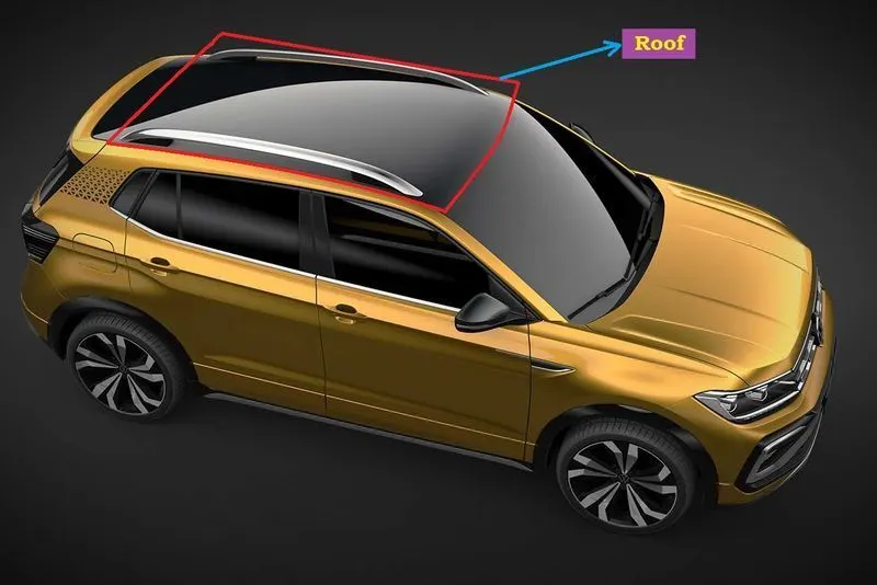
The roof is a styling surface part which is fixed with the BIW body through the rails and panels inside the upper roof to provide it strength and stiffness.
Types of car roofs:
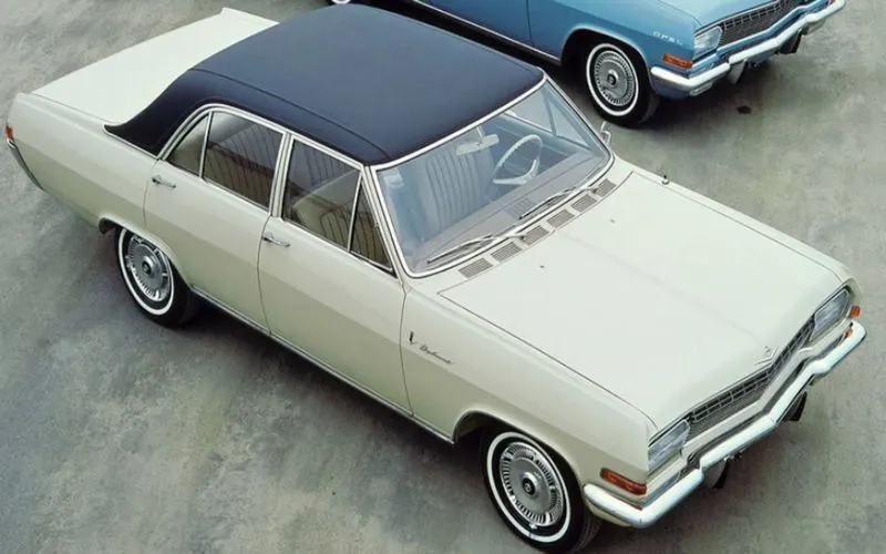
1. Hardtop Roofs

2. Convertible Roofs

3. SunRoofs
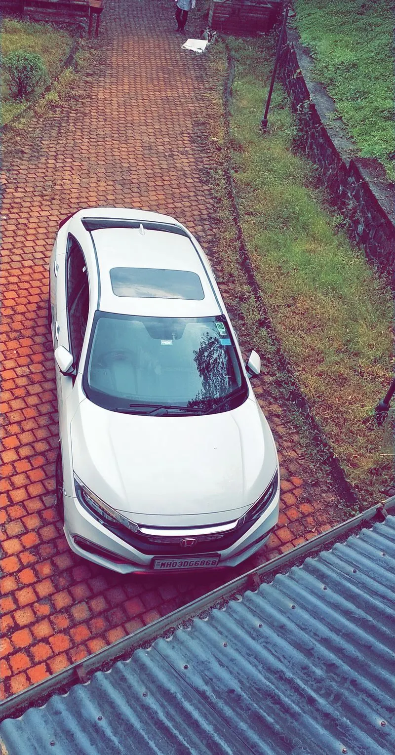
4. T-top Roofs
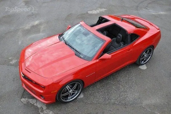
5. Targa Top Roofs
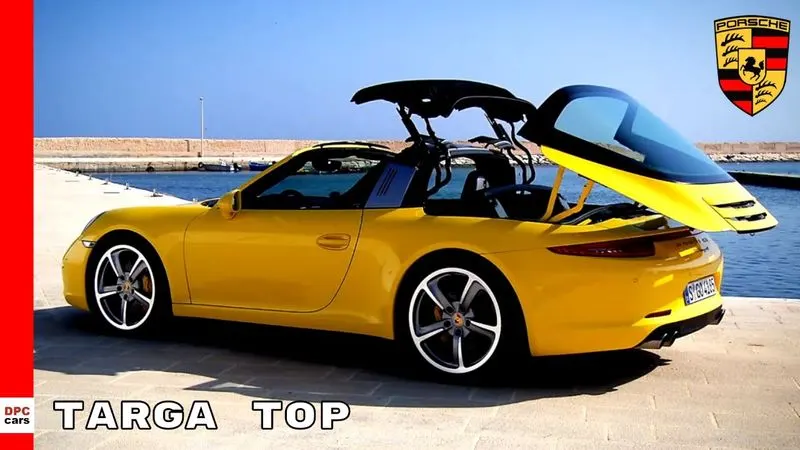
6.Vinyl Roofs
Roof Crush Test:
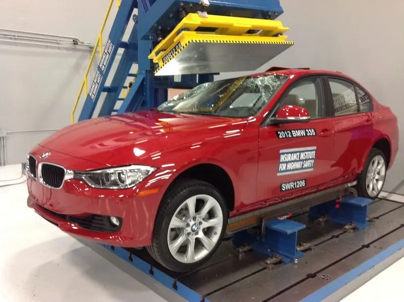
Passenger safety is a very important parameter in front of OEMs. For this reason, strength is a very important criteria for designing a vehicle roof. The strength of the roof structure to occupant the protection in real world crashes, requiring the maximum moving distance of the roof structure should be less than 127mm when the induced load is 1.5 times the vehicle weight. For the test, the passenger car shall be rigidly placed or positioned on horizontal surface with the doors locked and the window closed. This test can be conducted on either side of the roof structure, the front left or front right side but not on both sides in one single test and still meet the requirements of the test.
Rollover accidents of a car are the most occurring accidents that we see in our daily lives. The passengers experience major injuries like neck, head and spine injuries. So, to reduce the injuries of a passenger from major fatalities it is important to provide safety in the car. Though safety is provided by seat belts and airbags during accidents, the passenger must have sufficient space for survival in the car during accidents. The roof of the car must have high strength to resist the crush force to avail the passenger some space for survival.
Reinforcements :-
If the roof is flat it is very weak and cannot able to withstand the forces like snow, so in order to increase the strength of the roof these reinforcements like front roof rail, central roof rail, rear roof rail & the bow roofs are introduced & joined to the flat surface of the roof with the different joining process.
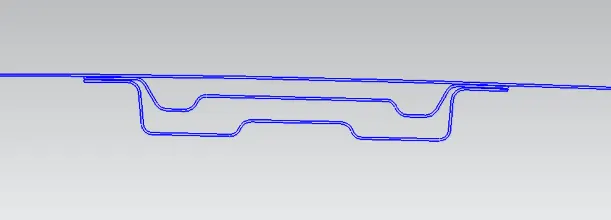
Front roof rail :-
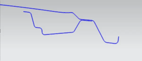
Front roof rail is the one which joins the wind shield glass, body side outer & the inner panel.
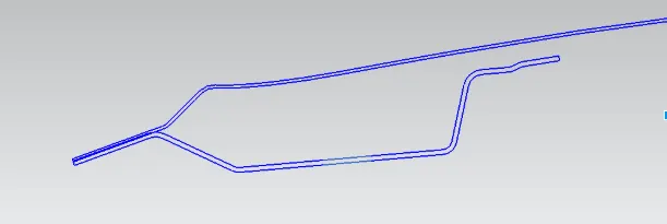
Rear roof rail :-
Rear roof rail is the one which joins the back door and the body side outer.
Bow roofs :-
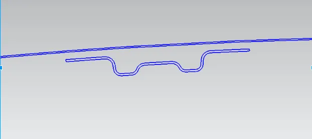
The bow roofs are given to improve the torsional stiffness and load bearing capacity of the roof structure. The number of bow roof present is depends on the overall size of the roof.
Structure of the Roof :-
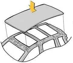
Apart from aerodynamic shape of roof it has to withstand the induced drag force on surfaces. To make the roof more structurally rigid and to improve its local strength the BIW parts designed. These structures also facilitates for cabin amenities like lighting and some other electrical electronic instruments.
Process of Joining :- Mastics are introduced between the roof outer panel and the reinforcements for joining. where ever the mastic are introduced there is remarkable improve of the strength. Spot welding is also introduced to join the reinforcements and the outer panel. In the bow roof I section the top flanges are joined with the outer panel of roof with the help of mastic sealants whereas the bottom flanges are joined with the assembly using spot welds. These individual sections can be produced by simple bending operations. The individual section of I can be joined by either seam welding along the web of I section or by spot welding acording to the manufacturing flexibility. After joining web sections the I section is joined with the bottom flange using spot welds to make as one unit of assembly.
Heat Distortion Criteria :-
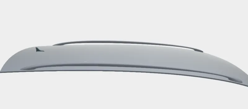
Heat Distortion is the temperature at which the metal softens and deforms under a specific load. This study is done to check the ability of the roof to withstand high temperature with respect to the positioning of the reinforcements which contributes to increase the strength.
Bow roof prediction formula
W = [1.73 x 10^(-3) x L] + [1.85 x 10^(-8) x (R^2)/t] + [ 1.10x10^(-3) x l] - 2.68
Judgement Condition : OK< 2.7> 3.1
Where
L = Roof Length in X-Direction[mm](Roof dimension in 0-Y)
R = Roof curvature
R = 2(Rx*Ry)/(Rx+Ry)
Rx = X curvature
Ry = Y curvature
t = Roof plate thickness [mm]
l = Bow Roof Span [mm]
CALCULATION TABLE:
|
Position |
RX |
RY |
L |
t |
l |
W |
Prediction |
|
FR-BR1 |
2614.80 |
5733.94 |
1918 |
0.75 |
502.96 |
1.51 |
OK |
|
BR1-CR |
3581.59 |
5102.60 |
1918 |
0.75 |
331.73 |
1.43 |
OK |
|
CR- BR2 |
8440.34 |
4424.81 |
1918 |
0.75 |
331.83 |
1.83 |
OK |
|
BR2-BR3 |
11512.32 |
3788.35 |
1918 |
0.75 |
377.71 |
1.85 |
OK |
|
BR3-RR |
14886.02 |
3234.45 |
1918 |
0.75 |
494.45 |
2.14 |
OK |
Snow Load Criteria :-
Snow Load Criteria study is done to check the withstand ability when the snow loads over the roof during winter in snow fall regions. This study will also analyze the roof that whether the permanent deformation occurs after removing the snow load, that it may bend but needs to be bounce back to its original position.
snow load prediction formula
Qr = [Iy x t2] / [α x s x [(Rx + Ry)/2]2 x 10-8]
Where
α = My x Lx2 x 10-12 , My = Y(Ly-Y)
Judgement condition = Qr ≥ 3.1
250 ≤ s ≤ 380
t = Roof plate thickness [mm]
Ly = Distance between the front and rear roof Rails on the Vehicle along with 0Y[mm]
Length of Roof panel with the center point between Roof rail Front /Rear as the reference point of the front and the rear.
Lx = Distance between the Left and Right end of the roof on the Roof BOW [mm]
Width of the roof panel exposed on the surface.
Y = Distance front Front Roof Rail to Roof BOW[mm]
s = Distance for which Roof BOW bears divided load [mm]
s = L1/2 + L2/2
Iy = Geometrical moment of inertia of Roof BOW (Y cross-section )[mm4]
Rx = Lateral direction curvature radius of roof panel Y cross-section on Roof BOW [mm]
Roof panel curvature Radius of the Length Lx in Front view
Ry = Longitudinal Direction curvature radius of the Roof panel X cross-section on Roof BOW [mm]
Roof panel X curvature radius of length s in Side view
CALCULATION TABLE:
| Sr. No. | Bow | Iy | α | Lx | Ly | y | s | Rx | Ry | t | Qr |
| 1 | Front rail to Bow 1 | 6251.35 | 0.87 | 1110.68 | 1923.11 | 496.938 | 502.695 | 4489.518 | 2673.741 | 0.75 | 62.68 |
| 2 | Bow 1 To Bow 2 | 6448 | 0.83 | 1072.662 | 1923.11 | 510.452 | 510.53 | 3774.198 | 833.065 | 0.75 | 14.098 |
| 3 | Bow 2 to Bow 3 | 6249 | 0.31 | 1052.201 | 1923.11 | 510.605 | 454.71 | 4289.698 | 1129+3.786 | 0.75 | 24.68 |
| 4 | Bow 3 to Rear rail | 1923.11 | 398.82 | 4064.855 | 16054.301 | 0.75 |
Conclusion :-
For the Given Roof styling, the essential flanges and reinforcements were developed & checked for analysis. The curvature study & the section modulus on the roof was carried out to determine the position of the Bow-roof Heat Distortion and Snow Load Criteria calculations. Thus the BIW roof of a car was designed for a better result.