Roof challenge
Roof Design
Aim: - Design a roof using the provided skin data and also calculated the heat distortion and snow calculation.
INDRODUCTION
An automobile roof or car top is the portion of an automobile that sits above the passenger compartment, protecting the vehicle occupants from sun, wind, rain, and other external elements. Because the earliest automobiles were designed in an era of house-drawn carriages, early automobile roof used similar material and design.
Roof is a styling surface part which is fixed with the BIW body through the rails and panels inside the upper roof to provide it strength and stiffness.
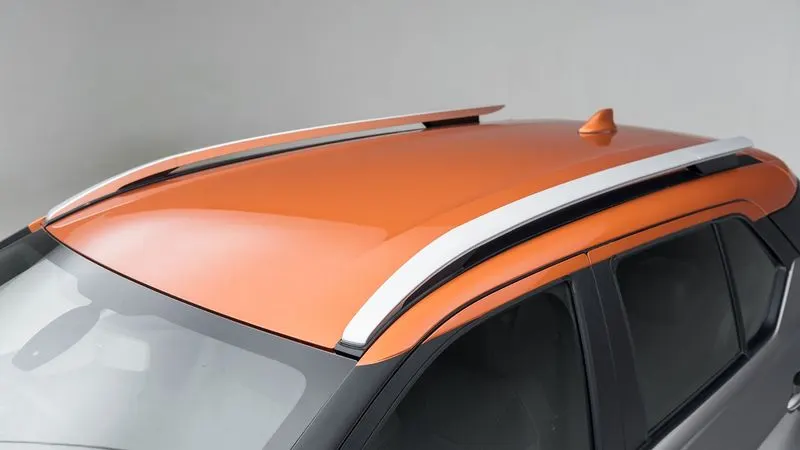
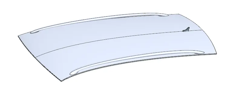
The rails and reinforcement are joined to the ditch area with a spot weld where it’s not the styling part.
The required tool opening angle is minimum 3 Degrees.
Factors which are considered before creating the Roof
- Headroom Clearance
- Visibility Criteria
- Back door Assembly
- Wind shield Assembly
Common Roof Part
- Front Rail
- Bow1
- Center Bow
- Bow2
- Rear Rail
Quantity of Bow depend on the length of the roof and analysis when the roof length is more then the Bow quantity is increase.
Front Roof Rail
Front Roof rail designed based up on the master section given. Front roof rail is the one which joins the wind shield glass, body side outer and inner panel.
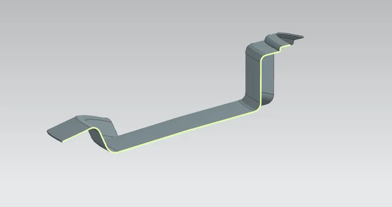
Bow 1
BOW 1 is an additional roof member used in the roof assembly for increase the strength of the roof. It is joined directly to roof with the mastic sealant. Creating the Bow 1 then min. draft angle is 7 deg. required.
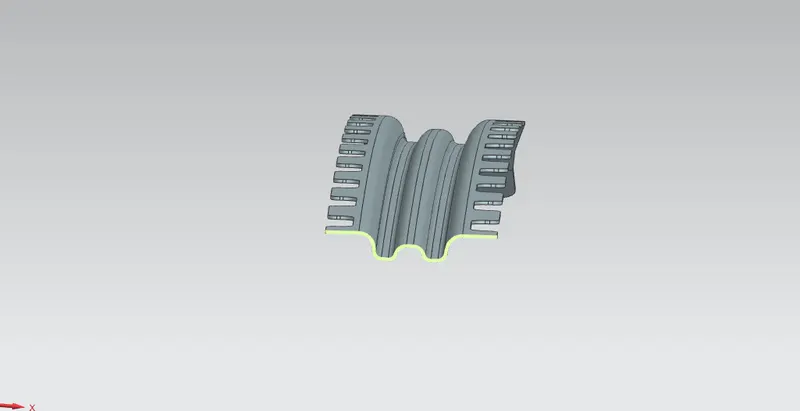
Center Roof Rail
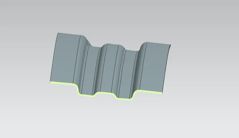
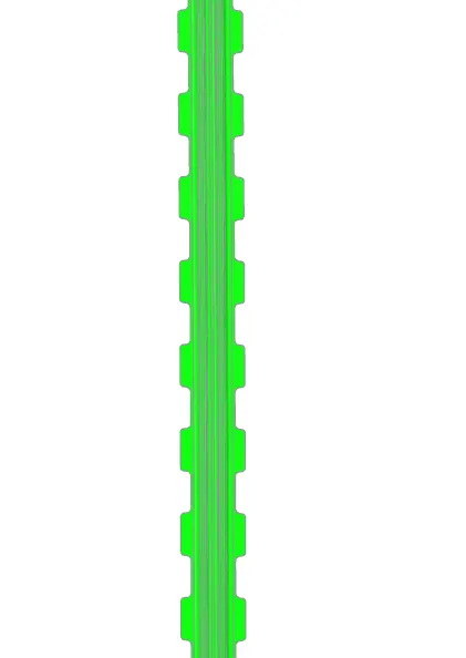
Center roof rail helps in providing support to the flat area of the roof as it is more susceptible to failure under the action of load. Generally center roof rail is placed at the center of the roof which is connected to the B-pillar support structure. Center roof rail helps in adding the strength to the roof during the roll-over test. Creating the center roof rail then min. draft angle is 7 deg. required.
In the Center roof rail, used the reinforcement also. Reinforcement is giving the more strength of the roof and center roof rail. Center roof rail is used in center of the roof and this area is flat area as compare to the other area so in this area required the more strength and stiffness that reason used the reinforcement and center roof rail.
Bow 2
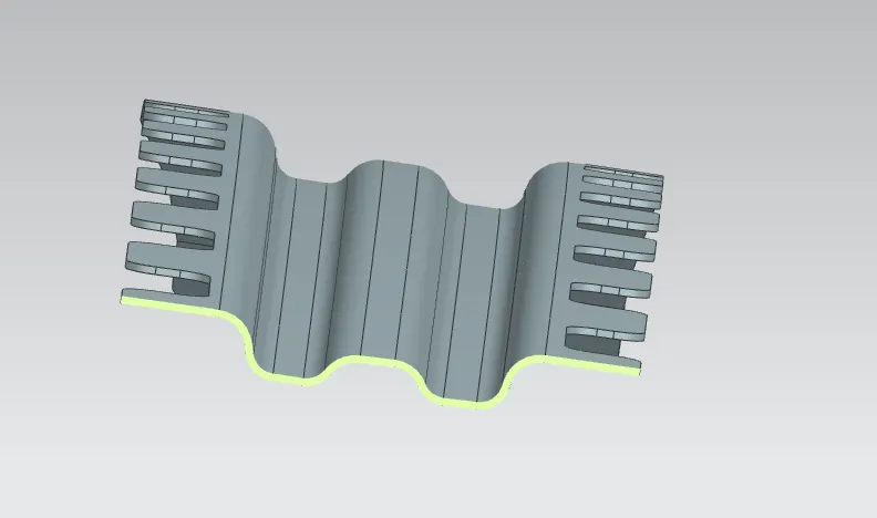
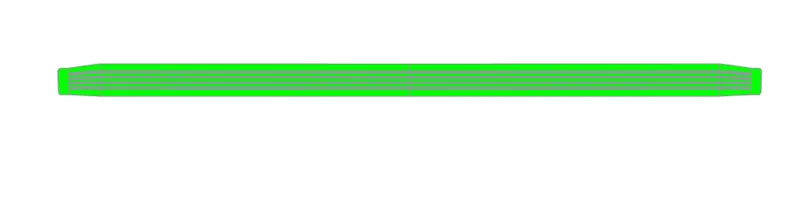
Bow Roof 2 is similar to that of bow roof 1. Bow roof 2 is also used to provide the strength of the roof.
Bow roof are give to improve the torsional stiffness and load bearing capacity of the roof structure.
Member of bow roof present is depending on the overall size of the roof.
Rear Roof Rail
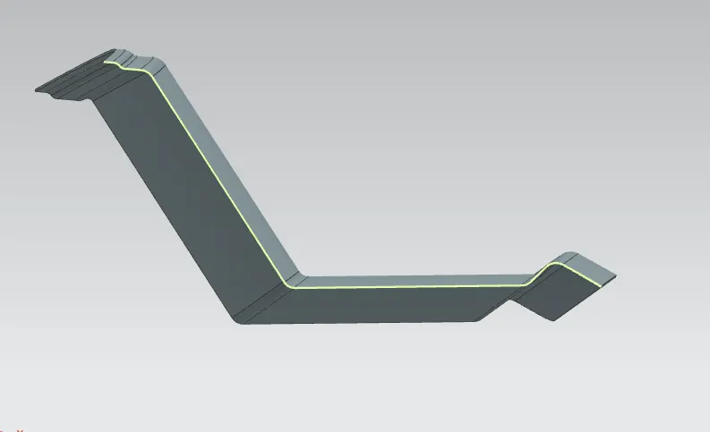
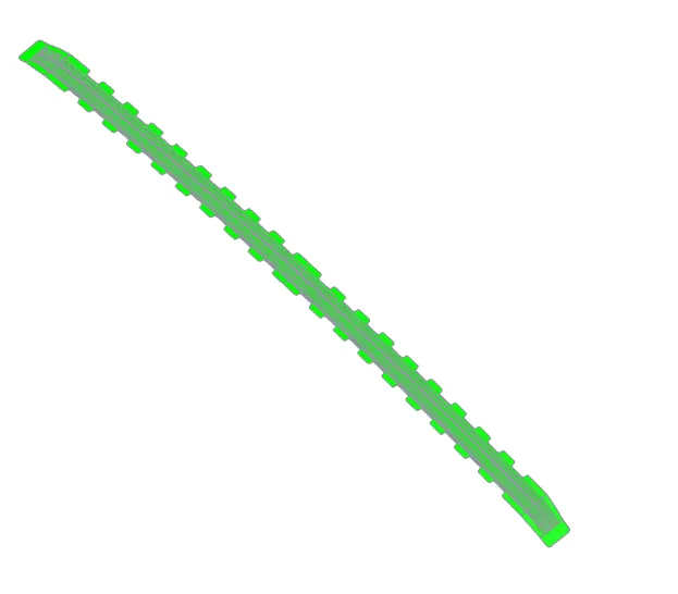
Rear roof rail is the one of the important components of roof assembly which is used for the back door mounting similar to front roof rail important design consideration include rear passenger head clearance rear visibility of the vehicle. It is also improving the strength of the roof.
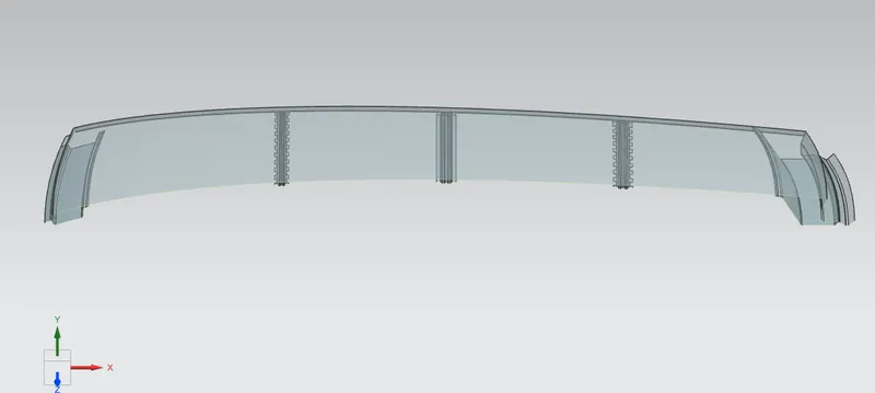
Finally Roof Assembly
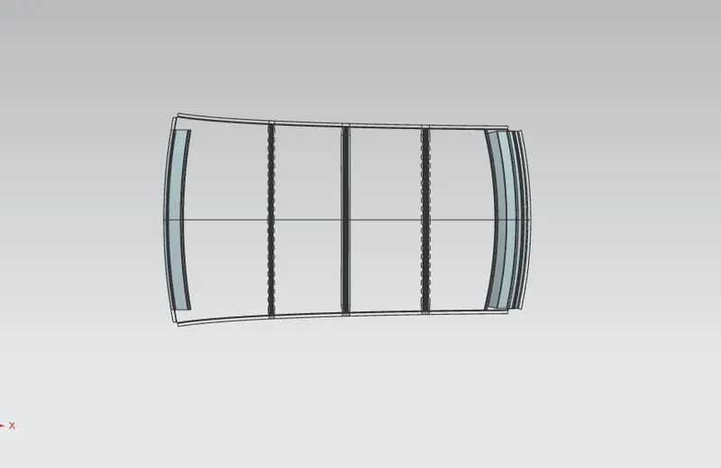
After assembly all the parts.
Assembly Cut Section View
Roof Test
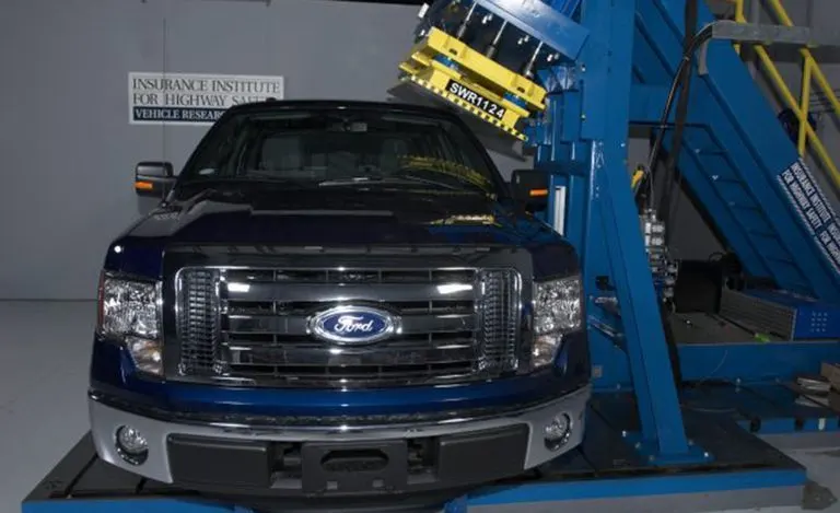
Roof Crush Test
In this test, a metal plate is pneumatically forced downward onto the roof of a car. The roof is crushed exactly five inches, and the force, which IIHS calls the strength-to-weight ratio, needed to do this is calculated. The more force needed to crush the roof five inches, the greater the likelihood that the car would perform well in a rollover.
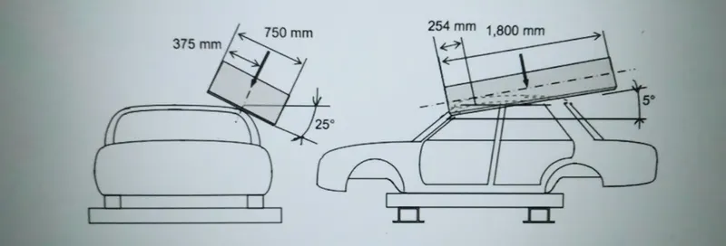
The load is applied in such a way that 5 deg. Is tilted from the front end to the rear end and the load will be in 1800 mm in length and 750mm in width. The load is applied at the position of 25 deg. From the flatness of the roof. The load is applied on the roof for almost 120 sec.
Heat Distortion on the roof
The heat distortion study plays an important role in sheet metal usage. Heat distortion temperature is a temperature limit above which the material cannot be used for structural application.
This study is used to predict the heat distortion temperature at where the material starts to soften when exposed toa fixed load at elevated temperature. In order to avoid bending/ damages on roof, based on heat distortion temperature, this study will predict the bow roof position on the roof to strengthen the roof.
W = [1.73 x 10^-3 x L] + [1.85 x 10^-8 x (R^2)/t] + [ 1.10 x 10^ (-3) x l] – 2.68
Were
L = Roof Length (mm)
R = Roof Curvature
R= 2(Rx*Ry)/(Rx+Ry)
Rx = X Curvature
Ry = Y Curvature
t = Roof Thickness(mm)
l = Bow Roof Span(mm)
Judgment Condition
OK< 2.7
| S.No. | BOW | Rx | Ry | R | I | L | t | W | OK/NG |
| 1 | FR&1st | 5701.04 | 2954.71 | 3892.19 | 488.2 | 2030.13 | 0.75 | 1.7427 | OK |
| 2 | 1st & CTR | 4855.16 | 6667.92 | 5618.92 | 387.8 | 2030.13 | 0.75 | 2.0374 | OK |
| 3 | CTR & 2nd | 3989.95 | 10517.7 | 5785.23 | 412.5 | 2030.13 | 0.75 | 2.1113 | OK |
| 4 | 2nd & RR | 3326.76 | 14283.4 | 5396.59 | 375.3 | 2030.13 | 0.75 | 1.9633 | OK |
Snow Load Criteria
This test is done to know how is the roof behaving when there is a snow over. Normally due to the snow weight the dent and damages will happen but the roof should be designed in such a way that when the snow is removal the roof should go it its original position.
Roof design must pass through these calculations to ensure that it has sufficient stiffness to withstand the load due to accumulation of snow over the roof.
Qr = [Iy x t^2]/ [α x s x [(Rx + Ry)/2] ^2 x 10^-8]
Where
α = My x Lx^2 x 10^-12
My = Y (Ly -Y)
t = Roof plate thickness
Ly = Distance between front and rear roof rail
Lx = Distance between the left and right end of the roof
Y = Distance from front roof rail center to bow roof in mm
S = L1/2 + L2/2
Iy = Geometrical moment of inertia
Rx = Lateral Direction curvature radius of the roof panel
Ry = Longitudinal Direction curvature radius of the roof panel
Judgment condition
Qr ≥ 3.1
250 ≤ s ≤ 380
| S.No. | BOW | Rx | Ry | Lx | Ly | L1 | L2 | y | t | α | s | Iy | Qr | Determination(Qr) |
| 1 | FR&1st | 4327.29 | 2922.55 | 1130.8 | 2030.13 | 554.2 | 431.2 | 554.2 | 0.75 | 1.0459 | 492.7 | 3552.3 | 29.5086 | Ok |
| 2 | 1st & CTR | 3793.69 | 6596.24 | 1083.1 | 2030.13 | 431.2 | 463.2 | 431.2 | 0.75 | 0.8088 | 447.2 | 20386 | 117.4741 | Ok |
| 3 | CTR & 2nd | 4270.22 | 11008.8 | 1058.8 | 2030.13 | 463.2 | 467.4 | 463.2 | 0.75 | 0.8136 | 465.3 | 9171 | 23.3468 | Ok |
Moment of inertia of BOW
Bow 1
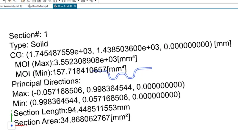
MOI max :- 3.5523 x 10^3 mm^4
MOI Min :- 157.7184 mm^4
Center Bow
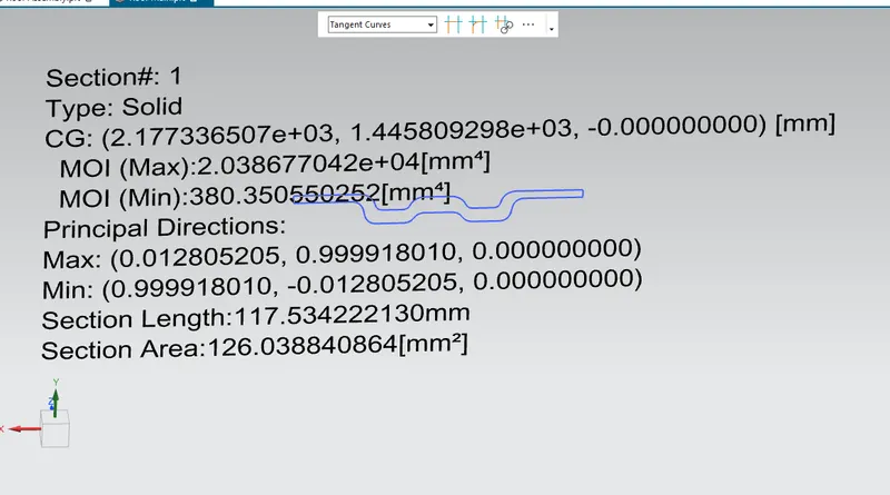
MOI max :- 2.0386 x 10^4 mm^4
MOI Min :- 380.3505 mm^4
Bow 2
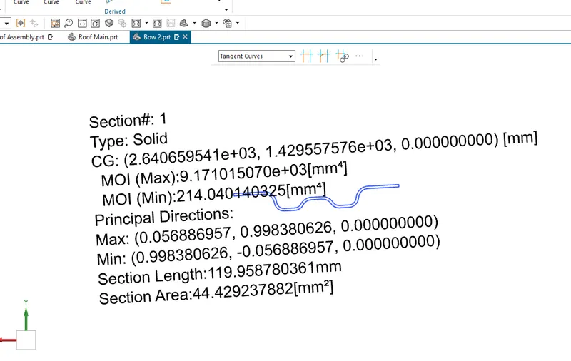
MOI max :- 2.6406 x 10^3 mm^4
MOI Min :- 214.0401 mm^4
Draft Analysis
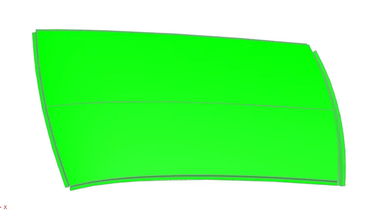
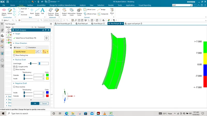
The Draft Analysis command enables you to detect if the part you drafted will be easily removed. This type of analysis is performed based on color ranges identifying zones on the analyzed element where the deviation from the draft direction at any point, corresponds to specified values. The draft of the part is the amount of taper of the edges to the striking mould of the part. The draft allows for easy removal of the part from the striker while an improper draft or negative draft causes the part to deform or get stuck on the mould.
In the draft analysis green color infer on the parts that all face along the tooling direction has positive draft angle. Green color shows the positive draft angle.
Roof Sheet
Front Roof Rail
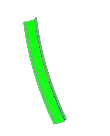
Bow 1
Center Roof Rail
Bow 2
Rear Roof Rail
Conclusion
Thus the roof of the car is designed as per the given skin data and master sketch. The roof is also analysed as per the heat distortion and snow load conditions and is found to be within limits. Draft analysis is also carried on all the components and there are no issues in this regards. finally roof is complete design.