Roof challenge
Introduction:
Automobile roof is the top portion of the car above the passenger compartment. Its main function is to protect the passengers from external elements to enter into passenger compartment and safety point of view related to roll over of car during accidents. Also consider the Headroom clearance, visibility Criteria , Windshield component.
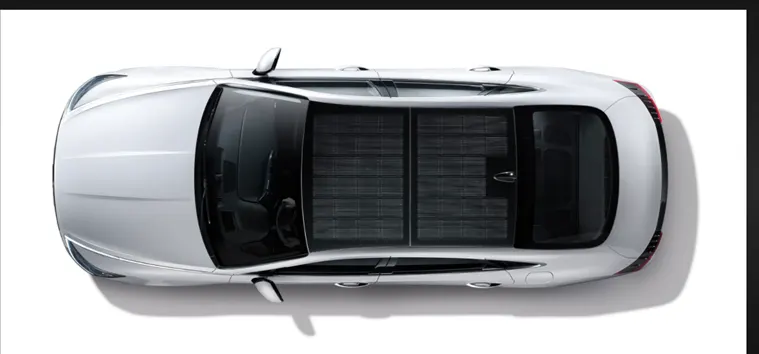
Sample Images
Designing of Roof:
Thus Roof Styling is provided for designing with the essential flanges and reinforcements. Provided with the five support surfaces to strengthen the roof base from bending or deformation. The five flanges or reinforcements are Front Roof Rail, Back Roof Rail, Center Roof reinforcement, Bow Roof 1 and Bow Roof 2.
Requirements :
- Start with the creation of a roof ditch area the tool opening angle is only 3 degrees.
- Do a curvature study on the roof and perform calculations to determine the position of the Bow-roof.
- Do a Section Inertia study for the Master sections you create for the Front roof rail, Rear roof rail, Bow Roof Rail, and Rear Roof Rail.
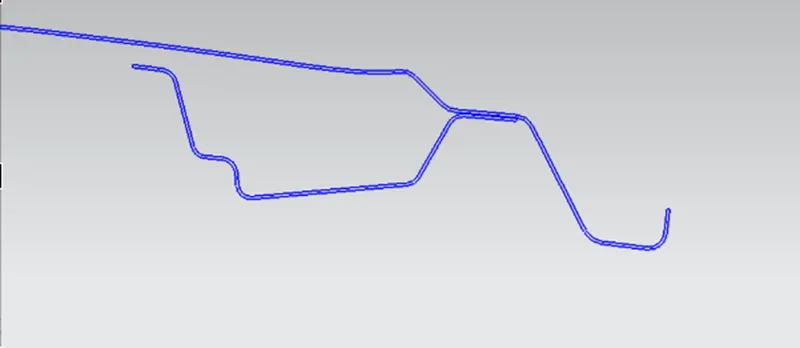
Master section of the rear roof rail
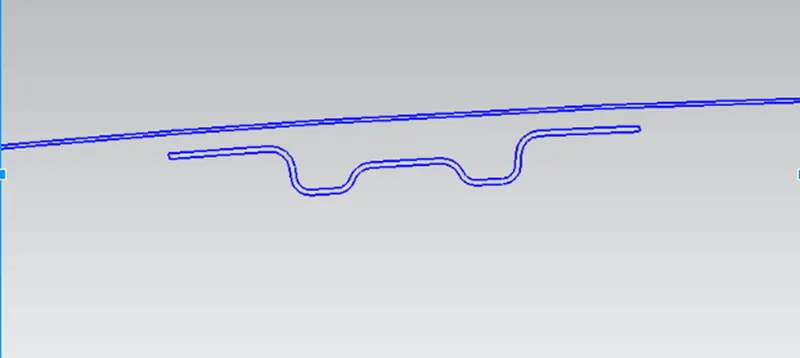
Master section of bow roof
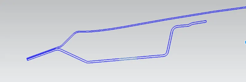
Master section of the front roof rail.
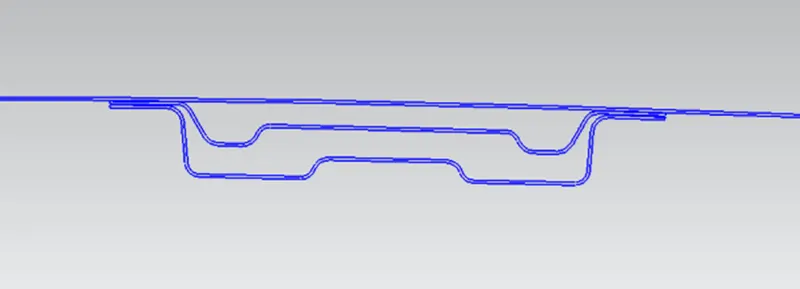
Master section of reinforcement center
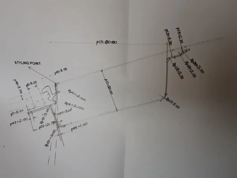
Front roof Rail master section reference image
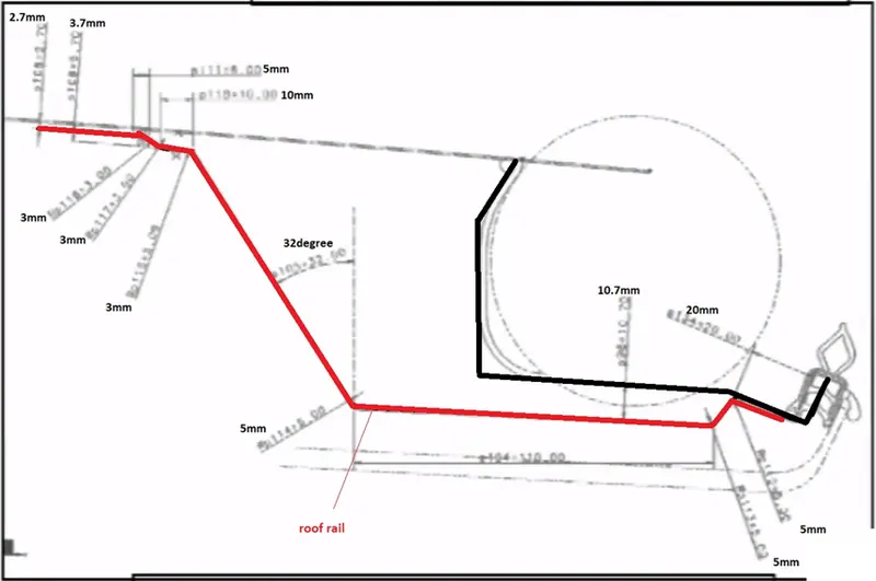
Rear roof rail master section reference image
Formulas :
Bow–roof prediction:
W = [1.73 x 10^(-3) x L] + [1.85 x 10^(-8) x (R^2)/t] + [ 1.10x10^(-3) x l] - 2.68
Judgement Condition : OK< 2.7> 3.1
Where
R = 2(Rx*Ry)/(Rx+Ry)
L = Roof Length in X-Direction[mm](Roof dimension in 0-Y)
R = Roof curvature
Rx = X curvature
Ry = Y curvature
t = Roof plate thickness [mm]
l = Bow Roof Span [mm]
Snow load Prediction:
Qr = [Iy x t2] / [α x s x [(Rx + Ry)/2]2 x 10-8]
Where
α = My x Lx2 x 10-12 , My = Y(Ly -Y)
s = L1/2 + L2/2
Judgement condition = Qr ≥ 3.1 ; 250 ≤ s ≤ 380
t = Roof plate thickness [mm]
Ly = Distance between the front and rear roof Rails on the Vehicle along with 0Y[mm]
Length of Roof panel with the center point between Roof rail Front /Rear as the front and rear reference point.
Lx = Distance between the Left and Right end of the roof on the Roof BOW [mm]
Width of the roof panel exposed on the surface.
Y = Distance front Front Roof Rail to Roof BOW[mm]
s = Distance for which Roof BOW bears divided load [mm]
Iy = Geometrical moment of inertia of Roof BOW (Y cross-section )[mm4]
Rx = Lateral direction curvature radius of roof panel Y cross-section on Roof BOW [mm]
Roof panel curvature Radius of the Length Lx in Front view
Ry = Longitudinal Direction curvature radius of the Roof panel X cross-section on Roof BOW [mm]
Roof panel X curvature radius of length s in Side view
Roof Design Flanges and reinforcements:
Design is made using the top down approach from the provided styling surface. projecting the outer surface of the styling design and provide suitable draft angle as mentioned in the master design
Front Roof Rail:
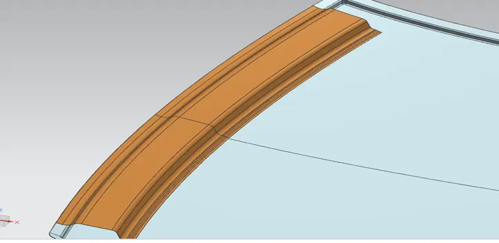
FRR is created based on the master section standards. Styling surface is taken as reference and FRR has been made as per the dimensions and angle provided with the consideration of draft angle for manufacturing feasibility.
Rear Roof Rail:
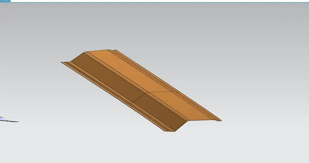
Styling surface is taken as reference and RRR has been made as per the dimensions and angle provided with the consideration of draft angle for manufacturing feasibility.
Center Reinforcement:
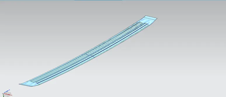
CR is created based on the standards with 50% of arc length from Styling surface in linear direction with symmetric style of design. Styling surface is taken as reference and FRR has been made as per the dimensions and angle provided with the consideration of draft angle for manufacturing feasibility.
Bow Roof 1:
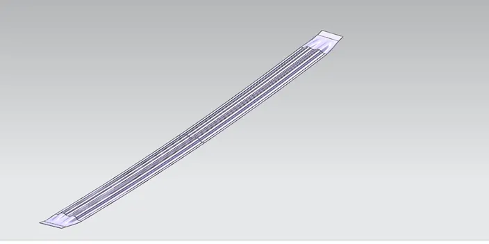
BR1 is created based on the standards with 33% of arc length from Styling surface in linear directionwith symmetric style of design. Styling surface is taken as reference and FRR has been made as per the dimensions and angle provided with the consideration of draft angle for manufacturing feasibility.
Bow Roof 2:
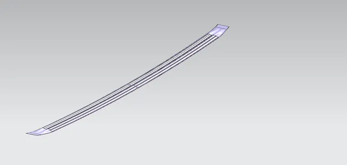
BR1 is created based on the standards with 75% of arc length from Styling surface in linear direction with symmetric style of design. Styling surface is taken as reference and FRR has been made as per the dimensions and angle provided with the consideration of draft angle for manufacturing feasibility.
Assembly:
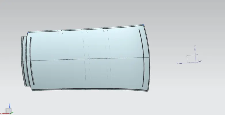
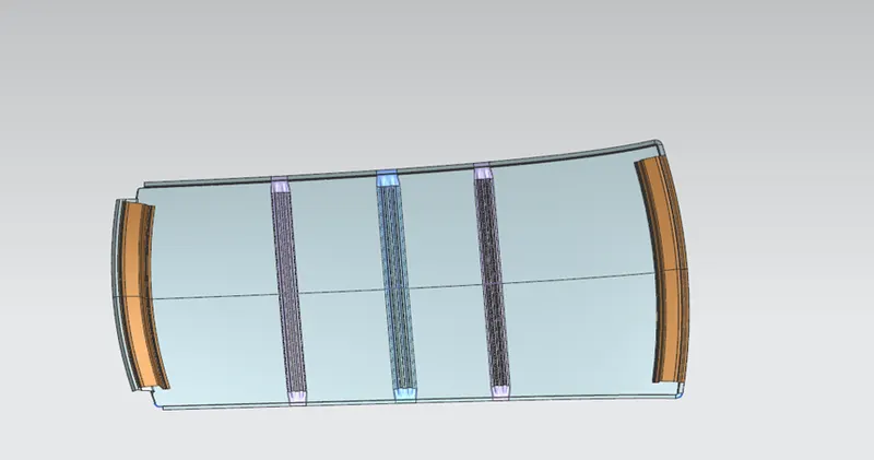
Thus Roof Stylling surface is fixed and other five components are assembled in their respective positions with the consideration of joining process . Thus the end portion of the styling surface and bow roofs are attached with spot welding and center portion is supported by using the mastics.
Heat Distortion Criteria:
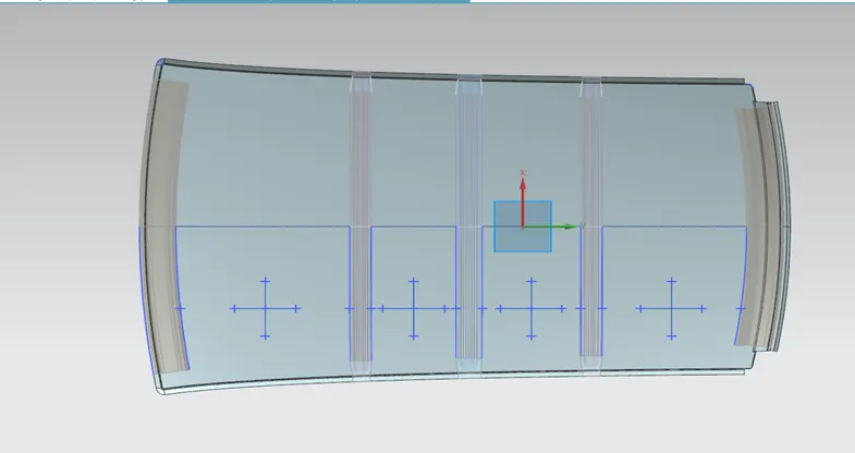
The defelection of the surface when exposed to the temperature above its mentioned limit.
Procedure:
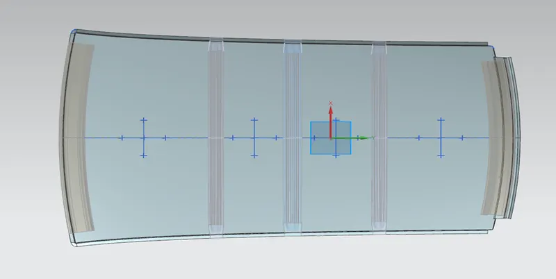
Create a center line in oy direction and offset it to -3y distance from there offset 100mm on both side and make centerline between the FRR to BR1 and offset by 100mm on both side so we get three points on horizontal and vertical direction.
Formula:
W = [1.73 x 10^(-3) x L] + [1.85 x 10^(-8) x (R^2)/t] + [ 1.10x10^(-3) x l] - 2.68
R = 2(Rx*Ry)/(Rx+Ry)
Judgement Condition : OK< 2.7> 3.1
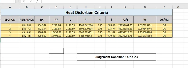
Thus Detailed calculations is carried out in the excel sheet attached with the report.
Snow Load Predection:
Downward force on the roof surface of the car by the weight of the accumulated snow or ice.
Procedure:
Create a center line in oy direction from there offset 100mm on both side and make centerline between the FRR to BR1 and offset by 100mm on both side so we get three points on horizontal and vertical direction.
Formula:
Qr = [Iy x t2] / [α x s x [(Rx + Ry)/2]2 x 10-8]
α = My x Lx2 x 10-12 , My = Y(Ly -Y)
s = L1/2 + L2/2
Judgement condition = Qr ≥ 3.1 ; 250 ≤ s ≤ 380
Moment of Inertia :
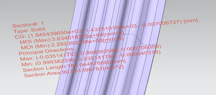
Iy for Section Bow Roof 1
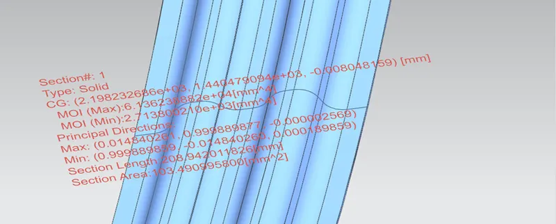
Iy for Section Center Roof Reinforcement
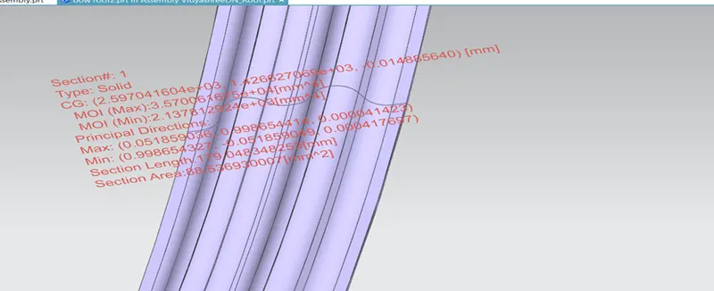
Iy for Section Bow Roof 2
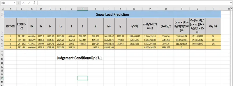
Thus the design is not satisfied for the snow load conditions. so we need to strengthen the styling surface by providing the emposs. so the strength of the component is increased and it can able to satisy the snow load conditions.
Draft Analysis:
Enables to detect whether the part you drafted will be easily removed after being manufactured. This analysis is performed and we obtain the color graph with identifying zones on the analyzed element where the deviation from the draft direction at any point, corresponds to specified values.Draft analysis is carried out for each part.
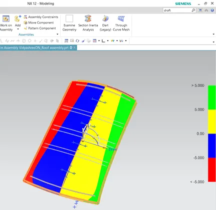
Roof Styling surface
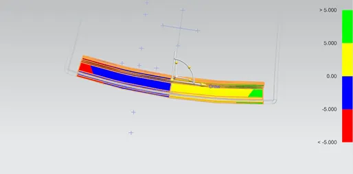
Front Roof
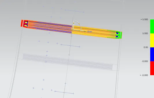
Center roof reinforcement
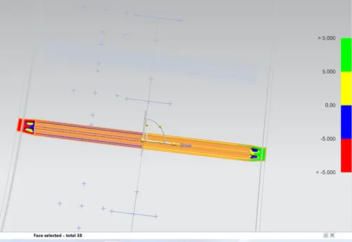
Bow Roof1
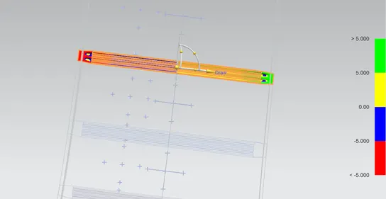
Bow Roof 2
Conclusion :
Thus the roof design is made as per standards and determine whether it will satisfy the heat distortion criteria and snow load conditions and also how to provide the strength to the structure so that it can withstand against deformation during roll over.