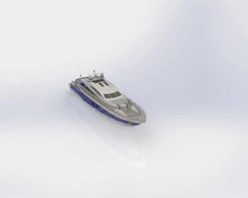
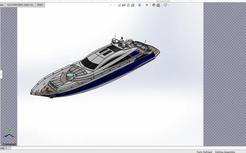
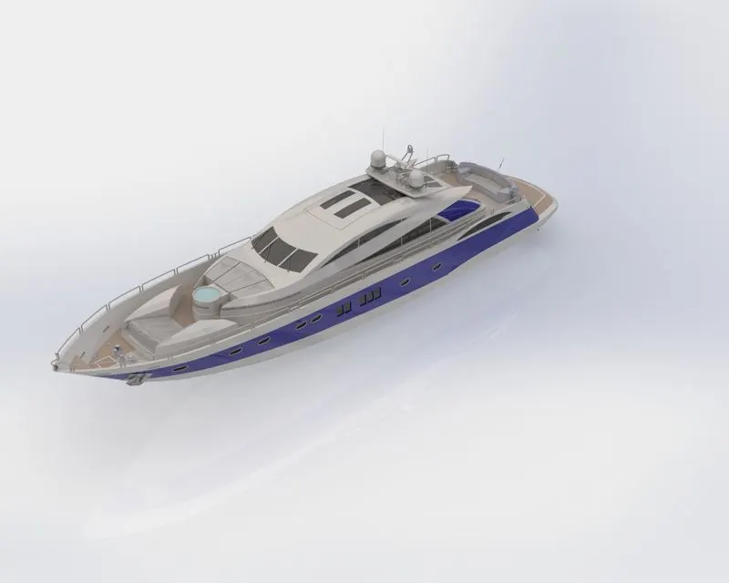
Radar Mast & Final Assembly of Yacht
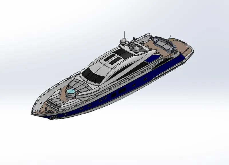
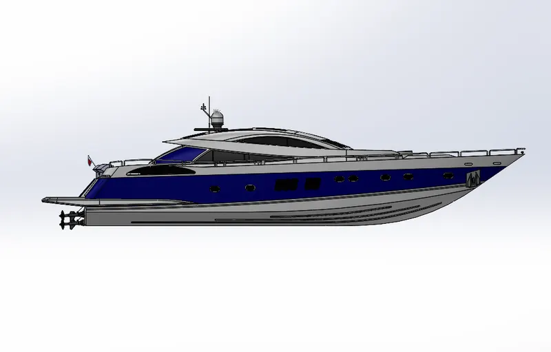
MODELLING OF SUNSEEKER PREDATOR YACHT ON SOLIDWORKS
OBJECTIVE
- Creating individual parts of the yacht.
- Assembling all the parts of the yacht.
- Application of decals, lights and camera.
- Rendering the yacht using photoview 360.
INTRODUCTION
- Designing of different parts of yacht and assembling them to get a complete model of the yacht using Solidworks is explained in this project.
- It also tells about the rendering of the model using Solidworks Visualize to make the yacht more natural and realistic.
The features and properties used in the entire model to design different parts
Surface extrude
- The surface extrude is the most basic of all SOLIDWORKS features and extrudes a sketch along a straight-line path to add material.
- As a sketched feature, it requires a sketch before use. Once the sketch has been created, exit the sketch and select the Features tab of the Command Manager.
- Then, click the surface extrude command. If a yellow dialog box appears in the Property Manager asking you to create a new sketch, click on the sketch in the graphics area to use it for the feature. The Property Manager for the surface extrude allows you to control starting location, extrude depth for the feature, among several other parameters.
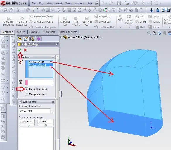
Knit surface
- This tool helps in joining the surfaces.
Extrude Boss:
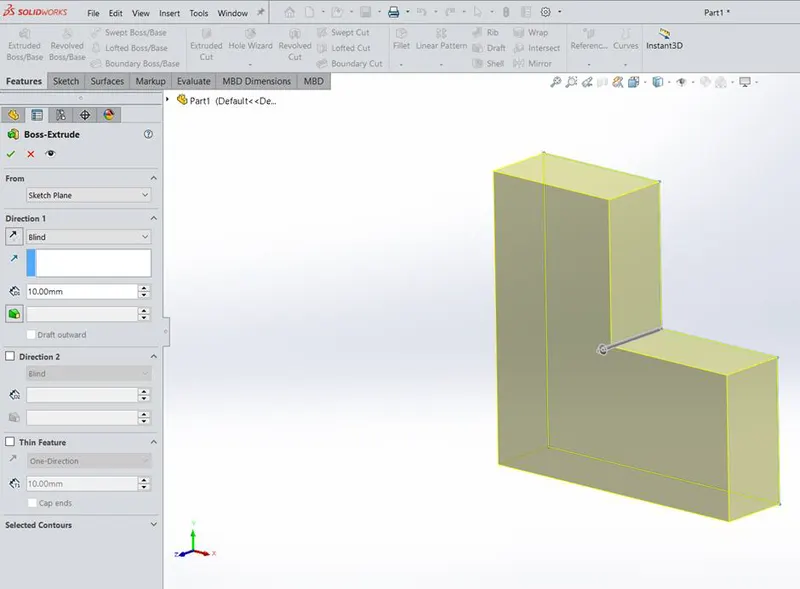
- The Extruded Boss is the most basic of all SOLIDWORKS features and extrudes a sketch along a straight-line path to add material.
- As a sketched feature, it requires a sketch before use. Once the sketch has been created, exit the sketch and select the Features tab of the Command Manager.
- Then, click the Extruded Boss/Base command. If a yellow dialog box appears in the Property Manager asking you to create a new sketch, click on the sketch in the graphics area to use it for the feature. The Property Manager for the Extruded Boss allows you to control starting location, extrude depth and draft for the feature, among several other parameters.
Fillet
- Fillets are classified as applied features, and as such do not require a sketch to be used.
- Fillets serve to round off edges and/or corners by adding or removing material, depending on whether the edge is internal or external.
- It should be noted that fillets of different sizes must be created as separate features. Typically, it is best practice to create the largest fillets first and follow with smaller fillet
Revolved Boss Feature
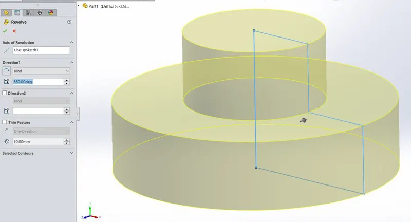
Adds material by revolving a sketch around an axis. Remember, once geometry has been created in your model, any flat face can be used as a sketching surface. It is very important to draw an axis in the sketch which needs to be revolved.
Extrude Cut
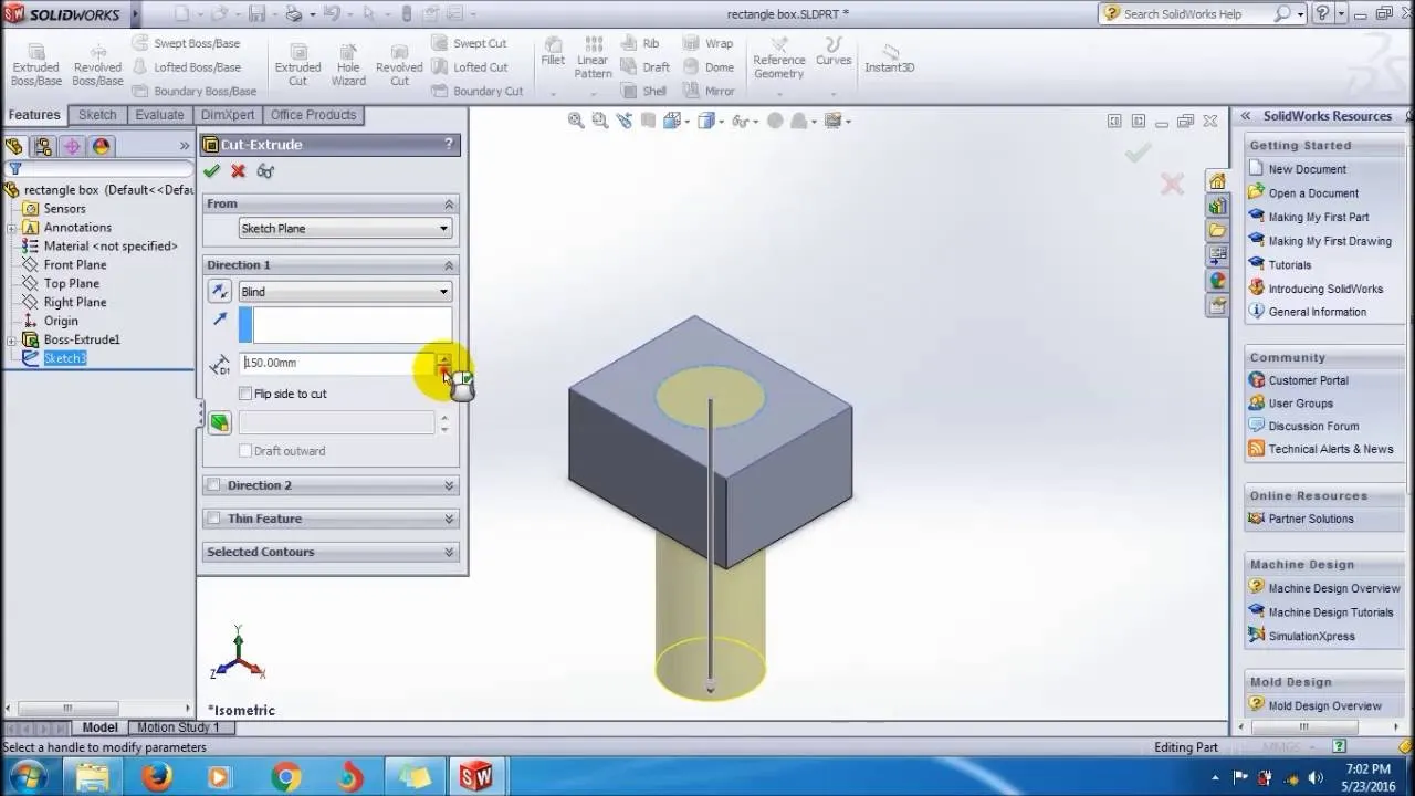
Similar to the extrude boss feature this feature needs a sketch on the solid body which needs to be cut and the desired shape is then cut off.
Shell
SolidWorks shell tool is mainly used for shelling process, in which the material removed from the inner body of model by keeping small thickness and results a hollow model. Using this tool, you can make either completely closed hollowed model or one face opened type.
Sweep Boss / Sweep Cut
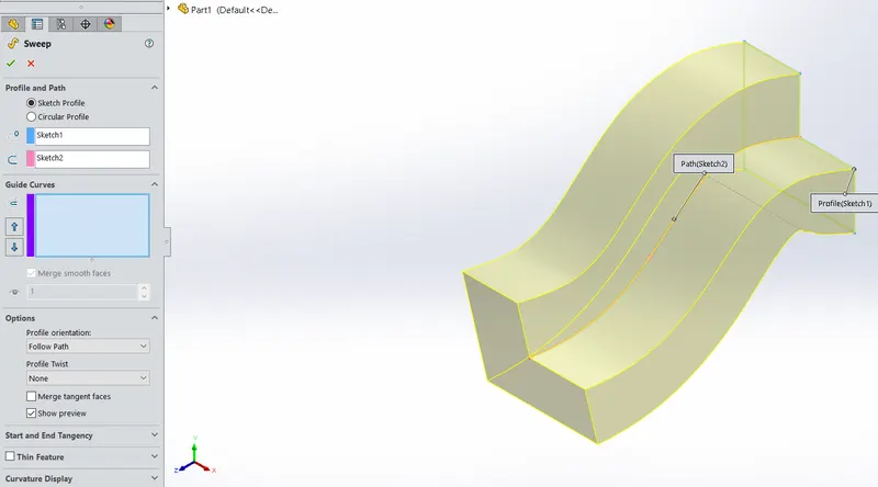
Sweep creates a base, boss, cut, or surface by moving a profile (section) along a path, according to these rules: The profile must be closed for a base or boss sweep feature; the profile may be open or closed for a surface sweep feature.
Loft Boss/ Loft Cut
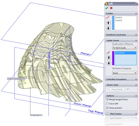
The loft feature is an important tool for (surface) modelling in SolidWorks. The loft feature creates a shape by making transitions between multiple profiles and guide curves. This tool is very valuable for modelling complex surfaces. You can do some cool stuff when you use this feature properly.
Mirror
Creates a copy of a feature, (or multiple features), mirrored about a face or a plane. You can select the feature, or you can select the faces that comprise the feature. Bodies to Mirror: Select a body in a single model or multibody part to create a mirror entity. Multibody parts: Apply features to one or more multibody parts by selecting Geometry Pattern and using Feature Scope to choose which bodies should include the feature.
Reference Geometry
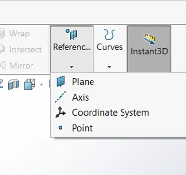
Reference geometry defines the shape or form of a surface or a solid. Reference geometry includes items such as planes, axes, coordinate systems, and points.
Projected Curve
You can project a sketched curve onto a model face to create a 3D curve. You can also create a 3D curve that represents the intersection of two extruded surfaces generated by creating sketches on two intersecting planes. You can create multiple closed or open-contour projected curves from a single sketch. You can also use 3D sketches as input for the Projected Curve tool. Note: the Projected Curve tool does not support projections of intersecting curves.

Mate
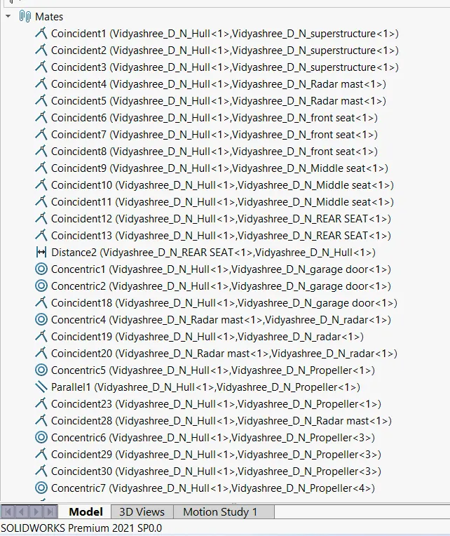
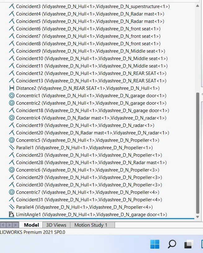
Mates create geometric relationships between assembly components. As you add mates, you define the allowable directions of linear or rotational motion of the components. You can move a component within its degrees of freedom, visualizing the assembly's behaviour.
Some examples include:
- A coincident mate forces two planar faces to become coplanar. The faces can move along one another but cannot be pulled apart.
- A concentric mate forces two cylindrical faces to become concentric. The faces can move along the common axis but cannot be moved away from this axis.
DESIGN APPROACH
Description
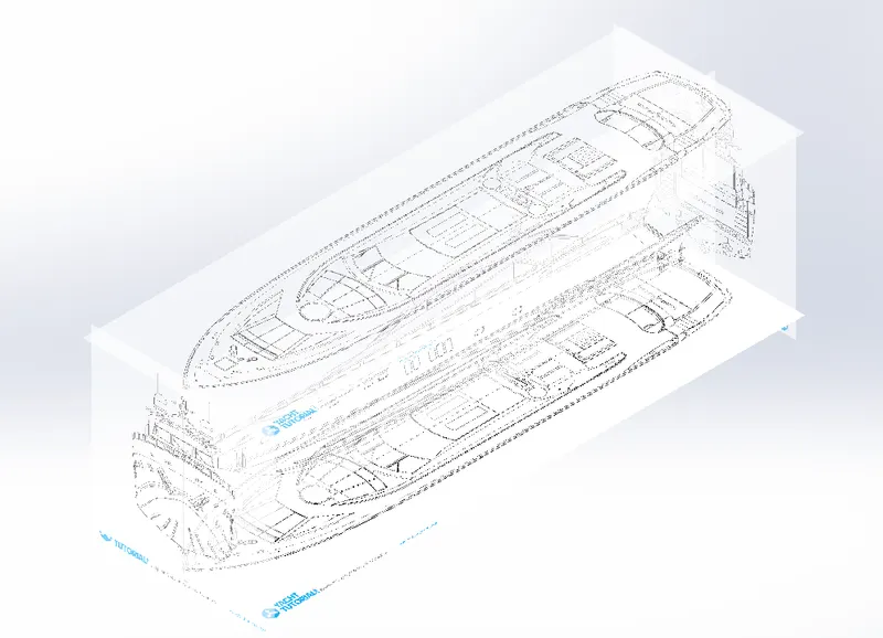
BLUEPRINT SETUP
- Blueprint is set as reference for the rest of the modleling process.
HULL
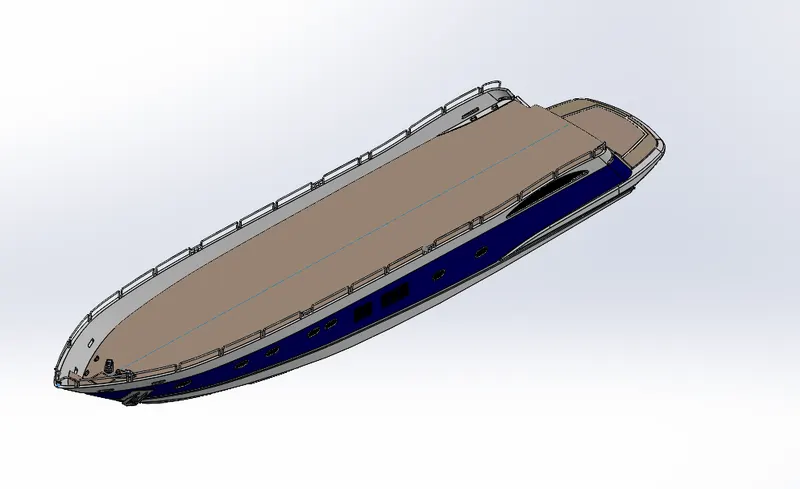
- The main part of the yacht is the hull.
- It is essentially the surface modeling.
- The outer surface is created by surface extrude and projected curves.
- Lofted surface, fill surface, boundary surfaces are used in the surface modelling
- The surfaces are later trimmed, knitted and merged to create a solid body.
- The model is mirrored on the other side.
- Later appearances are set.
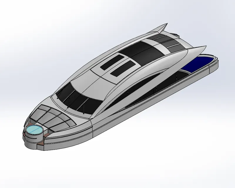
SUPERSTRUCTURE
- The second largest part of yacht is the superstructure
- It is essentially the surface modeling.
- The outer surface is created by surface extrude and projected curves.
- The outer surface is created by surface extrude and projected curves.
- Lofted surface, fill surface, boundary surfaces are used in the surface modelling
- The surfaces are later trimmed, knitted and merged to create a solid body.
- The model is mirrored on the other side.
- Later appearances are set
SEATINGS
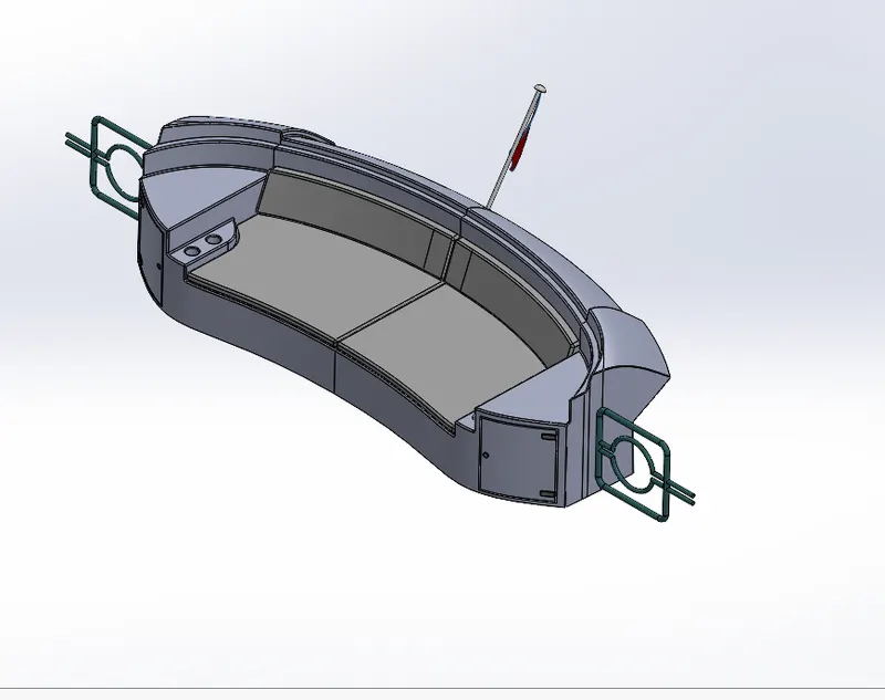
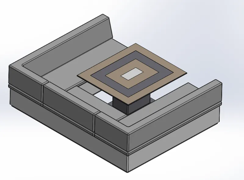
- There are three seatings present in this yacht.
- Front seat, rear seat and middle seat.
RADAR
- Radar is used in navigation for safety purpose
- It is modelled using extrude boss, fillets and split line for creating text on the radar
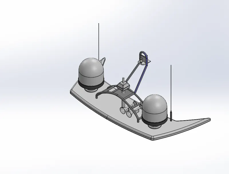
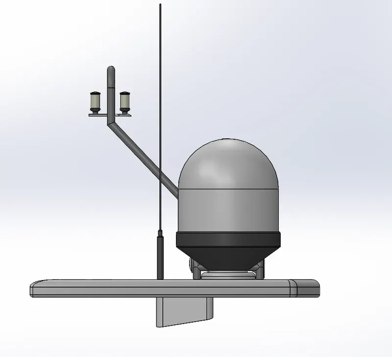
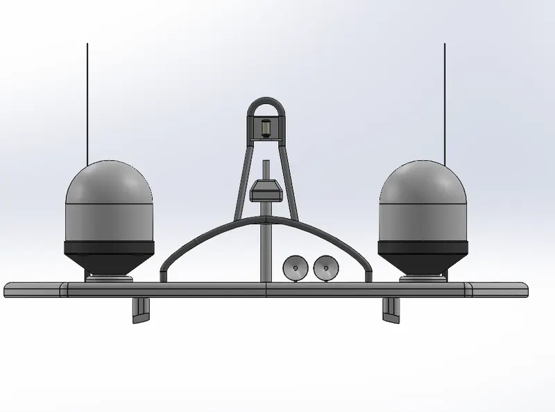
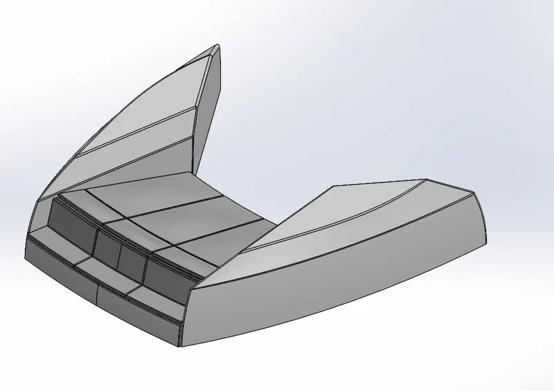
RADAR MAST
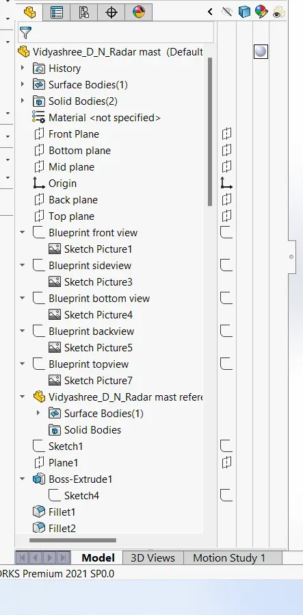
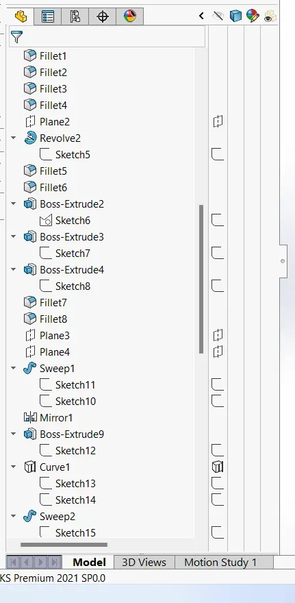
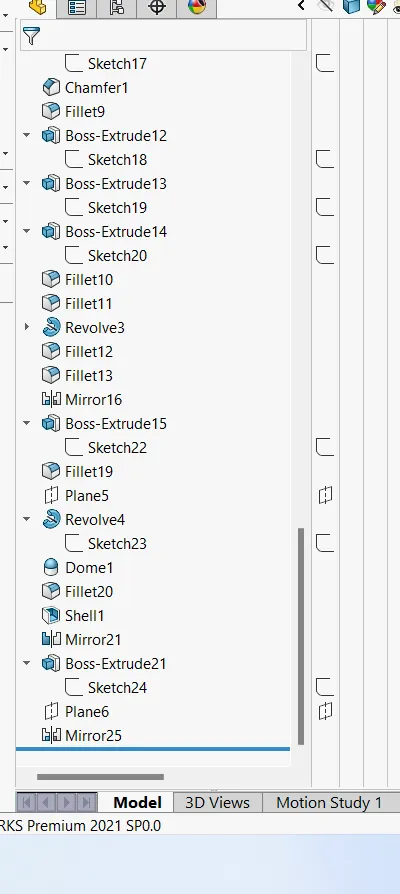
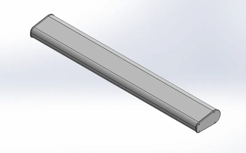
- The radar mast consists of 2 huge buls with antennas
- The horns are modelled using shell feature
- The part is easily modelled using extrude boss and revolve command.
PROPELLER
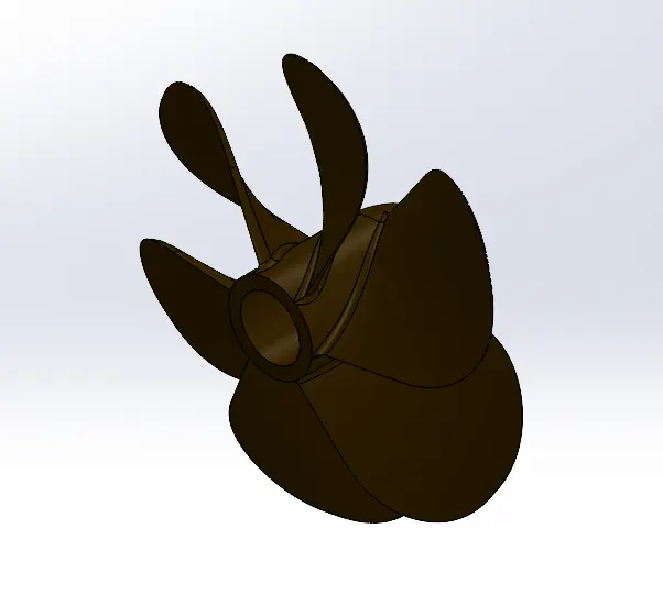
A propeller is a device with a rotating hub and radiating blades that are set at a pitch to form a helical spiral, that, when rotated, exerts linear thrust upon a working fluid, such as water or air.- It was created with a hub at the centre and blades by using fillets, dome surface extrude and etc feature.
GARAGE DOOR
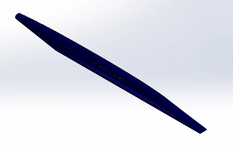
- This door is placed for the closure of the space provided to keep the vehicles.
- It is created with the help of extrude cut and boss extrude features.
Assembly
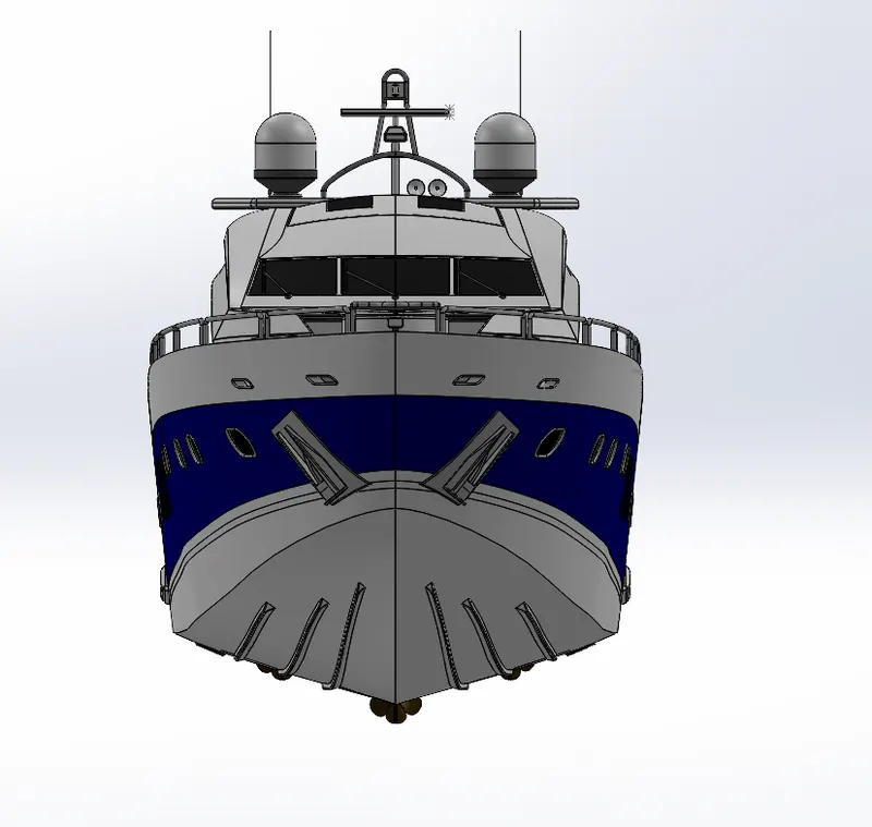
- After making all the parts the most important part of assembling the entire yacht to a single file begins.
- Relations between the planes and the surfaces has to be given.
RENDERING OF THE YACHT
In rendering, the yacht was made to set up in such a way to look natural and unique. Decals were added to the body parts. Views and light directions were changed. Using solidworks visualize, the appearances, background scenes and camera views were changed. Then final rendering was done to make the yacht, a cool and realistic one.
Conclusion
The parts of the yacht are modelled, assembled and rendered.