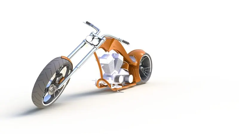
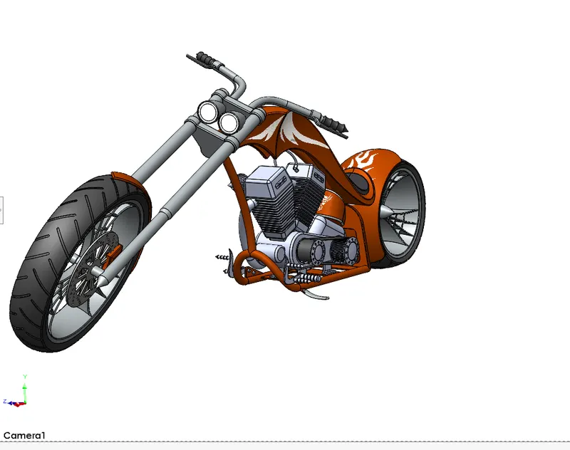
Photo Realistic Rendering
MODELLING OF AMERICAN CHOPPER ON SOLIDWORKS
OBJECTIVE
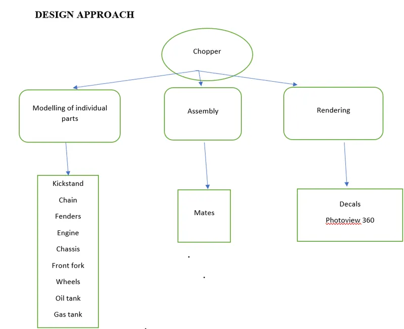
- Creating individual parts of the chopper.
- Assembling all the parts of the chopper.
- Application of decals, lights and camera.
- Rendering the chopper using photoview 360.
INTRODUCTION
- Designing of different parts of chopper and assembling them to get a complete model of the chopper using Solidworks is explained in this project.
- It also tells about the rendering of the model using Solidworks Visualize to make the chopper more natural and realistic.
The features and properties used in the entire model to design different parts
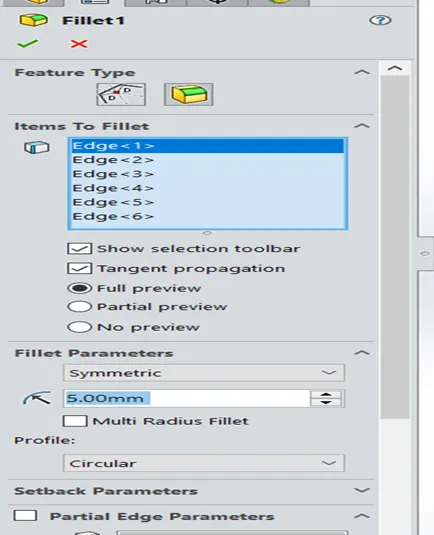
Fillet
- Fillets are classified as applied features, and as such do not require a sketch to be used.
- Fillets serve to round off edges and/or corners by adding or removing material, depending on whether the edge is internal or external.
- It should be noted that fillets of different sizes must be created as separate features. Typically, it is best practice to create the largest fillets first and follow with smaller fillet
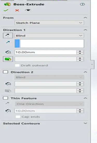
Extrude Boss
- The Extruded Boss is the most basic of all SOLIDWORKS features and extrudes a sketch along a straight-line path to add material.
- As a sketched feature, it requires a sketch before use. Once the sketch has been created, exit the sketch and select the Features tab of the Command Manager.
- Then, click the Extruded Boss/Base command. If a yellow dialog box appears in the Property Manager asking you to create a new sketch, click on the sketch in the graphics area to use it for the feature. The Property Manager for the Extruded Boss allows you to control starting location, extrude depth and draft for the feature, among several other parameters.
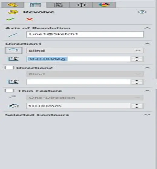
Revolved Boss Feature
Adds material by revolving a sketch around an axis. Remember, once geometry has been created in your model, any flat face can be used as a sketching surface. It is very important to draw an axis in the sketch which needs to be revolved.
Extrude Cut
Similar to the extrude boss feature this feature needs a sketch on the solid body which needs to be cut and the desired shape is then cut off.
Shell
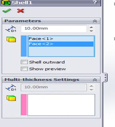
SolidWorks shell tool is mainly used for shelling process, in which the material removed from the inner body of model by keeping small thickness and results a hollow model. Using this tool, you can make either completely closed hollowed model or one face opened type.
Sweep Boss / Sweep Cut
Sweep creates a base, boss, cut, or surface by moving a profile (section) along a path, according to these rules: The profile must be closed for a base or boss sweep feature; the profile may be open or closed for a surface sweep feature.
Loft Boss/ Loft Cut
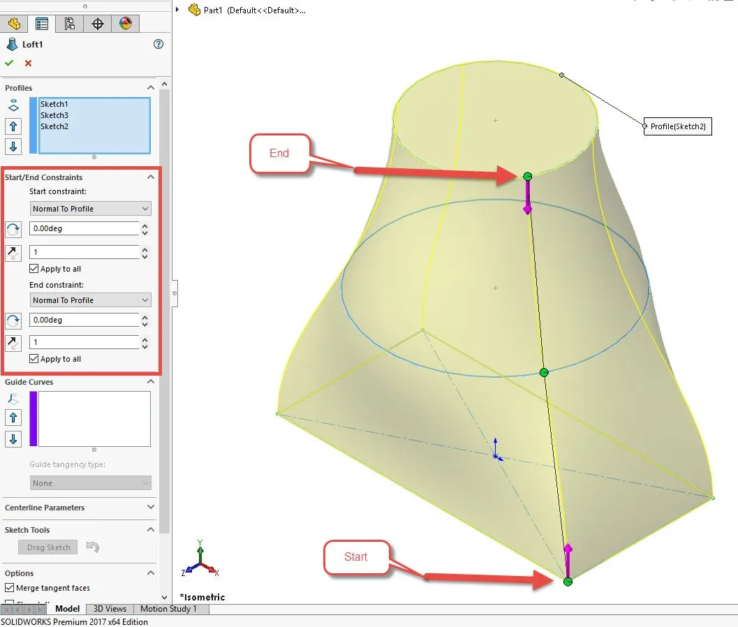
The loft feature is an important tool for (surface) modelling in SolidWorks. The loft feature creates a shape by making transitions between multiple profiles and guide curves. This tool is very valuable for modelling complex surfaces. You can do some cool stuff when you use this feature properly.
Mirror
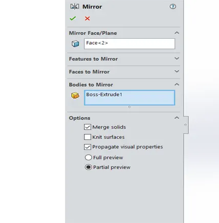
Creates a copy of a feature, (or multiple features), mirrored about a face or a plane. You can select the feature, or you can select the faces that comprise the feature. Bodies to Mirror: Select a body in a single model or multibody part to create a mirror entity. Multibody parts: Apply features to one or more multibody parts by selecting Geometry Pattern and using Feature Scope to choose which bodies should include the feature.
Reference Geometry
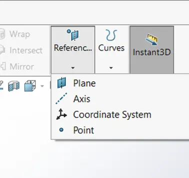
Reference geometry defines the shape or form of a surface or a solid. Reference geometry includes items such as planes, axes, coordinate systems, and points.
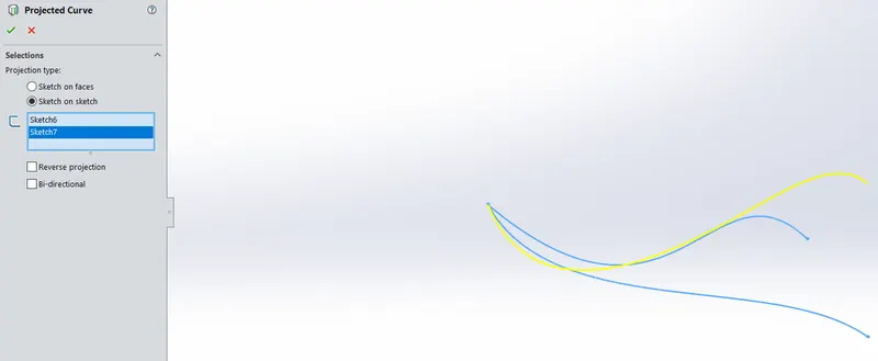
Projected Curve
You can project a sketched curve onto a model face to create a 3D curve. You can also create a 3D curve that represents the intersection of two extruded surfaces generated by creating sketches on two intersecting planes. You can create multiple closed or open-contour projected curves from a single sketch. You can also use 3D sketches as input for the Projected Curve tool. Note: the Projected Curve tool does not support projections of intersecting curves.
Mate
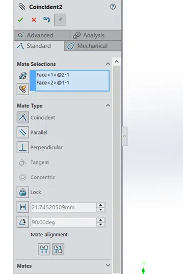
Mates create geometric relationships between assembly components. As you add mates, you define the allowable directions of linear or rotational motion of the components. You can move a component within its degrees of freedom, visualizing the assembly's behaviour.
Some examples include:
- A coincident mate forces two planar faces to become coplanar. The faces can move along one another but cannot be pulled apart.
- A concentric mate forces two cylindrical faces to become concentric. The faces can move along the common axis but cannot be moved away from this axis.
DESIGN APPROACH
Description
Transmission Belt
The solid body in transmission belt is a single extruded surface whose outer edge has been filleted and the appearance used is a matte rubber.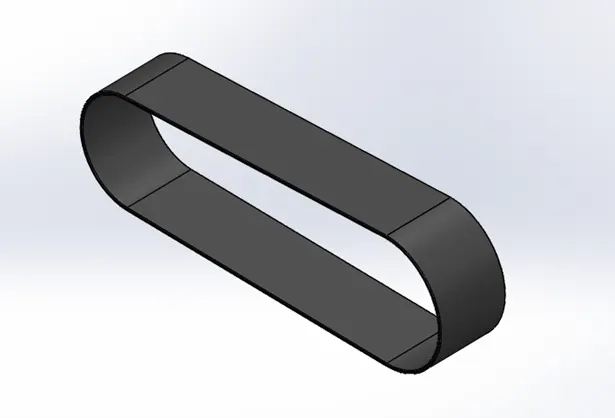
Kickstand
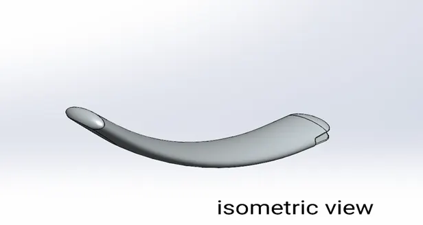
- A kickstand is usually a piece of metal that flips down from the frame and makes contact with the ground.
- The body of kickstand was created by using loft tool and dome was applied at the ends.
Chain
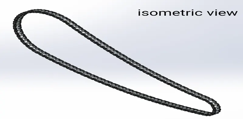
- Chain is used to transmit mechanical power from engine to rear wheel. Roller chain is the commonly used type. Though the chain is a complicated model, it was easily modelled by using mirror, curves and curve driven pattern.
- The links were modelled as blocks and later imported. The curve driven pattern was done multiple times to get the accurate result.
Fenders
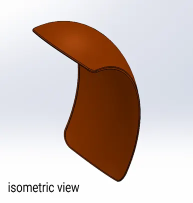
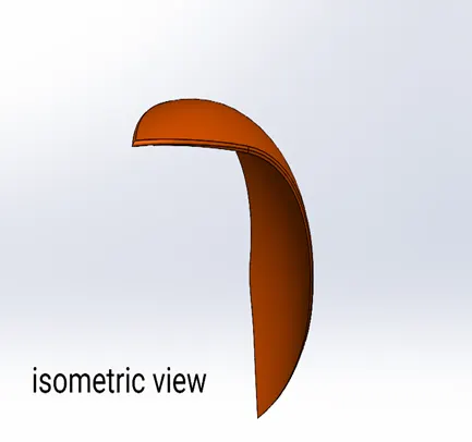
- A Fender is the part of a car, truck or motorcycle that surrounds the wheel well. The primary function of a Fender is to prevent dirt and debris from being thrown into the air by the tire.
- It was very easy to model these fenders. Both fenders are modelled by using features like revolve, split and other features with different dimensions
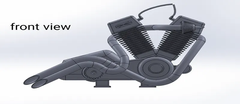
Engine
- Engine is the heart of bike. It provides the power necessary to drive the vehicle.
- A picture is imported for reference before modelling. First, bottom part of the engine, consisting of crank shaft, motor and transmission pulleys, was modelled.
- Then upper part of the engine with cooling fins are drawn. Then rear sprocket and air filter were modelled. Finally the exhaust system and spark plug were modelled using splines, projected curves and sweep features.
CHASSIS
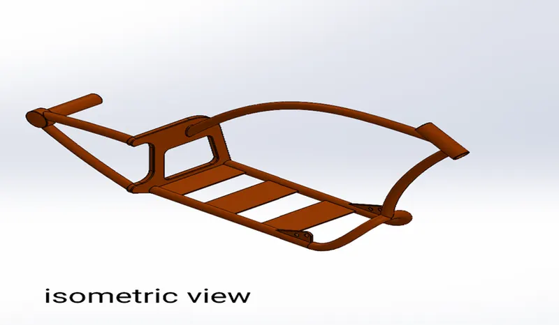
- Chassis is the main body of the chopper. It is the skeletal frame of the bike and holds other components like front fork, pedals, kickstand, oil tank, gas tank and engine.
- It provides strength and support to the bike. Its modelling was started by using a picture as a reference for sketching.
- It involved features like splines, projected curves and split. It took more time to model.
Front fork
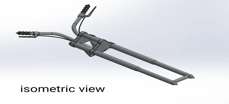
- A front fork connects a motorcycle's front wheel and axle to its frame, typically via triple clamps. Most forks incorporate the front suspension and front brake, and allow the front wheel to rotate about the steering axis so that the bike may be steered.
- This was modelled by using features like extrude and mirror. Projected curves were used to model the handles and cables. A special appearance was given to the headlights that shows them glowing.
Front and Rear Wheel
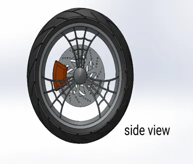
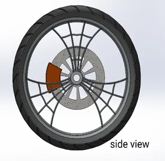
- The designing of both the wheels are similar the differences is in the size of the wheels.
- To begin a revolved part is created on the right plane which is the rim now the spokes are sketched on the right plane and extruded which is merged with the hub now to attain the spider web design on the spokes a sketch is made on the face of the spoke using the spline tool, converting entities and mirroring the part with proper references and construction geometries the sketch is then cut extruded and then a circular pattern is made along the edge of the rim to make three forks
- The calipers are sketched now on the face of the disk and extruded both sides which is then chamfered to attain the desired look and the edges are filleted, now the sprocket is designed on the same plane and with an extruded cylindrical hub which is attained by revolving now the pattern is sketch on the face of the sprocket and cut extrude is applied which is then patterned in the entire sprocket.
- Now the final sketch is made and revolved around to be the tire of the wheels and the sketch of the grips in the tires are drawn on the face of it using three point rectangles and then the entire geometry is cut extruded and a fillet is applied to all the sharp edges finally the layout is again patterned in a circular arrangement to make a realistic look and appearances are applied on the different solid bodies.
- The entire wheel consists of five solid parts Chrome finished Rims, Sienna metal painted Caliper, Chrome finished sprocket and matte rubber tires.
Gas tank
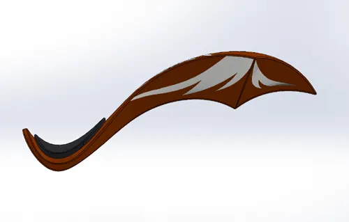
- The gas tank covers the oil tank and engine and also acts as a shield that prevents the heat from engine. The seat and opening for fuel tank are located on the top of gas tank.
- This also involved using a reference picture for sketching. One half of the tank was created and the mirrored. Then seat was modelled on the top of it and fillets were applied. Finally the tank was shelled to make it hollow.
Oil Tank
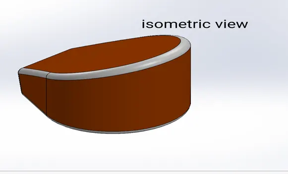
- The base of the oil tank is sketched on the Top Plane and extruded boss above now to attain the structure of the oil tank one more sketch is made on the mid plane extruded and combined together and at last a shell function is used to make the part hollow and the edges are made round by applying fillet.
- Again the metal body is painted with the same sienna color and the filleted edges are given a white paint in the rendering process there is an application of decals which we will see further ahead.
Assembly
- After making all the parts the most important part of assembling the entire chopper to a single file begins.
- To start we begin by bringing in the chassis first and using its plane and geometry as a base for the entire solid assembly, the second part we bring in is the engine the base stand of the engine is matted coincident with the base of the chassis then the planes of the engines are mated so it is a fixed body and doesn’t move at last a distance mate is applied so that the part is fully defined.
- After that we bring in the pedal the pedal has the pins which are mated with the holes in the chassis and a coincident mate is formed to make the part fixed now as we need pedal on both the sides the same pedal is then mirrored on the other side of the chassis with defining the properties of the opposite side.
- now we bring in the kick stand here he first mate made is a concentric with the hole created in the chassis and the extruded part in the stand the to define the angular rotation of the kick stand an angular mate is provided with the body so that there is no disturbance with model.
- now we bring the transmission belt which is mated on the engine drivers to fully define this with the mates we provide an angle to make the joint coincident with the drivers, next we bring in the oil tank which is directly placed and matted above the engine.
- now comes in the rear wheel which is concentrically matted with the chassis and the hub of the wheel the planes are mated accordingly and a parallel mate is applied to fully define the sketch, the rear fender is now applied above the rear wheel, now the chain link is brought on to start a width mate between the chain link parts and the sprockets of the rear wheel and the engine.
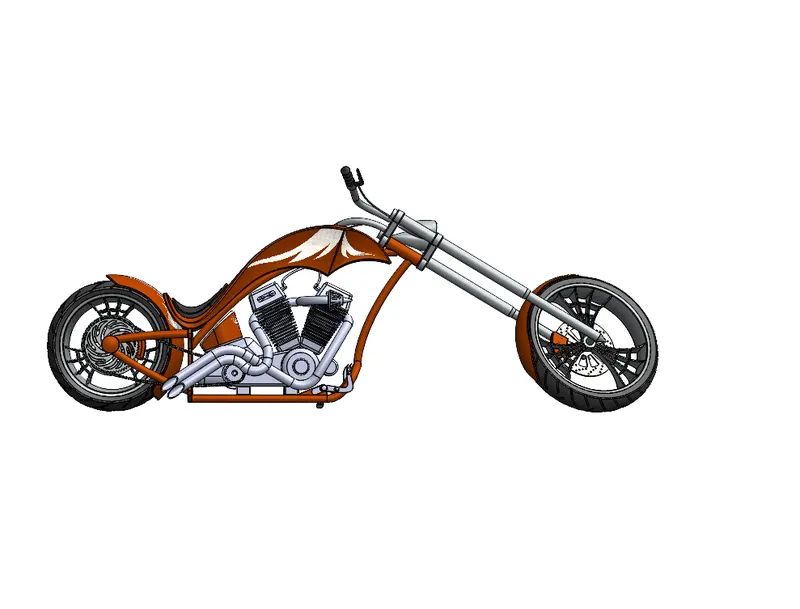
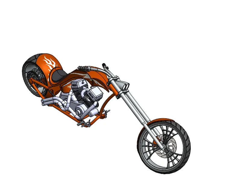
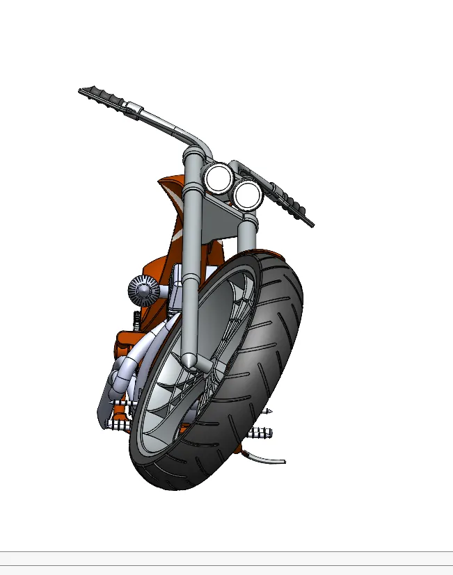
- now the gas tank is fixed with a distance mate and a parallel mate with respect to the chassis, the front fork is mated coincidently with the upper part of the chassis and a width mate is applied to retain the vertical motion of the fork now for the turning angle of the front part of the chopper an angle mate with certain limitations is applied with the fork and the chassis, finally the front wheel is attached with the front fork as it was attached in case of the rear wheel and the fender is placed above the front wheel as shown in the diagram.
RENDERING OF THE CHOPPER
In rendering, the chopper was made to set up in such a way to look natural and unique. Decals were added to the body parts. Views and light directions were changed. Using solidworks visualize, the appearances, background scenes and camera views were changed. Then final rendering was done to make the chopper, a cool and realistic one.
Conclusion
The parts of the chopper are modelled, assembled and rendered.