Roof challenge
ROOF DESIGN
OBJECTIVE:
- To design the automotive roof based on the given styling surface and to analyze the prepared model
to check the manufacturability and the feasibility of the design.
- To perform the section modulus study for the master sections and create for the front roof rail, rear
Roof rail, bow roofs, and center roof rail.
- To create the ditch area and to perform the draft analysis.
ROOF:
An automobile roof is the portion of an automobile that sits above the passenger compartment , protecting the vehicle occupants from sun, wind, rain, and other external elements.
The roof itself may be constructed of soft or rigid material. Soft-tops are made of vinyl,canvas, or other textile materials ; hard-top convertables have roofs made from steel, aluminium, plastic or carbon fiber composites. Your vehicle can also become ruined in an accident . Though a defect may seem insignificant at first , it can lead to serious consequences . Whether your roof was dented due to downfall or roughed up in a collision. It is urgently necessary to find a replacement for it. The roof panel is attached to the BIW of the car with the help of front and rear roof rails. This attachments is done with the help of sealants. Bow roofs 1and 2 are attached depending upon the length of the roof along with the central roof rail. Longer the roof more the number of roof rail. Other dimensions like strength and material is governed by the factors like head room, overall space , visibility, ergonomic and the rules and regulations of the states where it is sold.
DESIGN CONSIDERATIONS:
- Visibility criteria
- Head room clearance
- Curvature study
- Heat distortion and Snow load criteria
- Draft analysis
- Safety parameter
MATERIAL PROPERTIES:
Density :7890kg/mm3
Youngs modulus:210000Mpa
Poissons ratio: 0.3
Yield stress: 210 mpa
Metal roof mass: 11.2 kg
Thickness: 0.75mm
Joining process: metal roof with spotweld connectios.
COMPONENTS TO BE DESIGNED:
- Roof outer panel with necessary flanges and ditch area
- Front roof rail
- Rear roof rail
- Bow roofs
- Center roof rail
ROOF OUTER PANEL WITH NECESSARY FLANGES AND DITCH AREA:
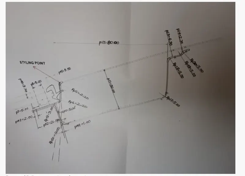
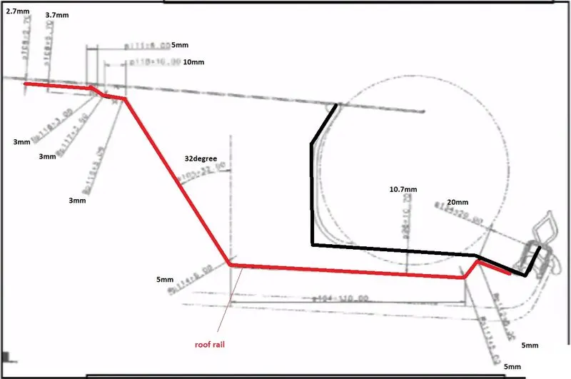
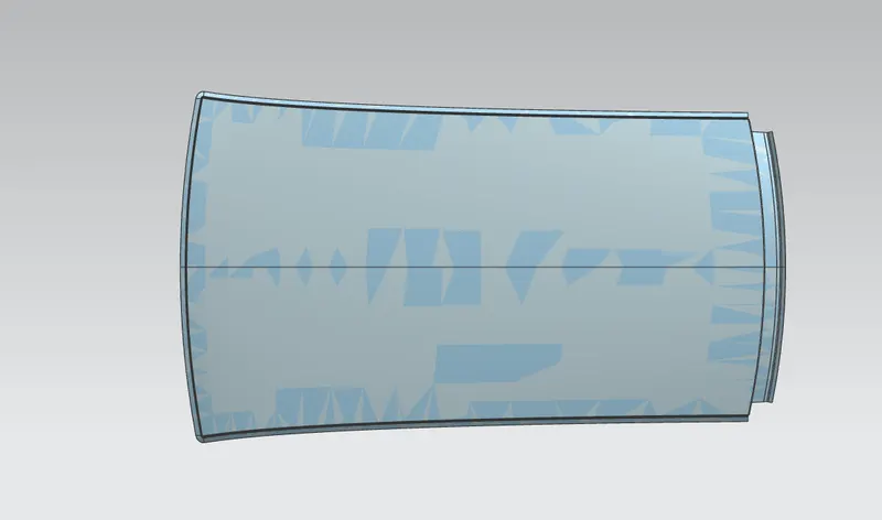
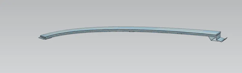
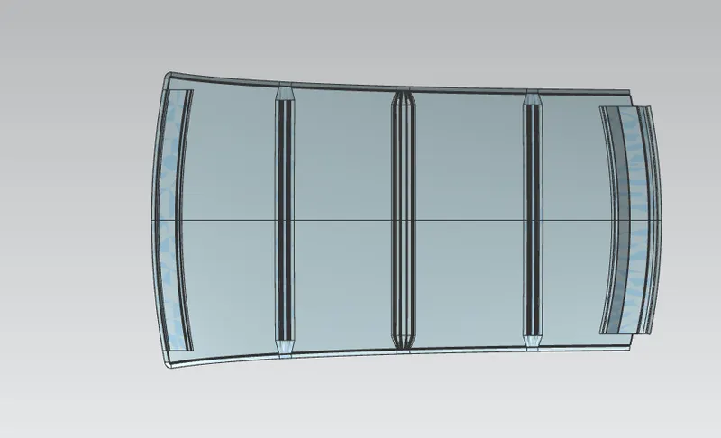
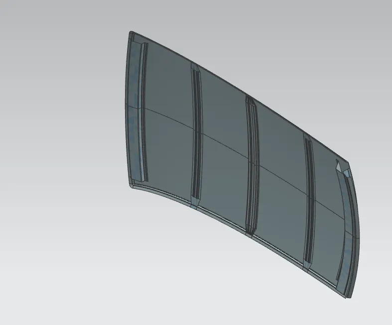
It is the extend portion of the main roof concealed by other BIW panels. The various roof rail supports mentioned above are attached to the ditch area using spot welds as it is not a styling surface viewed from outside. On other regions, rails are attached to roof using mastic sealants which also improves the NVH factors of the car. Headroom clearance , visibility criteria , clearance for wind shield and back door are some of the factors to be considered while designing the ditch area. The thickness is o.75mm , 4mm gap is maintained between roof panel and rail upper surface for mastic sealant application. Min 7 deg angle is maintained while creating flanges considering manufacturability of the part so that the tool can be pulled away from the object easily, without deformation or damage .
FRONT ROOF RAIL:
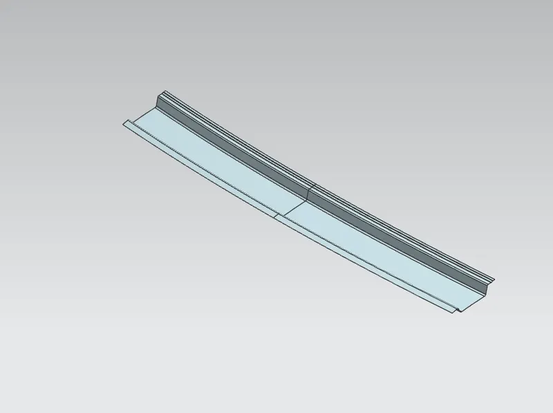
It is support that is joined with windshield glass , body side outer and inner panels. It is usually made from body side outer scarp and therefore the thickness of the rail is 0.75mm . A draft angle of 3 to 5 deg is provided for deep drawing operation . The visibility criteria and headroom clearance of the passengers are taken into consideration for the bottom most flange . Windshield end and the roof end are spot welded and the other end of the front roof rail is joined with the roof using mastic sealants for increased strength.
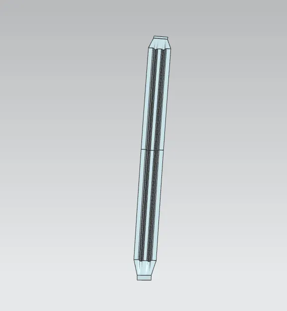
BOW ROOF 1:
Bow roof center1 is an additional stiffing member used in the roof assembly for the localised strength improvement and it is join directly to roof itself with several spot welding or even with mastic sealant.
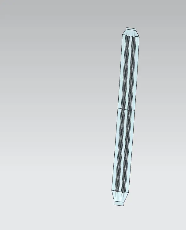
BOW ROOF2:
It is similar to that of bow roof 1 which serves the same purpose as the previous but with a limited extend and hence it is used with smaller cross.
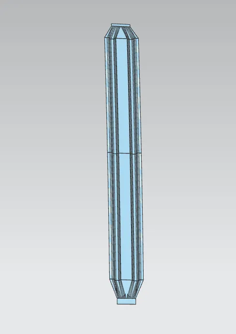
CENTER ROOF RAIL:
Center roof rail or reinforcement center is used as a cross member between bodyside left hand and right hand respectively. In some case the reinforcement center is not joined with the roof and in some other cases it is made to join in both roof and body side . The reinforcement center and bow roof are joined either spot weld or by mastic sealants.
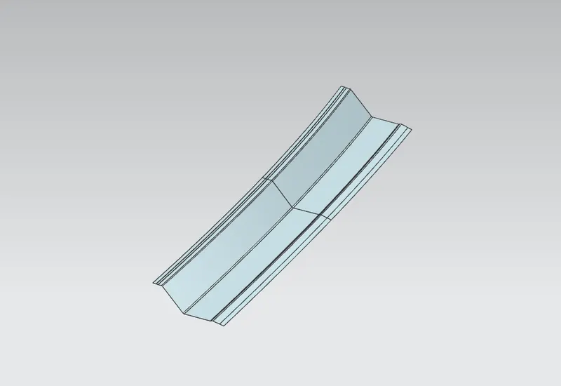
REAR ROOF RAIL:
Back door and the rear roof rail got attached here with the help of mastic sealants.
I maintained 0.75mm thickness for the rear roof rail because morethan 0.75 mm means increase in overall weight of the car.
This 0.75mm is perfect and standard thickness for the automotive sheet metal components.
It is support that is joined to the backdoor , the bodyside outer and the inner panels. Inputs from the backdoor design is also taken to consideration the required clearance along with headroom clearance and rear visibility criteria while designing the rear roof rail . Spot welds are applied at the backdoor end of the rail and other end is joined with the roof.
DITCH AREA:
It is the extended portion of the main roof by other BIW panels and not a styling surface. Headroom clearance , visibility criteria , clearance for windshield and back door are the some of the factors to be considered while designing the ditch area.
ANALYSIS:
- Curvature study – it is done to justify the positioning bow roofs. There are mainly 3 criteria to fulfill.
1.1 Heat distortion criteria
1.2 Snow load criteria 1.3 Roof crush test
- Section modulus
- Draft analysis
HEAT DISTORTION
W = 1.73 ×10^-3 × L +1.85×10^-8 ×(R^2)/t +1.10×10^-3×l -2.68
Where
L= roof length in x-direction in mm (roof dimension in 0-Y)
R= Roof curvature
R= 2(Rx*Ry)/(Rx +Ry)
Rx= X curvature
Ry= Y curvature
T =thickness ,l= Bow roof span in mm
Judgement condition ok <2.7mm>3.1
|
Sl no |
BOWS |
t |
Rx |
RY |
R |
l |
L |
W |
OK/NG |
|
1 |
FR &BW1 |
0.75 |
5733.4825 |
1895.2319 |
2848.7837 |
391.3546 |
2025.8905 |
1.45 |
OK |
|
2 |
BOW1&CR |
0.75 |
4932.9491 |
6355.6992 |
5554.666 |
405.8438 |
2025.8905 |
2.03 |
OK |
|
3 |
CR&BOW2 |
0.75 |
3037.1859 |
10847.4716 |
4745.637 |
449.9664 |
2025.8905 |
1.87 |
OK |
|
4 |
BOW2&RR |
0.75 |
3254.6298 |
7010.3089 |
4445.414 |
288.2958 |
2025.8905 |
1.629 |
OK |
Thus all values of W <2.7 So according to heat distortion criteria current positioning of all the bow roofs are found ok.
SNOW LOAD PREDICTION FORMULA:
Qr= (Iy×t^2) / (α× s × (Rx + Ry )/2)^2×10^-8
Judgement condition Qr≥ 3.1
Where α= My × Lx^2 × 10^-12 , My= Y (Ly-Y)
250≤ s ≤ 380
T= roof thickness
Ly= distance between the front and rear roof rails on the vehicle along with OY in mm.
Lx= distance between the left and right end of the roof on the roof bows in mm
Y= distance from front roof rail to bow roof in mm
S= distance for which bow bears divided load in mm , s= L1/2 + L2/2
Iy = geometrical moment of inertia of bow roof mm4
Rx= lateral direction curvature radius of roof panel Y cross section on roof bow in mm
Ry= longitudional direction curvature radius of the roof panel x cross section on bow roof in mm
|
Sl no |
Bows |
α |
My |
Lx |
Y |
Ly |
S |
L1 |
L2 |
|
1 |
FR & B1 |
0.81506 |
634811.076 |
1133.1127 |
387.448 |
2025.890 |
478.1875 |
387.448 |
405.741 |
|
2 |
B1& CR |
0.77099 |
657360.875 |
1082.991 |
405.741 |
2025.890 |
427 |
405.741 |
449.671 |
|
3 |
CR&B2 |
0.78833 |
708779.9739 |
1054.6258 |
449.671 |
2025.890 |
368.687 |
449.671 |
287.703 |
Snow load criteria
|
SL NO |
BOWS |
Iy |
α |
s |
Rx |
Ry |
t |
Qr |
OK/NG |
|
1 |
FR&B1 |
485 |
0.81506 |
478.1875 |
4477.652 |
2677.951 |
0.75 |
5.4 |
OK |
|
2 |
B1&CR |
216 |
0.77099 |
427 |
3772.326 |
6267.771 |
0.75 |
3.34 |
OK |
|
3 |
CR&B2 |
495 |
0.78833 |
368.687 |
4298.394 |
11421.359 |
0.75 |
1.55 |
NG |
MOMENT OF INERTIA
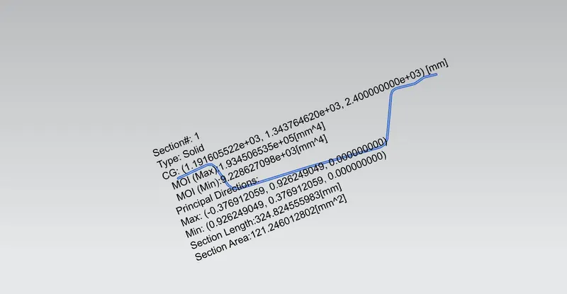
FRONT ROOF RAIL
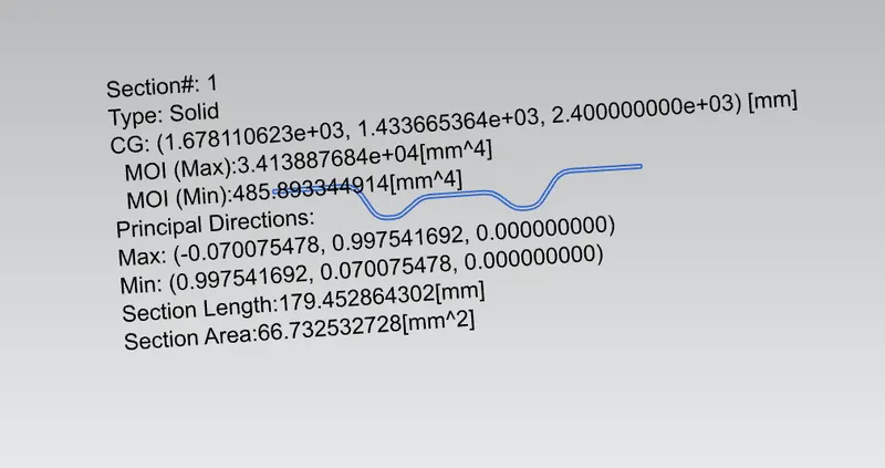
BOW ROOF 1
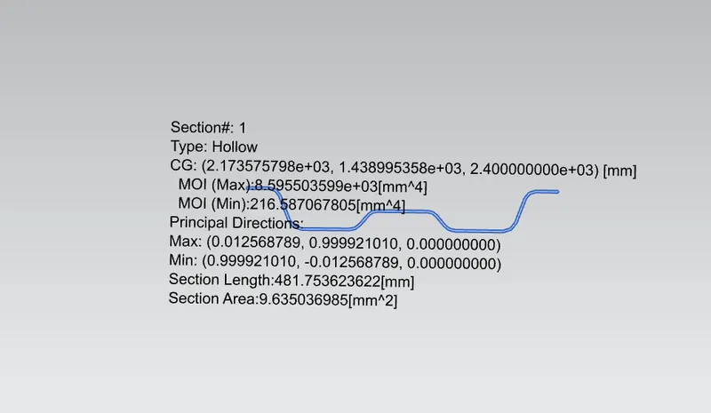
CENTER ROOF RAIL
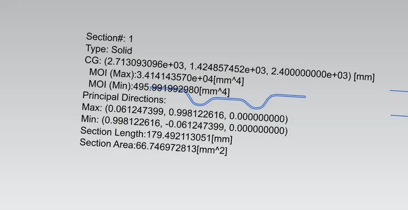
BOW ROOF 2
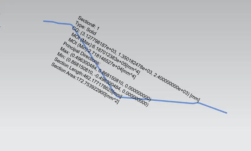
REAR ROOF RAIL
SECTION MODULUS
Section modulus is a geometrical property for a given cross section used in the design of beams. There are two types of section modulus , the elastic modulus and the plastic section modulus. For general design the elastic section modulus is used, applying up to the yield point for most metals and other common materials.
The elastic section modulus is defined as S=I/y
FRONT ROOF RAIL
S=I/y
= 9.228627098e+03/68.111 = 368.310mm3
BOW ROOF RAIL1
S= I/Y = 485.893344914/40 = 12.147MM3
CENTER ROOF RAIL
S= I/Y = 216.587067805/50 = 4.33MM3
BOW ROOF 2
S= I/Y = 495.991992980/40 = 12.399MM3
REAR ROOF RAIL
S = I/ Y = 2.718146527e+04/ 104.7 = 25.999mm3
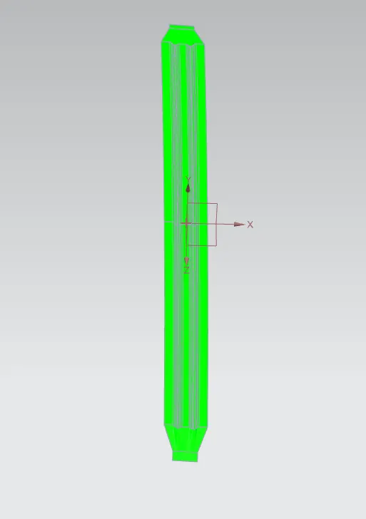
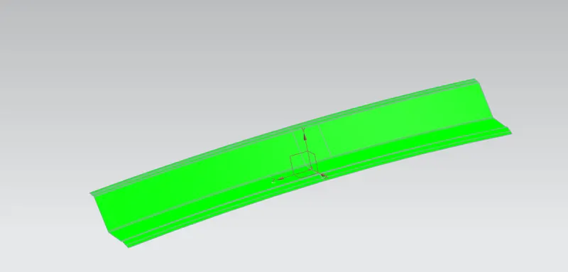
DRAFT ANALYSIS
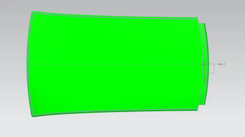
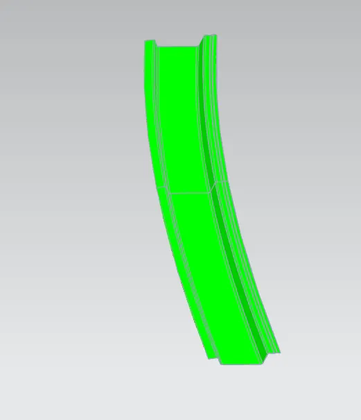
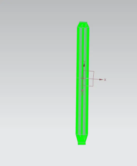
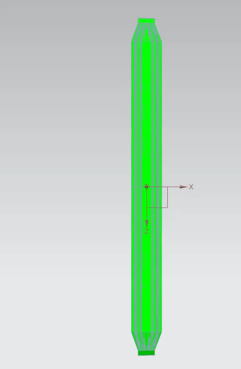
Draft analysis is performed to check whether the part can be ejected from the tool so that it is manufacturable. Here I provide a min draft angle of 7 deg for all parts.
ROOF OUTER
FRONT ROOF RAIL
BOW ROOF 1
CENTER ROOF RAIL
BOW ROOF 2
REAR ROOF RAIL
CONCLUSION
Thus the roof outer panel and its reinforcement rails were designed using NX CAD . At first with the given roof styling surface , I developed the outer panel with essential flanges on the ditch area, reinforcement such as front roof rail, two bow roofs, center roof rail with an inner bow roof and rear roof rail with appropriate dimensions. Then checked the draft analysis and found the section inertia in OY section and also did a curvature study and necessary calculations.