Photo Realistic Rendering
DESIGN AND ASSEMBLY OF AMERICAN CHOPPER IN SOLIDWORKS
OBJECTIVE
Design and Assembly of an American Chopper (Rt66 Chopper) in Solidworks 2019 by using
various tools and feature and Rendering the model using Solidworks Visualize.
INTRODUCTION
Solidworks is an CAD software used to design any 3D object which is extruded from fully defined
2D sketches and geometries. The software was developed by DASSULT SYSTEMS located in VelizyVilacoublay, France. The aim of the software is to create solid bodies through it has various tools such as
surface modelling , sheetmetal modelling, photo view 360 and more. It is finest and user friendly
software which allows us to get through the features and tools quickly. Here , we were going to
overview and research various tools and feature used in designing the Rt66 chopper bike.
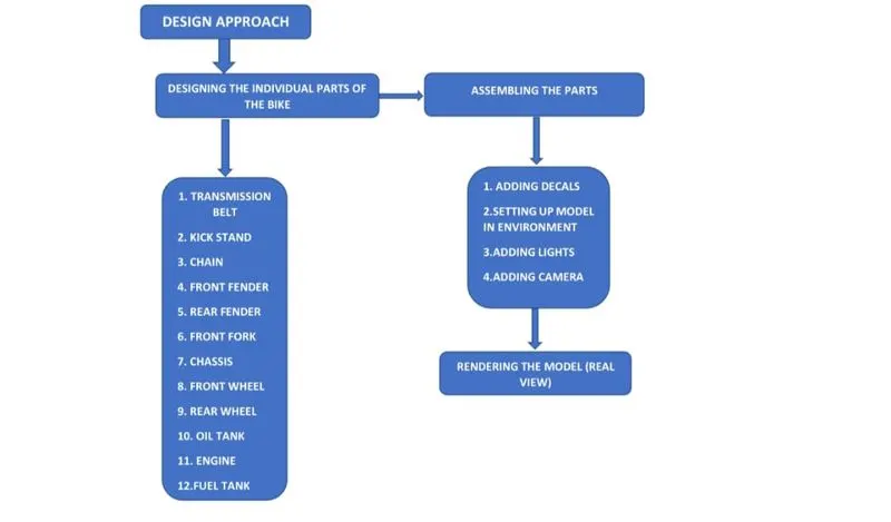
DESIGN METHODOLOGY
SKETCH
Sketch is a two dimensional representation for converting 2D sketch to 3D modelling. In solidworks ,
there are different sketch options to create a sketch and these are known as sketch entities – lines,
circles ,arc , rectangle etc.
EXTRUDE BOSS
This feature is to convert 2D into solid modelling only when the 2D sketch is completely closed. It also
allows to extrude the surface in both directions and also offset is to require distance.
FILLETS
This is to create a radius on the profile edges on solid model by selecting the required lines or the
faces . The fillet also has a feature to select multiple lines at a single click.
EXTRUDE CUT
This command is used to remove materials from a solid model in desired pattern and it can be cut in
both directions .
SPLIT TOOLS
This command is used when two or more solid bodies intersect each other then split tool allows to
delete unwanted solid bodies and gives a clean look.
TRIM ENTITIES
There are three types of Trim entities
1. Extend entities – Which allows the line to extend upto the next line and intersect and can be
done only in 2D sketch.
2. Trim entities – This command is used to remove the unwanted lines which are intersecting to
each other.
SWEEP SURFACE
Surface generated from section curve positioned along the path.
CHAMFER
It is similar to the fillet feature but in chamfer , it cuts the solid model intersection area into recutted
length and angle.
COMBINE
Combine feature is used to combine two or more bodies when intersecting to each other and make
it a single body.
MODELLING OF INDIVIDUAL PARTS
TRANSMISSION BELT
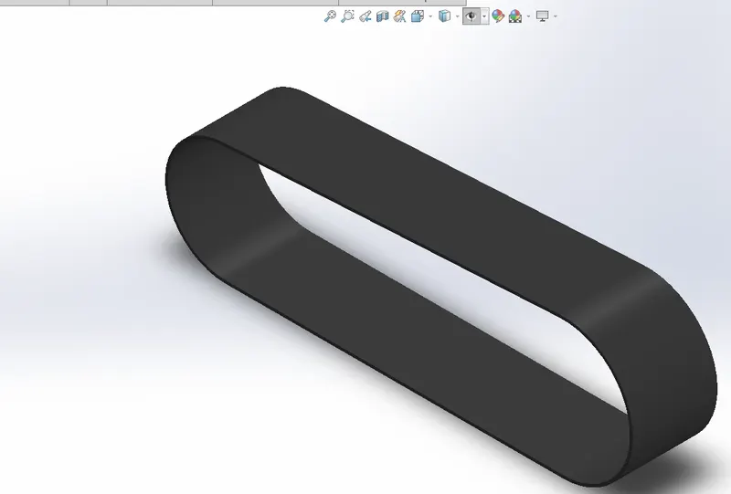
This is used to transmit power from engine to gear box.
Feature used to create transmission belt
- Sketch
- Offset
- Extrude
- Fillet
- Appearances
FRONT FENDER
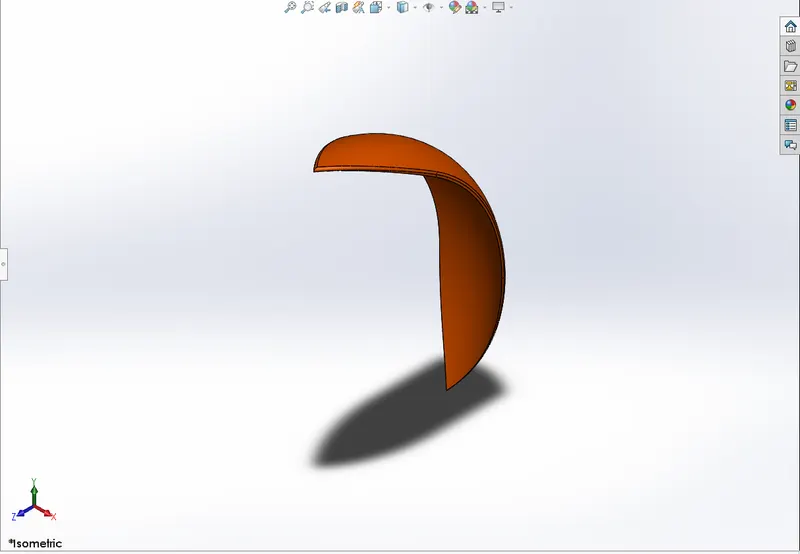
The front fender is mounted on the front fork above the wheel to protect the rider and chopper from
mud and other particles.
Features used to create front fender
- Sketch
- Revolve
- Split
- Fillet
- Appearances
REAR FENDER
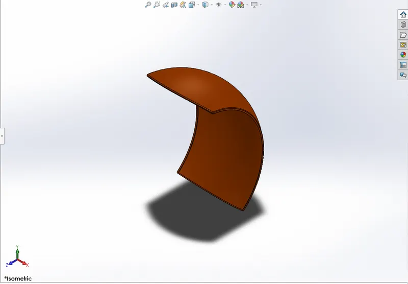
The working principle of rear fender is same as front fender. The rear fender is mounted above the
rear wheel.
Features used to create rear fender
- Sketch
- Revolve
- Split
- Fillet
KICK STAND
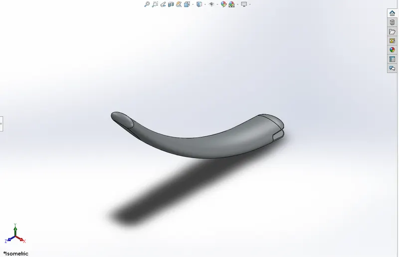
It is also known as side stand . It is used to support the chopper while it needs to rest on the ground.
Features used to create kick stand
- Sketch
- Loft
- Dome
- Extrude cut
- Extrude boss
- Split
- Fillet
CHAIN
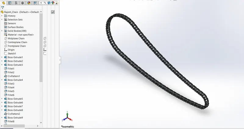
Chain is used to transmit the power from the engine to the rear wheel .
The features used to create chain
- Sketch
- Trim
- Fillet
- Blocks
- Extrude
- Ptterns
- Appearences
OIL TANK
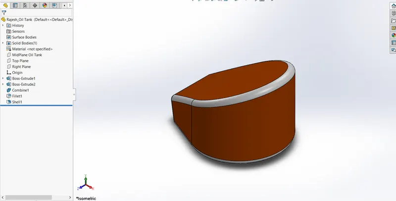
The oil tank is used to store the oil required to run the engine .
The features used to create oil tank
- Sketch
- Boss extrude
- Fillet
- Combine
- Shell – Shell is used to remove the inner region of solidbodies and make it hollow. It creates open
shell and closed shell as well.
PEDAL
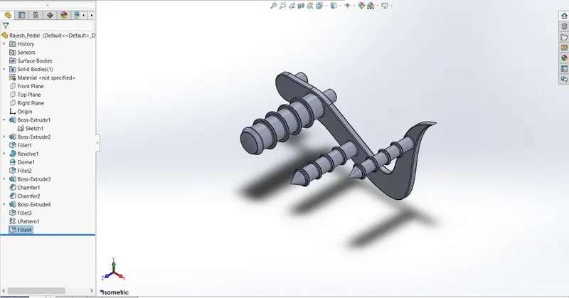
Pedal is the external part attached to the chassis. The pedal is used to place the leg on the top of
that to give comfort to the rider.
Feature used to create pedal
- Sketch
- Extrude
- Fillet
- Linear pattern
- Dome
- Chamfer
FRONT WHEEL
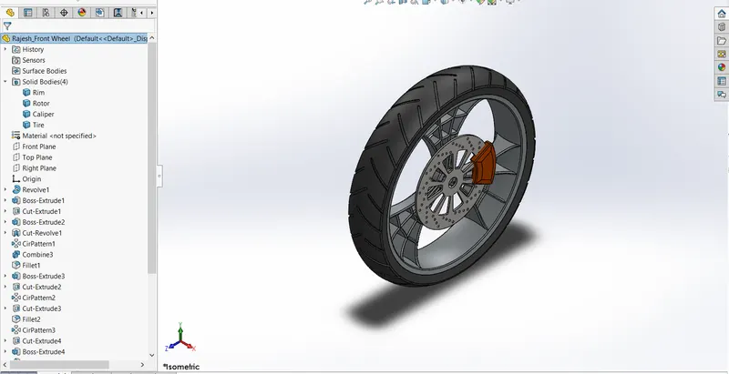
A wheel is a circular block made of alloy . On the top of wheel , tyre is covered.
Features used to create front wheel
- Sketch
- Revolve
- Trim
- Fillet sketch
- Boss extrude
- Revolve cut
- Linear pattren
- Chamfer
- Cut extrude
- Circular pattern
REAR WHEEL
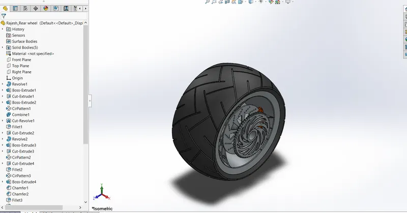
A circular object that revolves on an axis and is fixed below a vehicle or other enabling it to move
easily over the ground.
The disc and sprocket are attached with rear wheel.
The chain is connected between engine and the rear wheel.
Features used to create rear wheel
- Sketch
- Revolve
- Trim
- Fillet
- Boss extrude
- Planes
- Revolve cut
- Linear pattern
- Chamfer
- Circular pattern
FRONT FORK
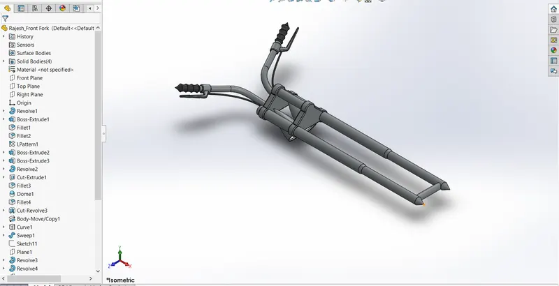
Most of the bikes used telescopic front suspension. The fork can be most easily understood as
simply large hydraulic shock absorber with inner coil spring.
Feature used to create front fork
- Sketch
- Extrude
- Trim
- Revolve
- Split
- Move
- Combine
- Projected curve
- Sweep
CHASSIS
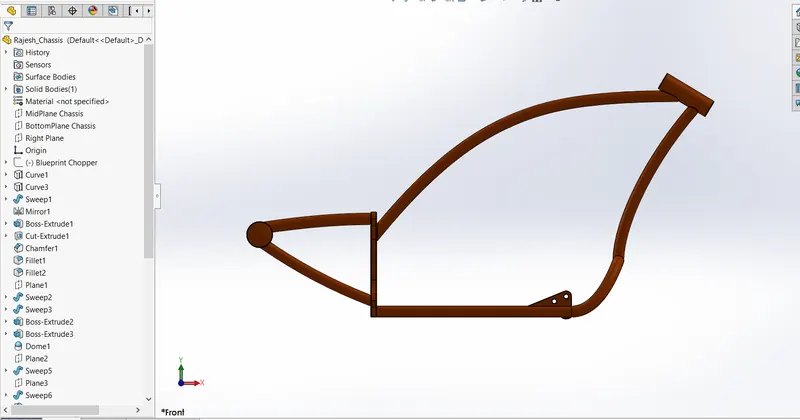
It is frame forms its skeleton . All the components of chopper are mounted to this base structure which
tends a chopper its strength and ability to handle well.
Feature used to create chassis
- Sketch
- Offset
- Convert entities
- Projected curve
- Trim
- Sweep
- Split
- Revolve
- Extrude cut
- Fillet
- Combine
ENGINE
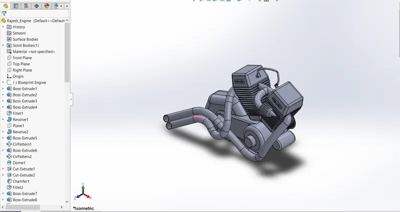
Engine is the prime mover for the bike.
The engine converts a chemical energy into the heat energy and then heat energy is converted to
mechanical work.
The mechanical work in the engine is a rotational motion.
The rotation is transmitted to wheel with the help of chain and sprocket through the gear box and
clutch.
Features used to create engine
- Sketch
- Trim
- Revolve
- Boss extrude
- Extrude cut
- Offset
- Dome
- Fillet
- Projected curve
- Composite curve
- Sweep
- Mirror
- Circular pattern
- Split
GAS TANK
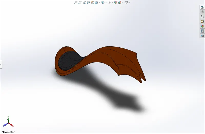
Gas tank is used to store gas and gives to engine when required.
Features used to create gas tank
- Sketch
- Trim
- Projected curve
- Sweep surface
- Loft surface
- Fill surface
- Surface trim
- Sweep cut
- Fillet
ASSEMBLY OF CHOPPER
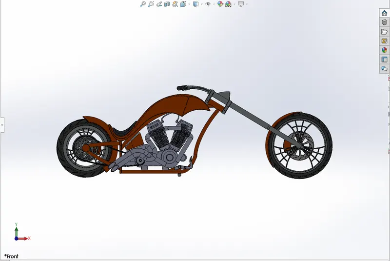
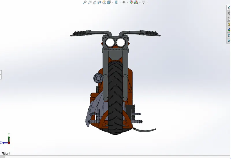
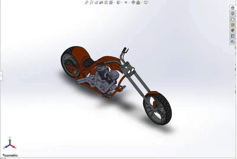
Assembling of bike starts after completing the design of individual parts. In the assembly , the chassis
of the bike is mounted initially , and other parts are assembled with relation to the planes of chassis
to follow up. The image of complete assembled bike is attached below.
Features used to create assemble chopper
- Inserting parts
- Mates
ADDING DECALS TO THE PARTS
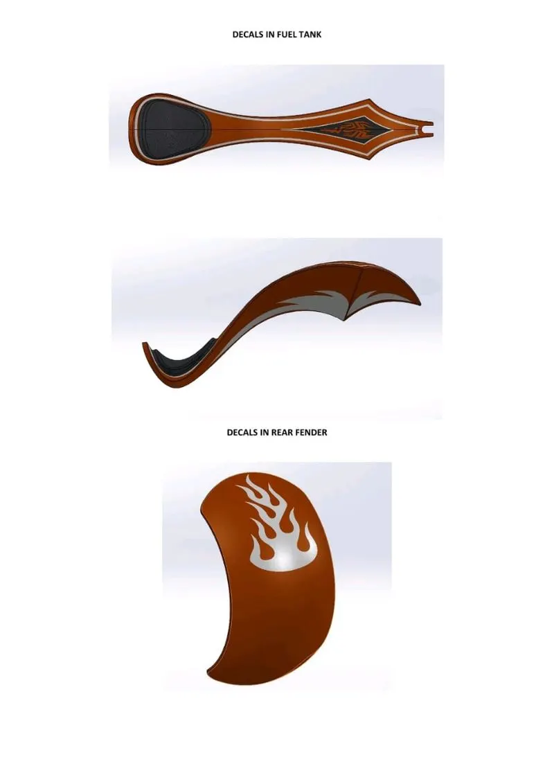
PHOTOVIEW 360
Photo view 360 is a visualization and rendering solution includes with solidworks. Providing a highly
interactive environment for viewing design as well as for creating photo realistic rendering .
SOLIDWORKS VISUALIZE
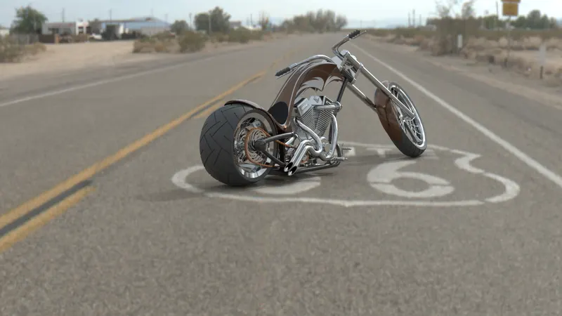
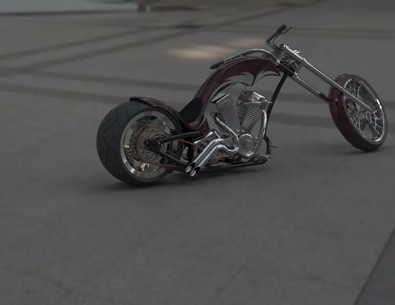
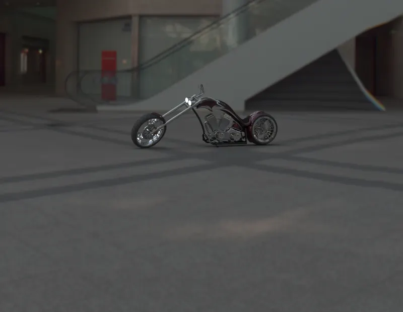
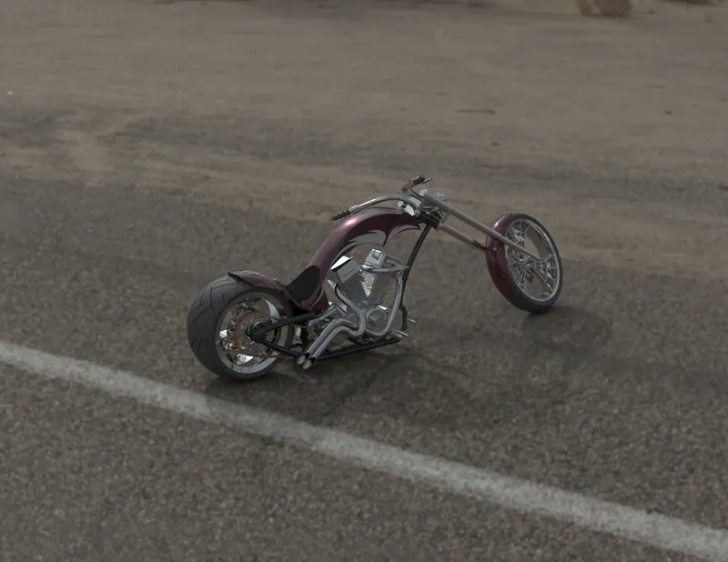
Solidworks visualize software tool that combine industry leading rendering capabilities with usual
design oriented features and workflows.
CONCLUSION
In the overall project of designing the american chopper bike, I had learned many unexplored features
and tools which needs to be applied wherever necessary. From sketching to rendering the final image of
the bike, the detailing and steps to generate the perfect output was challenging and faced many
mistakes and flaws which directs me to the complete design the project.
THANK YOU!
PROJECTED BY
P. RAJESHPATRA