Roof challenge
ROOF DESIGN
INTRODUCTION
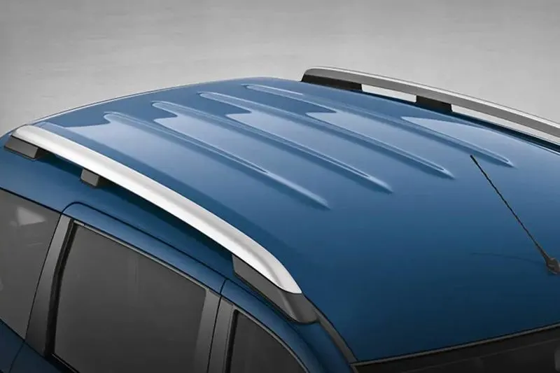
The objective is to design a roof with the essential flanges and reinforcements using the provided roof styling. Also perform the draft analysis, section inertia calculation, heat distroction and snow load calculations.
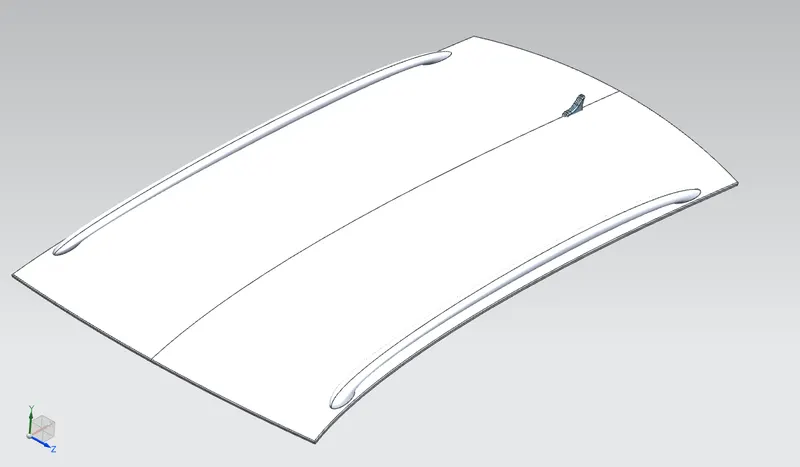
An automobile roof or car top is the portion of an automobile that sits above the passenger compartment, protecting the vehicle occupants from sun, wind, rain, and other external elements.
Design Conditions
- Visibility for the driver ahead
- Head clerance for the occupants
- Ease of maufacturing
- Crush resisting criteria
- Hear distortion
- Snow load criteria
Software used : SIEMENS NX 12
PART DESIGNS
Front Roof Rail
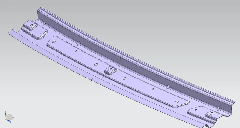
It the part which act as a reinforcement for the front part of the roof. With its embosses it can strengthen the roof. There are holes given for the wiring for the lights. It is fixed with the roof outer panel using spot welding it on the front flange.
Bow Roof Rail 1
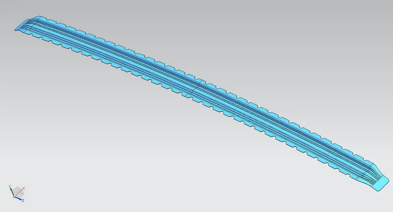
It is the part after the front roof rail. Bow roof rail is a part which is placed intermediately with the front roof rail and rear roof rail. It extends from both the side flanges and is fixed with help of spot welding. A array of flanges is given along the length side of the bow to apply mastics.
Centre Reinforcement Roof Rail
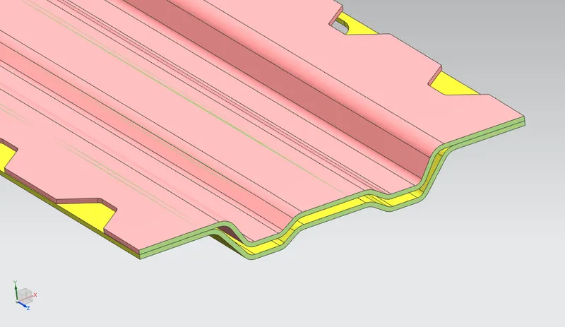
It is the part which has more strength that the bow roof rails. It is usually positioned at the centre of the roof and consist of a smaller bow roof at the inner part of the rail. The inner bow roof has the mastic flanges and the outer roof rail has the flanges to be spot welded on to the roof outer panel flange. Both the rails are also spot welded.
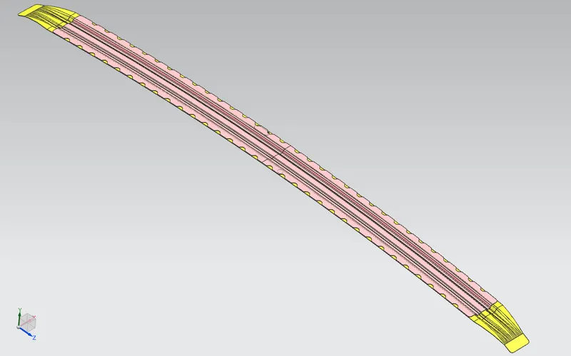
Section View
Bow Roof Rail 3
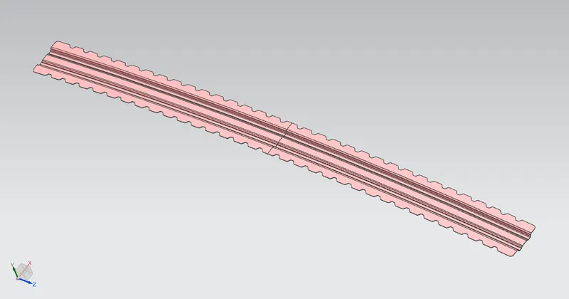
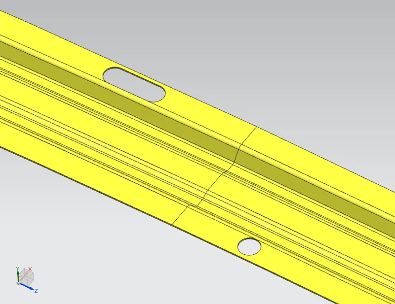
Outer Centre Roof Rail
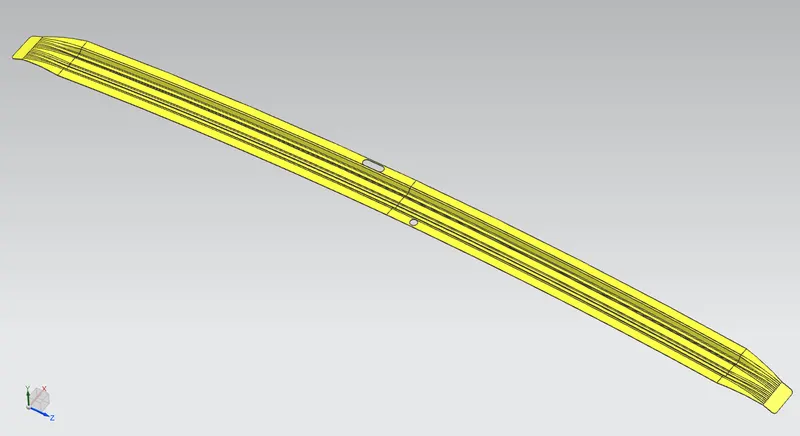
Slot and a hole is given to the rail to fix roof lamps.
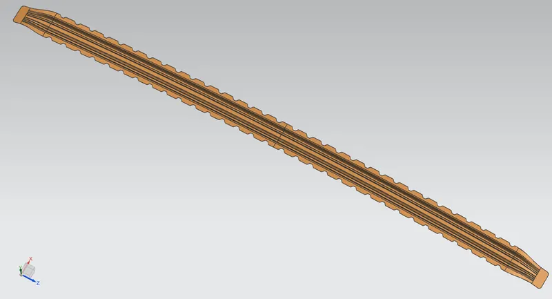
Bow Roof Rail 2
It an additional bow roof in between centre and rear roof rail. It also has mastic flanges to be fixed on to the roof outer panel.
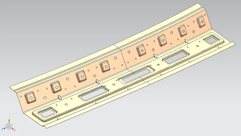
Rear Roof Rail
Just like front roof rail it is a reinforcement structure for the rear of the roof outer panel. It is designed so that there is adequate space back door could swing at its axis. It also has embosses for strength and holes for the wiring.
Roof Outer Panel
This part is created after extracting a surface from the styling roof panel and then it was untimmed to get the original surface.
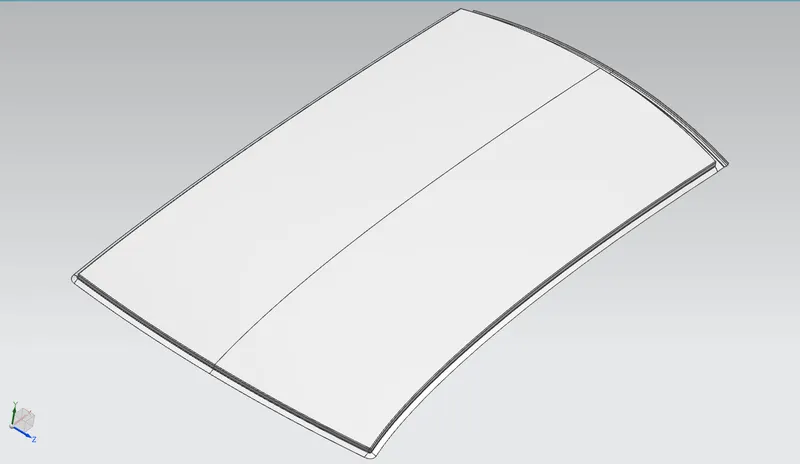
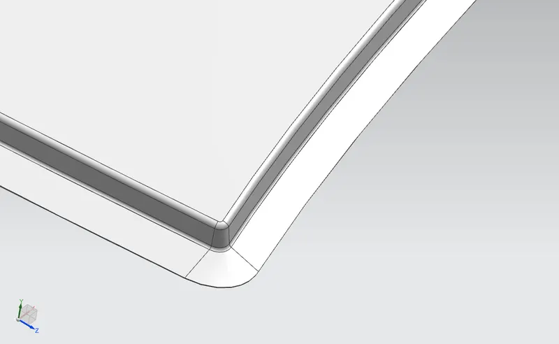
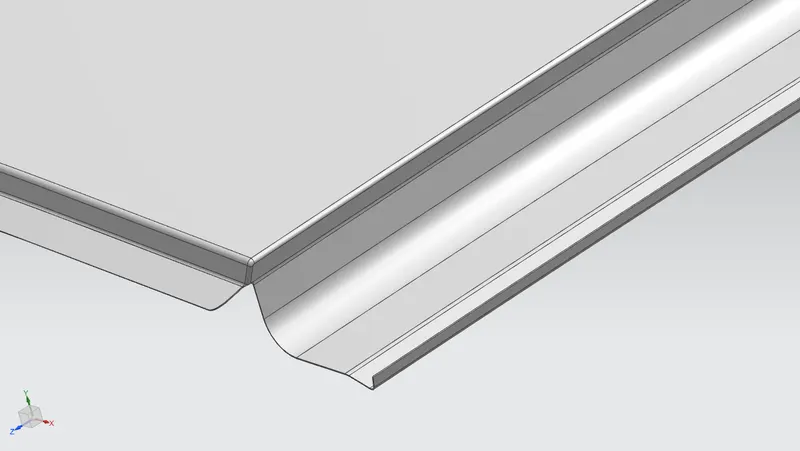
Flanges are created to attach the bow roofs and to acconmodate the back door.
Front and Side Flanges
Rear Flange
ROOF CALCULATIONS
Heat Distorsion Calculation
Equation
W = [1.73 x 10^(-3) x L] + [1.85 x 10^(-8) x (R^2)/t] + [ 1.10x10^(-3) x l] - 2.68
Judgement condition: OK<2.7>3.1
Where,
L = Roof length in X-direction(mm) (Roof dimension in 0-Y)
R = Roof curvature = 2(Rx*Ry)/(Rx+Ry)
Rx = X Curvature
Ry = Y Curvature
t = Roof plate thickness(mm)
l = Bow roof span(mm)
Except Rx and Ry, all values can be measured on the model.
To get Rx and Ry curvature, a sketch is required,
- A sketch was created on a plane on top of the roof
- 0-Y line was created in the X-Direction in center of roof
- Then a horizontal line below 300mm was created named as -3Y line
- Two lines on both sides at 100mm were created from -3Y line
- Intersection point on line was created and projected on outer panel of roof.
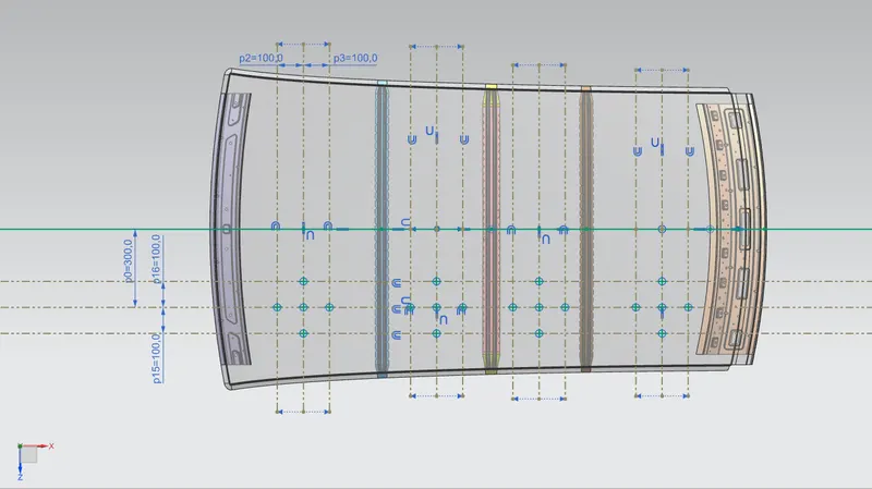
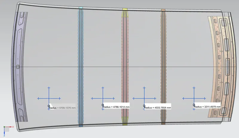
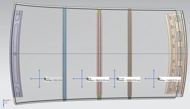
The points are projected on to the roof outer panel and arcs are created using three point arc tool.
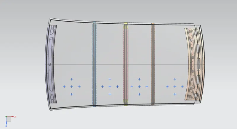
Minimum Radius of Curvature Value at Rx1, Rx2, Rx3, Rx4
Minimum Radius of Curvature Value at Ry1, Ry2, Ry3, Ry4
| SL NO: | BOWs | Rx | Ry | R | t | l | L | R^2/t | W | OK/NG |
| 1 | Front - Bow Roof Rail 1 |
5709.3 |
2892.06 | 3839.27 | 0.75 | 521.15 | 2028.38 | 19653325.51 | 1.765948 | OK |
| 2 | Bow 1 - Centre Roof Rail | 4786.10 | 6945.61 | 5667.09 | 0.75 | 360.65 | 2028.38 | 42821212.09 | 2.018004 | OK |
| 3 | Centre - Bow Roof Rail 2 | 4033.76 | 10296.37 | 5796.60 | 0.75 | 305.82 | 2028.38 | 44800762.08 | 1.994346 | OK |
| 4 | Bow 2 - Rear Roof Rail | 3311.49 | 14382.81 | 5383.48 | 0.75 | 447.66 | 2028.38 | 38652475.88 | 2.036409 | OK |
The W values satisfyes the condition OK<2.7>3.1,
So all the values are OK.
Snow Load Condition
During winter season the snow gets clogged over the top surface of the car and the snow has some mass. Due to this , the roof can fall if the snow load exceeds the capacity of the roof that was designed to sustain.
Equation
Qr = [Iy x t2] / [α x s x [(Rx + Ry)/2]2 x 10-8]
Where
α = My x Lx2 x 10-12 , My = Y(Ly-Y)
Judgement condition = Qr ≥ 3.1
250 ≤ s ≤ 380
t = Roof plate thickness(mm)
Ly = Distance between the front and rear roof rails on the vehicle along with 0Y(mm)
Length of Roof panel with the center point between Roof rail Front /Rear as the front and rear reference point.
Lx = Distance between the Left and Right end of the roof on the Roof BOW [mm]
Width of the roof panel exposed on the surface.
Y = Distance from Front Roof Rail to Roof BOW[mm]
s = Distance for which Roof BOW bears divided load [mm]
s = L1/2 + L2/2
Iy = Geometrical moment of inertia of Roof BOW (Y cross-section )[mm4]
Rx = Lateral direction curvature radius of roof panel Y cross-section on Roof BOW [mm]
Roof panel curvature Radius of the Length Lx in Front view
Ry = Longitudinal Direction curvature radius of the Roof panel X cross-section on Roof BOW [mm]
Roof panel X curvature radius of length s in Side view
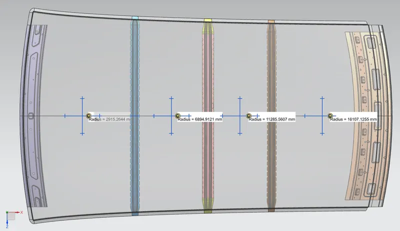
To get the values a sketch was created on top of roof
- 0-Y line was created in the centre of roof
- A line between first and centre roof rail was created
- Then two lines on both sides at 100mm was created
- Similar lines were created between other centre roof rail, both bow roof rails and rear roof rails
- Intersection points were created and projected on the roof
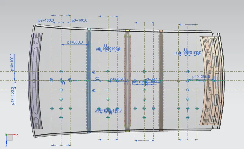
The points are projected on to the roof outer panel and usiing the three point arc tool arcs are drawn in X and Y direction with help of these projected points.
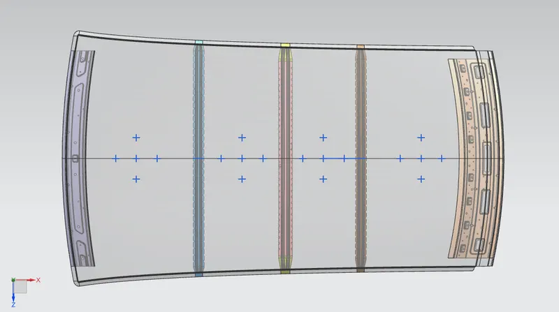
Minimum Radius of Curvature Value at Rx1, Rx2, Rx3, Rx4
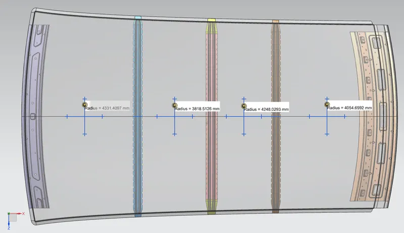
Minimum Radius of Curvature Value at Ry1, Ry2, Ry3, Ry4
| SL NO: | BOWs | Iy | α | Lx | Ly | Y | s | Rx | Ry | t | Qr | OK/NG |
| 1 | Front to Bow 1 | 18.77 | 1.09 | 1127.99 | 2028.38 | 600.25 | 509.88 | 4331.40 | 2915.26 | 0.75 | 1.4470267E-17 | NG |
| 2 | Bow 1 to Centre | 38.07 | 0.78 | 1078.40 | 2028.38 | 419.53 | 392.05 | 3818.51 | 6894.91 | 0.75 | 2.425232311E-17 | NG |
| 3 | Centre to Bow 2 | 18.96 | 0.67 | 1057.57 | 2028.38 | 364.58 | 471.01 |
4248.02 |
11285.56 | 0.75 | 5.533013977E-18 | OK |
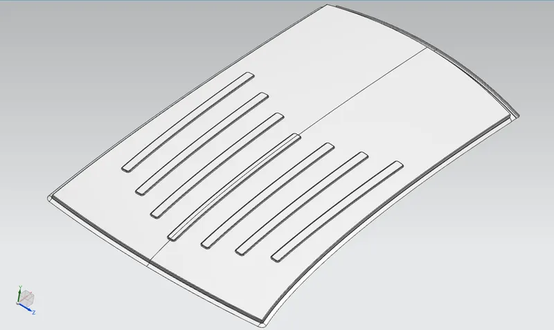
According to the judgement condition Qr ≥ 3.1 only the value between the centre roof rail and bow roof rail 2 satisfies. The reason why there is no value between bow roof 2 and rear roof rail is because there is no L2 value to apply in the equation for finding s. The values between front roof rail and bow roof rail 1, bow roof rail 1 and centre roof rail is below 3.1 so embosses are created to rectify the lack of snow load bearing capacity. Embosses improve strength. Other than creating embosses we can increase the thicknesses of the roof rails and bows. This will improve the minimum moment of inerta.
Section Modulus
Section modulus is a geometric property for a given cross-section used in the design of beams . Other geometric properties used in the design include an area for tension, radius of gyration for compression, and moment of inertia for stiffness. The section modulus is defined as
S= I/Y
S = Section Modulus
i = Moment of inertia
Y = Distance from the neutral axis to any given part.
Front Roof Rail
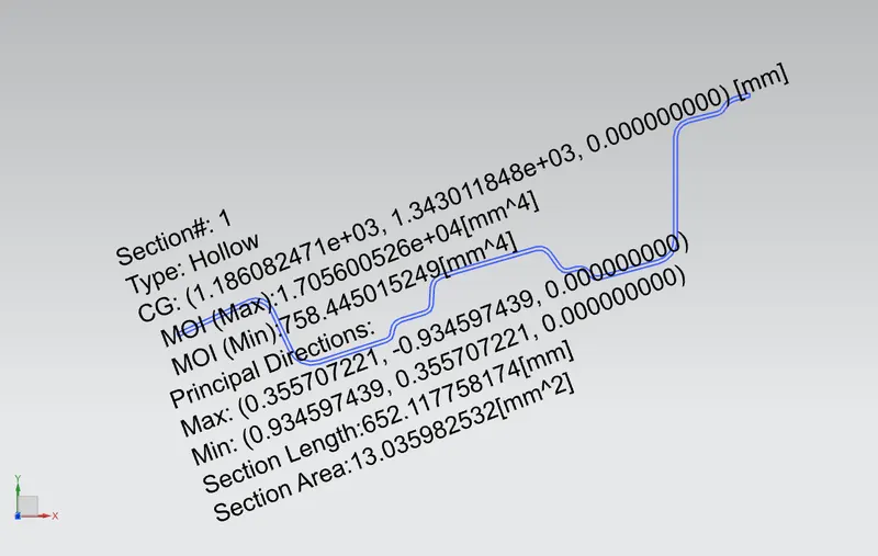
i (Min) = 758.445 mm4
Y = 123.983/2 = 61.991 mm
S = 12.234 mm3
Bow Roof Rail 1
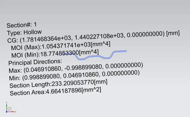
i (Min) = 18.774 mm4
Y = 51.941/2 = 25.97 mm
S = 0.722 mm3
Center Reinforcement Roof Rail
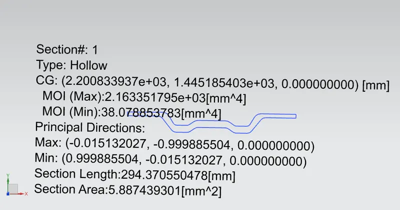
i (Min) = 38.078 mm4
Y = 65.951/2 = 32.975 mm
S = 1.154 mm3
Bow Roof Rail 2
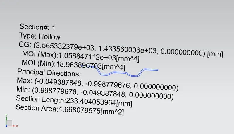
i (Min) = 18.963 mm4
Y = 51.976/2 = 25.988 mm3
S = 0.729 mm3
Rear Roof Rail
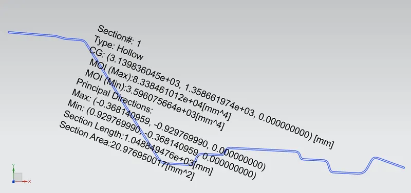
i (Min) = 3.596 mm4
Y = 221.373/2 = 110.689 mm
S = 0.0324 mm3
Draft Analysis
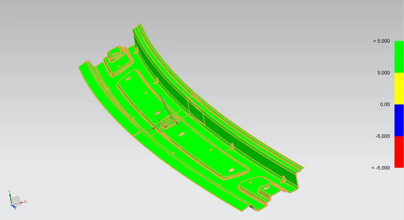
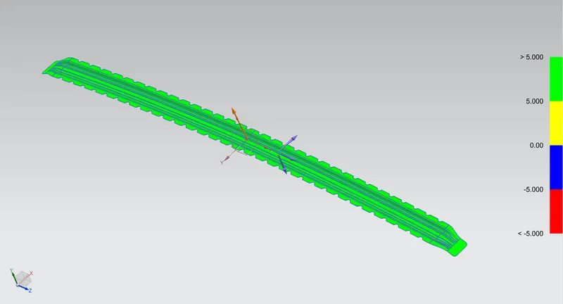
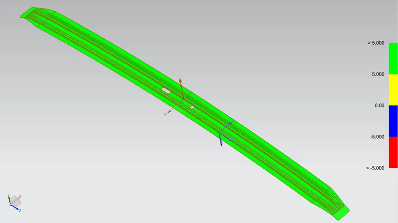
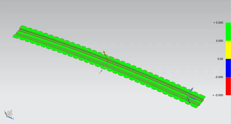
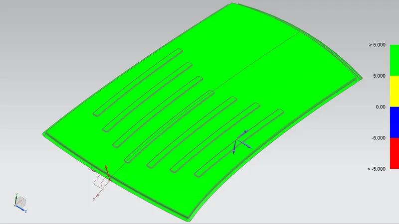
Draft analysis was performed with 5 degree value.
Front Roof Rail
Bow Roof Rail 1
Centre Reinforcement Roof Rail
Bow Roof Rail 3
Bow Roof Rail 2
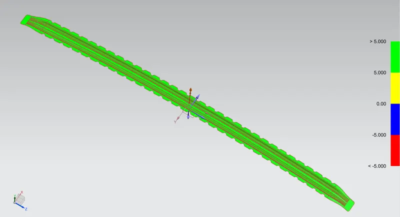
Rear Roof Rail
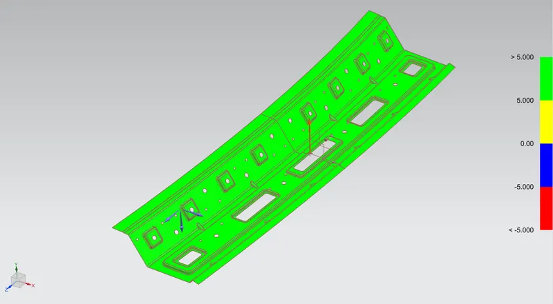
Roof Outer Panel
ROOF TESTING
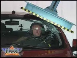
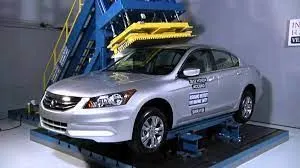
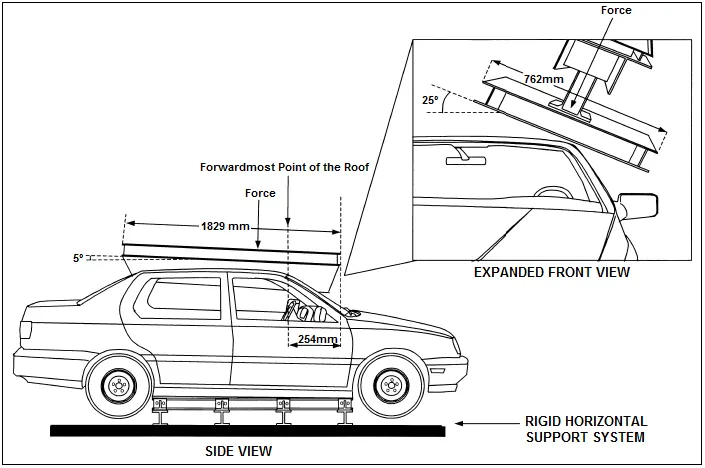
Mostly after the designing, calculations and design improvements we will perform destructive testing. In the real word conditions, there will be snow load, rail load, possibilities of trees falling on to the roof and roll-over accidents. In these all conditions the roof should resist these forces and prevent deformation thus ensuring safety of the occupants.
- Roof Crush Test
ROOF ASSEMBLY VIEWS
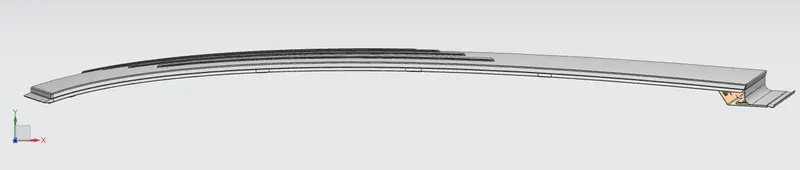
View after the roof outer panel is made transparent
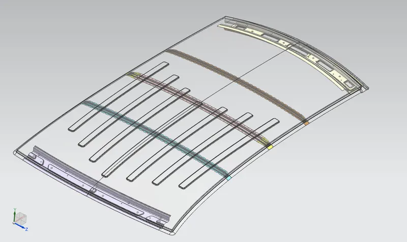
Front View
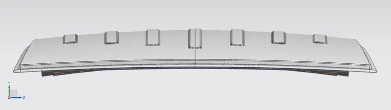
Side View
Top View
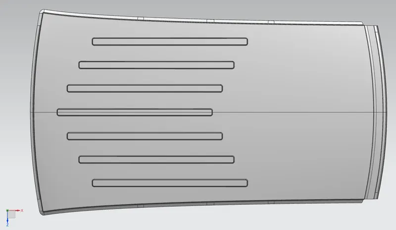
Bottom View
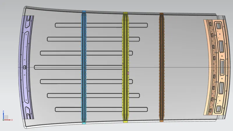
CONCLUSION
The roof was designed in Siemens NX 12 using the provided sityling model and the necessary calculations like hear distorsion, snow load criteria, section modulus inertia and draft analysis was performed. From the result of snow load criteria values we understood that the front section of the roof does not meet the required conditions, so embosses were provided to meet the requirements.