Roof challenge
OBJECTIVE:
To create a roof of the vehicle under certain conditions which the parts of the roof should satisfy.
Vehicle Roof Structure:
A roof structure for a vehicle body includes a root opening defined by a pair of spaced apart side rails, each having a flange extending
inwardly and being vertically offset below the roof surface, and by front and rear headers, each having a flange defining a window opening.
A roof panel assembly includes a roof outer panel and a pair of inverted hat-shaped reinforcement rails which underlie the outer side edges
of the roof outer panel and include inwardly and outwardly directed legs abutting the underside of the roof outer panel
Different components of Car Roof:
• Roof
• Front Roof Rail
• Centre Roof Rail
• Rear Roof Rail
• Bow Roof 1
• Bow Roof 2
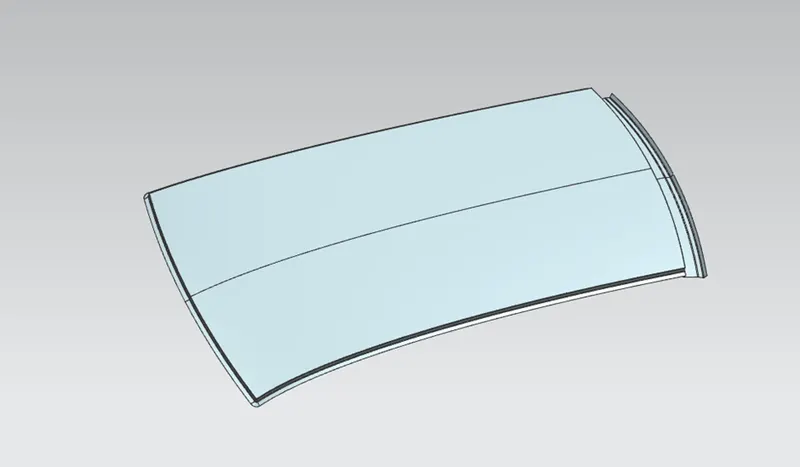
ROOF:
An automobile roof or car top is the portion of an automobile that sits above the passenger compartment, protecting the vehicle occupants
from sun wind, rain and other external elements. Because the earliest automobiles were designed in an era of horse-drawn carriages, early
automobile roots used similar materials and designs.
FRONT ROOF RAIL:
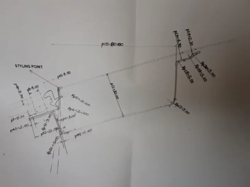
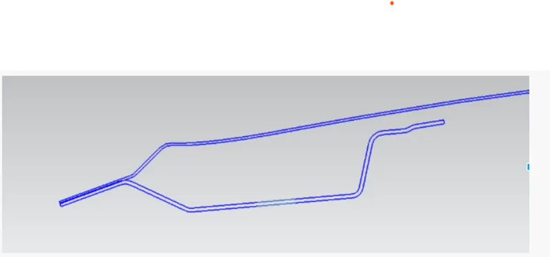
Front roof rails are used in the assembly of a roof in which it provides mounting provisions to windshield glasses and the changes in the front
roof rail influences the frontal visibility of the passenger. The major design factor considered is the headroom clearance. The front roof rail
also provides provision for the mounting the inside rear-view mirror.
Master section of front roof rail.
Front Roof Rail
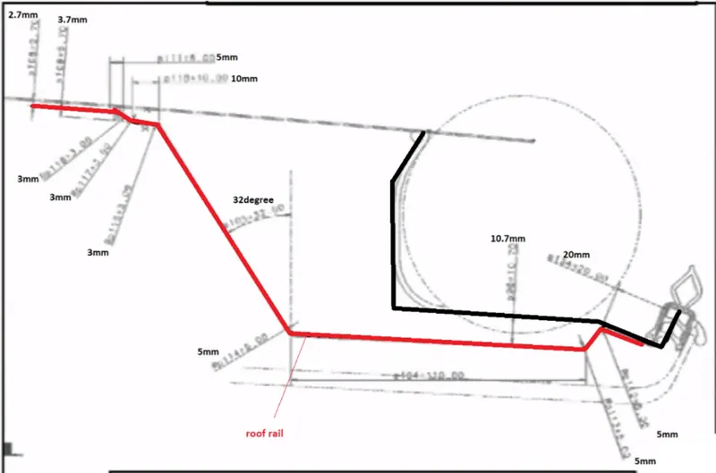
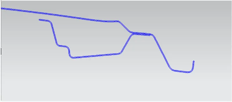
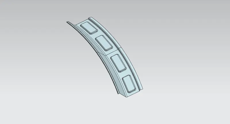
REAR ROOF RAIL
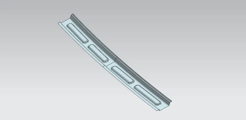
The rear roof rail is the one of the important components of roof assembly which is used for the back door mounting. Similarly to front roof
rail important design consideration includes rear passenger head clearance rear visibility of the vehicle.
Master section of rear roof rail
Rear roof rail
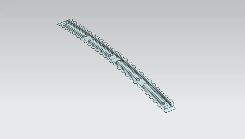
CENTER ROOF RAIL:
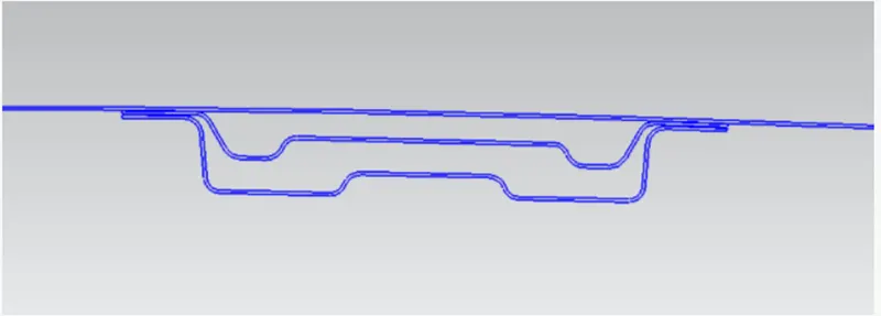
The reinforcement center is used as a cross member between bodyside LH and RH respectively. In some cases, the reinforcement centre is
not joined with the roof in both roof and bodyside. The reinforcement centre and bow roof are joined either spot weld or by mastic sealants
and provision for the same are given.
Master section of reinforcement centre
Centre roof rail
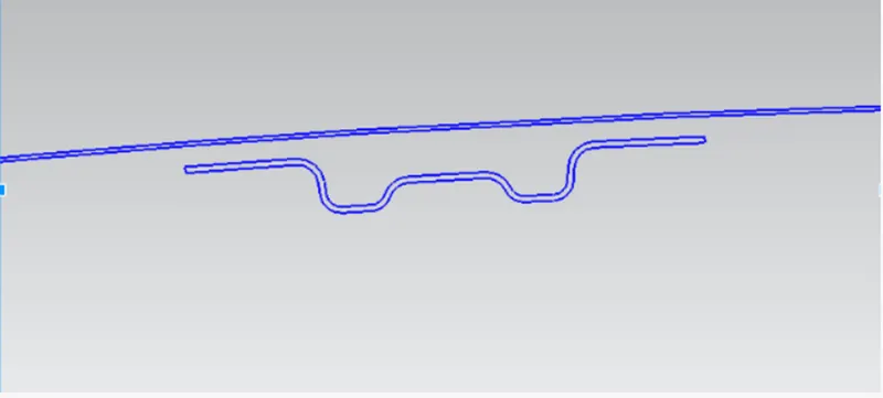
BOW ROOF
It is an additional stiffening member used in the roof assembly for the localized strength improvements and it is joined directly to roof itself
with several spot welding or even with the mastic sealant.
Master section of Bow Roof
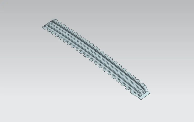
BOW ROOF 1
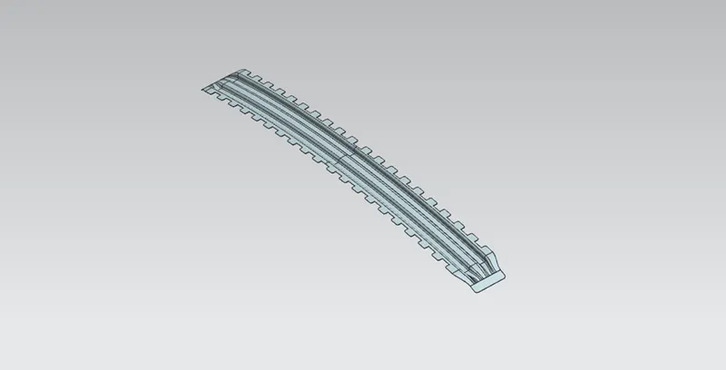
BOW ROOF 2
HEAT DISTORTION CRITERIA:
Heat distortion temperature is the temperature at which the metal softens and deforms under a specific load. This study is done to check
the ability of the roof to withstand high temperature with respect to the positioning of the reinforcements which contribute to increased
strength
Formula to calculate Heat Distortion,
W = [1.73 x 10^(-3) x L] + [1.85 x 10^(-8) (R^2)/t] [ 1.10x10^(-3) x U] - 2.68
Judgement Condition : OK< 2.7> 3.1
Where
L = Roof Length in X-Direction[mm](Roof dimension in O-Y)
R - Roof curvature
R = 2(Rx*Ry)/(Rx+Ry)
Rx = X curvature
Ry - Y curvature
t - Roof plate thickness [mm]
1 - Bow Roof Span [mm]

All are OK conditions. So, the roof has passed the heat distortion criteria.
Snow load Prediction:
This evaluation performed in cold region where snow occurs. Roof design must pass through these calculations to ensure that it has
sufficient stiffness to withstand the load due to accumulation of snow over roof.
Snow load Prediction Formula:
Qr= [ly*t^2]/[ALPHA* s* [(Rx + Ry)/2]^2x 10^-8)
Note: The Qr value given over here is correct. There was a typo error in the formula given in the video.
Where
ALPHA=My*Lx^2 x 10-12, My = Y(Ly-Y)
Judgement condition – Qr>3.1
t=Roof plate thickness [mm]
Ly - Distance between the front and rear roof Rails on the Vehicle along with OY[mm]
Length of Roof panel with the center point between Roof rail Front /Rear as the front and rear reference point
Lx = Distance between the Left and Right end of the roof on the Roof BOW [mm]
Width of the roof panel exposed on the surface.
Y = Distance front Front Roof Rail to Roof BOW[mm]
S = Distance for which Roof BOW bears divided load [mm]
S-L1/2 - 12/2
ly = Geometrical moment of inertia of Roof BOW (Y cross-section )[mm 4]
Rx = Lateral direction curvature radius of roof panel Y cross-section on Roof BOW [mm]
Roof panel curvature Radius of the Length Lx in Front view
Ry - Longitudinal Direction curvature radius of the Roof panel X cross-section on Roof BOW [mm]
Roof panel X curvature radius of length sin Side view.
SNOWED CONDITION

BR2 and RR don’t have divided loads so there is no fourth case.
It describes the snowed condition which the roof should satisfy, if not satisfied then the roofs should should change the dimension till it satisfy the snowed condition.
In the above snowed condition, the third case is not satisfied with the snowed condition. The solution for this is to inform the styling design engineer to change the curvature of the roof or we should change the position of the bow roof.
SECTION MODULOUS:
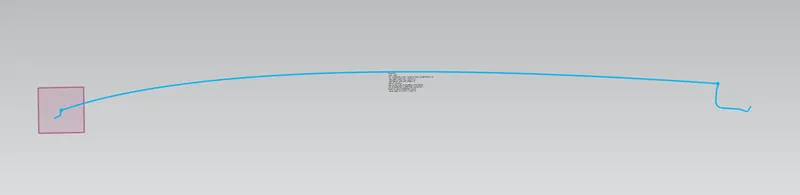
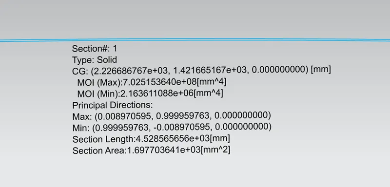
ROOF
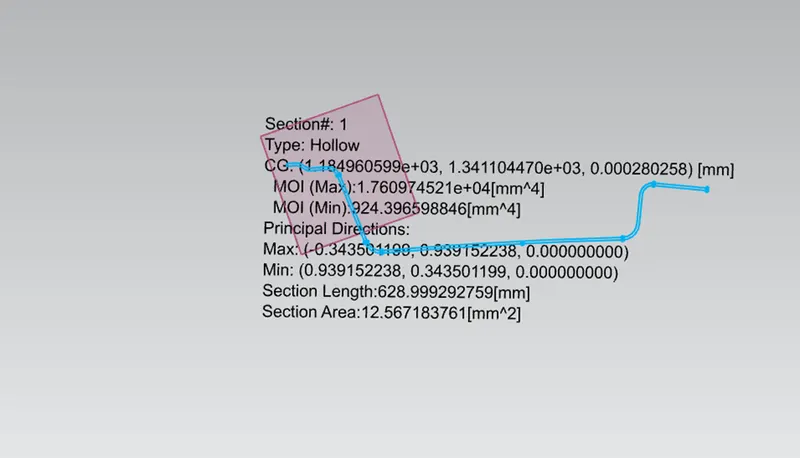
FRONT ROOF RAIL
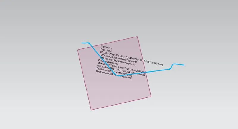
REAR ROOF RAIL
CENTRE ROOF RAIL
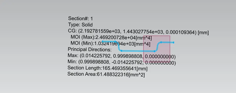
BOW ROOF 1
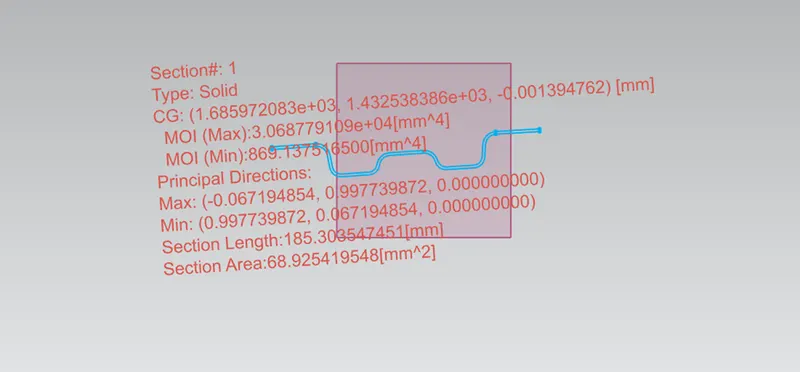
BOW ROOF 2
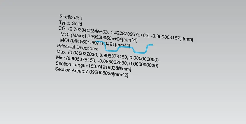
RESULT:
The car roof was designed by considering all the design parameters and the curvature study to resist Heat distortion and snow load condition.