Roof challenge
Introduction:
The part of a car that lies above the passenger compartment and protects the occupants from the sun, wind, rain, and other external elements is known as the roof or car top. The roof is the structure above the wind shield glass that has reinforcements to give overall structure strength.
The roof is a styling surface part which is fixed with the BIW body through the rails and panels inside the upper roof to provide it strength and stiffness.
Types of car roofs:
- Convertible roofs
- Hardtops
- sunroofs
- T-tops.
- Targa tops.
- Vinyl roofs.
these all have uniuq advatages as well as some challanges
Here are the images of different car roofs.
- Convertible roofs:
A convertible or cabriolet (/ˌkæbrioʊˈleɪ/) is a passenger car that can be driven with or without a roof in place. The methods of retracting and storing the roof vary between models. A convertible allows an open-air driving experience, with the ability to provide a roof when required. Potential drawbacks of convertibles are reduced structural rigidity (requiring significant engineering and modification to counteract the effects of removing a car's roof)[1] and cargo space.[2]
The majority of convertible roofs are of a folding construction framework with the actual top made from cloth or other fabric. Other types of convertible roofs include retractable hardtops (often constructed from metal or plastic) and detachable hardtops (where a metal or plastic roof is manually removed and often stored in the trunk).
2.Hardtops:
A hardtop is a rigid form of automobile roof, which for modern cars is typically constructed from metal. A hardtop roof can be either fixed (i.e. not removable), detachable for separate storing or retractable within the vehicle itself.
Pillarless hardtop (often referred to as simply "hardtop") is a body style of cars without a B-pillar, which are often styled to give the appearance of a convertible design.
The pillarless hardtop (often abbreviated to "hardtop") is a hardtop with no B-pillar which is often styled to look like a convertible.[1][2] If window frames are present, they are designed to retract with the glass when lowered. This creates an impression of uninterrupted glass along the side of the car.[3]
A pillarless hardtop is inherently less rigid than a pillared body, requiring extra underbody strength to prevent shake. Production hardtops commonly share the frame or reinforced body structure of the contemporary convertible model, which is already reinforced to compensate for the lack of a fixed roof.
Hardtops tend to be more expensive and collectible than sedan models of the same vehicle.[4]
Some hardtop models took the convertible look even further, including such details as simulating a convertible-top framework in the interior headliner and shaping the roof to resemble a raised canvas top.[citation needed] By the late-1960s such designs could be highlighted with an optional vinyl cover applied on the steel roof.
The hardtop began to disappear along with convertibles in the mid-1970s, partly out of a concern that U.S. federal safety regulations would be difficult for pillarless models to pass. The ascendancy of monocoque construction also made the pillarless design less practical. Some models adopted modified roof styling, placing the B pillars behind tinted side window glass and painting or molding the outer side of each pillar in black to make them less visible, creating a hardtop look without actually omitting the pillar. Some mid- to late-1970s models continued their previous two-door hardtop bodies, but with fixed rear windows or a variety of vinyl roof and opera window treatments.
By the end of the 1990s, almost all hardtop designs disappeared as structural integrity standards continued to increase.
3. sunroofs:
A sunroof is a movable panel that opens to uncover a window in an automobile roof, allowing light and fresh air to enter the passenger compartment. Sunroofs can be manually operated or motor driven, and are available in many shapes, sizes and styles. While the term sunroof is now used generically to describe any glass panel in the roof, the term "moonroof" was historically used to describe stationary glass panes rigidly mounted in the roof panel over the passenger compartment. A moonroof has a glass panel that is transparent and usually tinted. Previous terms include Sunshine Roof, Sliding Head and Sliding Roof.
Overview:
In this project we will be learning how to design the roof in BIW using NX cad.
Majorly we have to study the parts of the roof and study the design considerations used to construct them. There are 4 major parts that we have to construe while making the roof assembly
- Front roof rail
- Bow roof rail
- Reinforcement center
- Rear roof rail
Master section:
these are the predefined values of the each and every commodities which are planned and studied according to the desing considerations
Some of the design considertation that we need to focus duribg the designing teach part is :
- Heat distortion and snow load criteria
- Draft analysis.
- Visibility criteria
- Head clearance
- Curvature study
Designing the front roof rail :
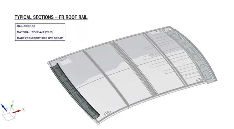
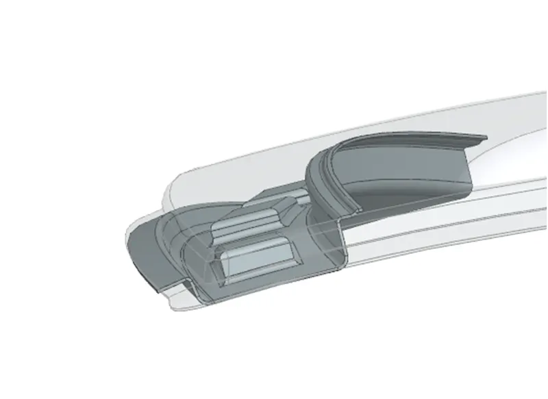
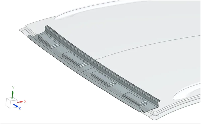
Front roof rail is additional commodities which have been given as reinforcement. it has certain features and commodities which will be supporting bracket or the cabin room
We will be having a styling point which will be a 3 degree
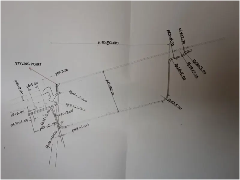
The flange length should be 21.5 mm and all the design dimension given by the design team should be followed very strictly . For the flange part it is 21.5mm because of the wind shield glass and the rubber coatings.
The minimum 80mm is given for the minimum head Clarence for the front driver.
All the demission mentioned in the diagram should be followed as the each and every dimension is according to the design consideration like Visibility criteria/Head clearance/Curvature study
Also keep in mind that we have to keep a thicken to the flange
We will be creating some emboss to give the structure extra strength
Designing the rear roof rail :
Similar to the front roof rail we will be designing the rear roof rail strictly according to the dimension given to us by the design team
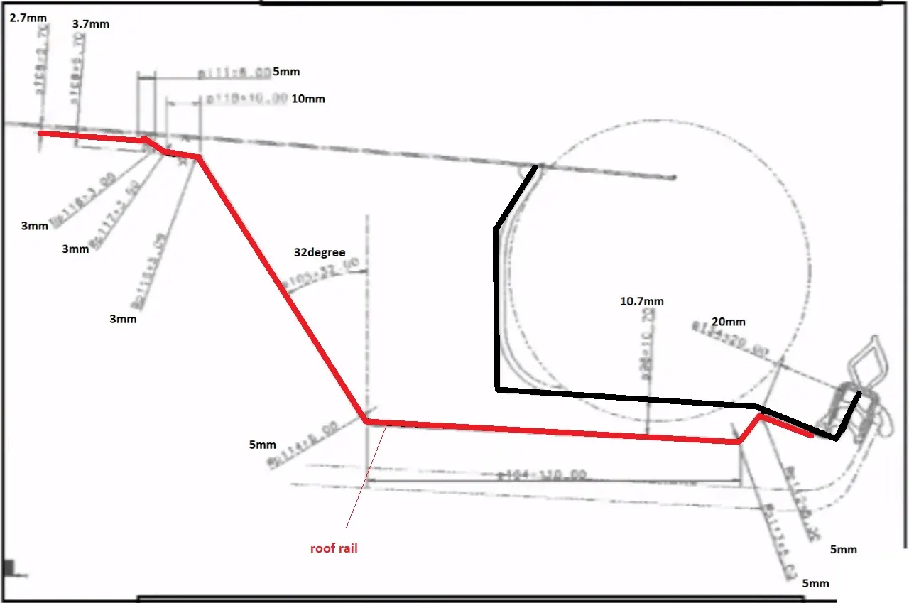
We have to consider the rear visibility creatia . the length of t he flange will also be effected by the rear head room clearance .
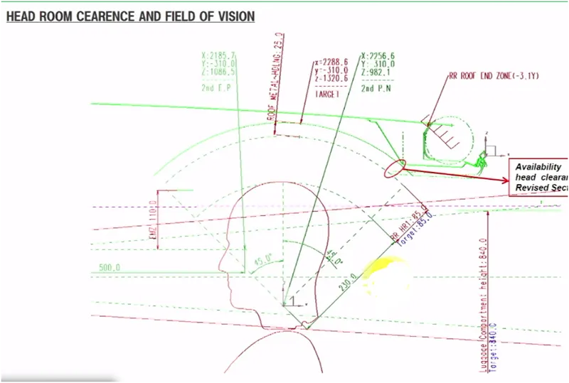
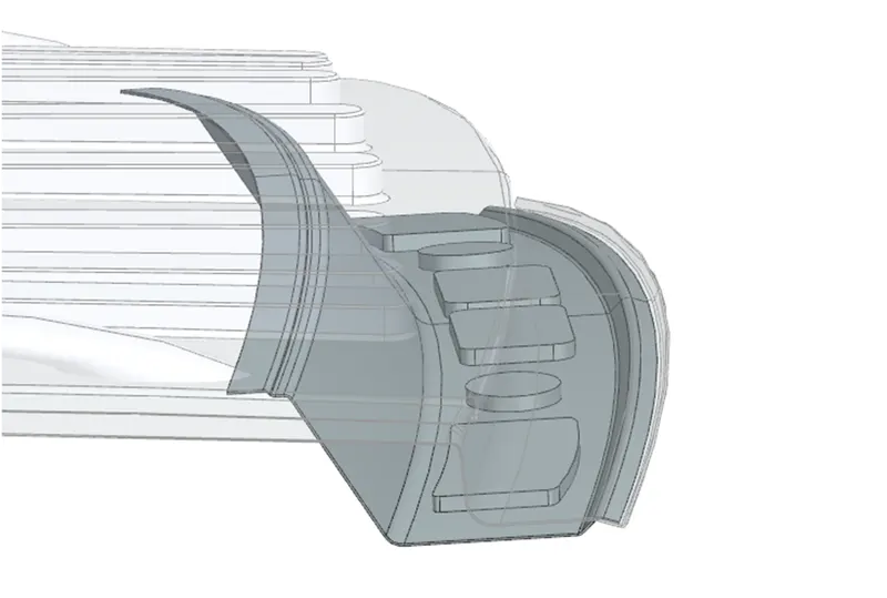
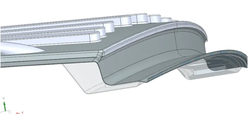
Also the back door mounting is assocated with the back door flange hence it should be created according to that.
Designing the reinforcement roof center :
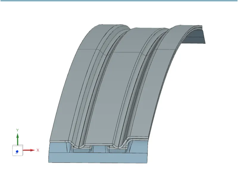
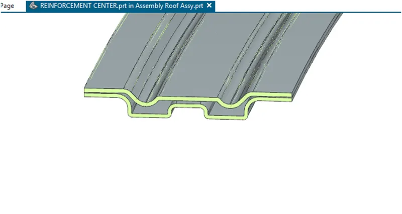
The reinforcement roof center will be one of the important part of the roof. It provide the structural support to the roof and the other components . since the roof curve is good in this case we will be providing a bow roof inside it as well. We have to focus on the part that it does not intersect with each other after the thicken command.
Designing the bows:
the bow will be supporting the roof. it should be desgiend to provide maximum suppport. the postiong of the bow is very important and will effect the heat load as well as the snow load capaticy of the roff. aminimum of 5mm distance should be provided between them also mastic point should also be provided. we can create as many bows we requrie according to the cost and requriment in the roof.
Designing the emboss on the top :
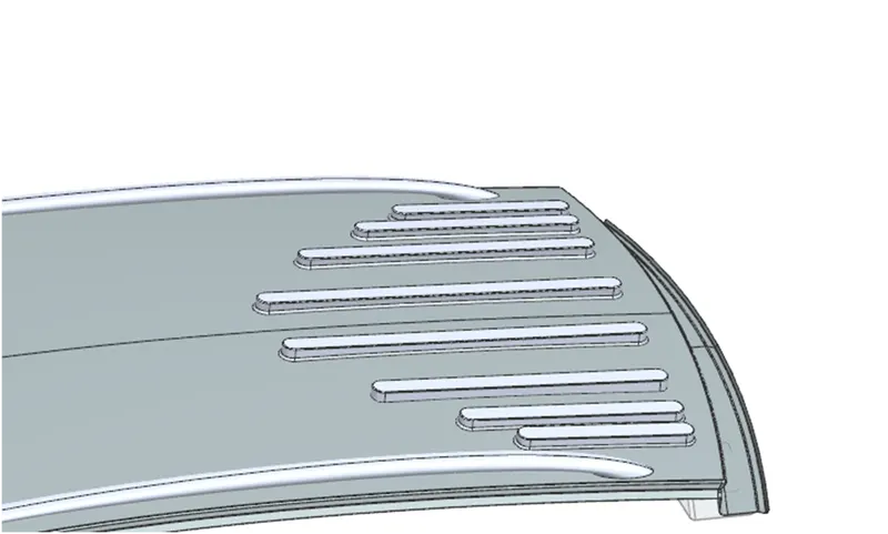
These speacil embosses are given on the top to increase the roof strength . the other application can be that these provide a good aerodynamics to the car .hence improve the downward force on the car giving it more stability.
Draft analysis:
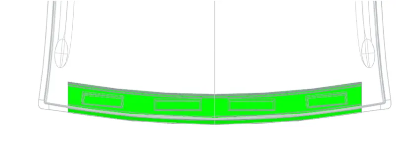
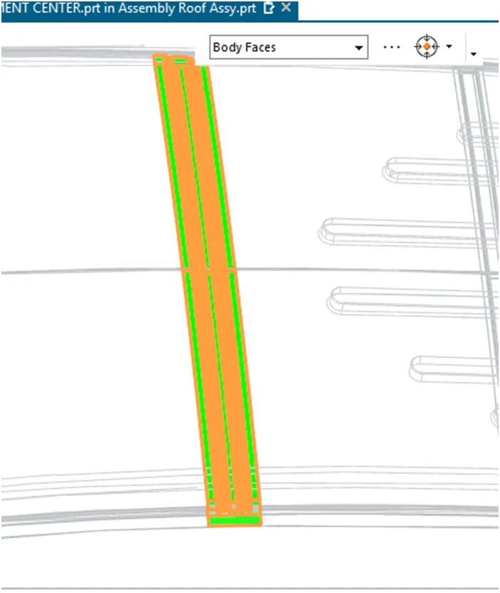
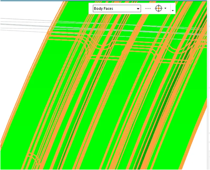
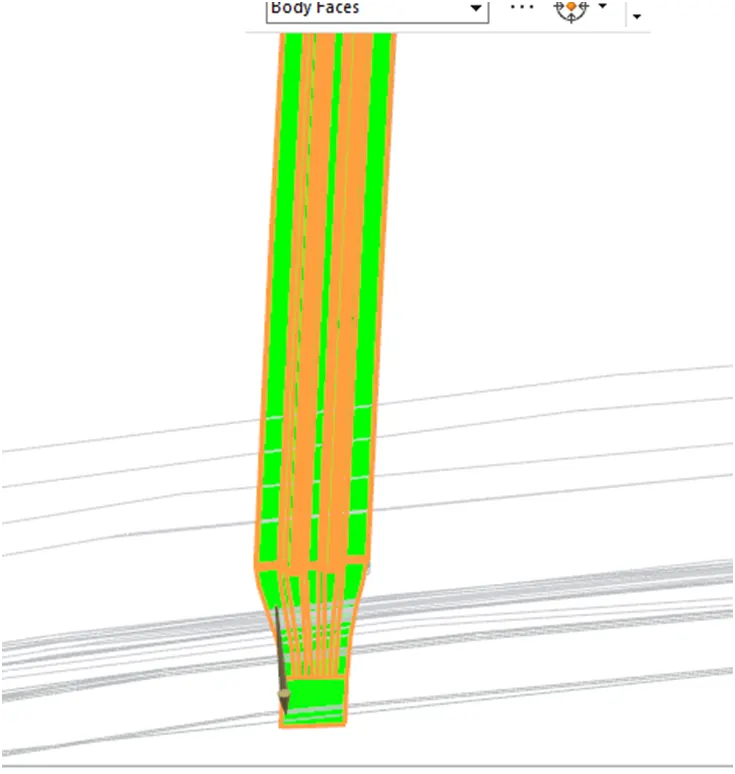
There is a drafts analysis feature in NX that we may use to see if the sheet metal item we created can be deep drawn. This method of analysis is based on colour ranges that define zones on the investigated element where deviations from the draught direction correspond to specified values at each location.
Draft analysis of front roof rail:
Draft analysis of back roof rail:
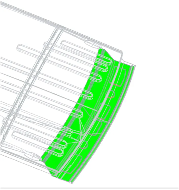
Draft analysis of reinforcement roof center and bow rail:
Positioning of bow roof rails:
The position of all the bow roof depends on major criteria such as
Curvature study of roof
Strength of the roof
Snow load criteria
Heat distortion criteria
Heat distortion :
we have to do some calculation on the current design for the positioning of the bow roof to study weather the quality of roof is good or not .
Bow–roof prediction Formula/ Heat distortion
W = [1.73 x 10^(-3) x L] + [1.85 x 10^(-8) x (R^2)/t] + [ 1.10x10^(-3) x l] - 2.68
Judgement Condition : OK< 2.7> 3.1
Where
L = Roof Length in X-Direction[mm](Roof dimension in 0-Y)
R = Roof curvature
R = 2(Rx*Ry)/(Rx+Ry)
Rx = X curvature
Ry = Y curvature
t = Roof plate thickness [mm]
l = Bow Roof Span [mm]
Procedure:
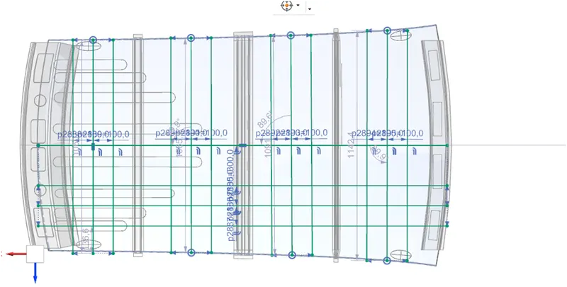
- To calculate the heat distortion we need to to skecth each point and will calculate
- To begin with we will be creating a skecth plane above the actuall roof
- from the center of the we will be measuring the length in x dirrection that will give L
- NOW PLOT A 300 MM IN -3Y
-
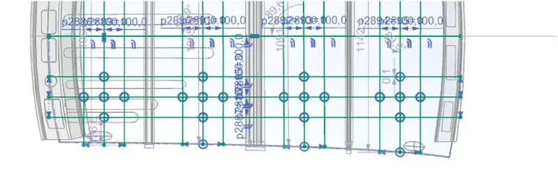
Convert all of the _3Y lines that are 100 mm above and below the _3Y line into refernece lines.
-
In the centre of each reinforcemnt, draw the verical lines and offset them by 100 mm on both sides.
-
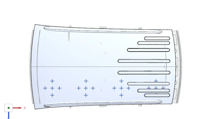
At the place where the lines meet, an intersection point is produced.
-
Draw these lines on the roof's outer panel.
Procedure to measure Rx:
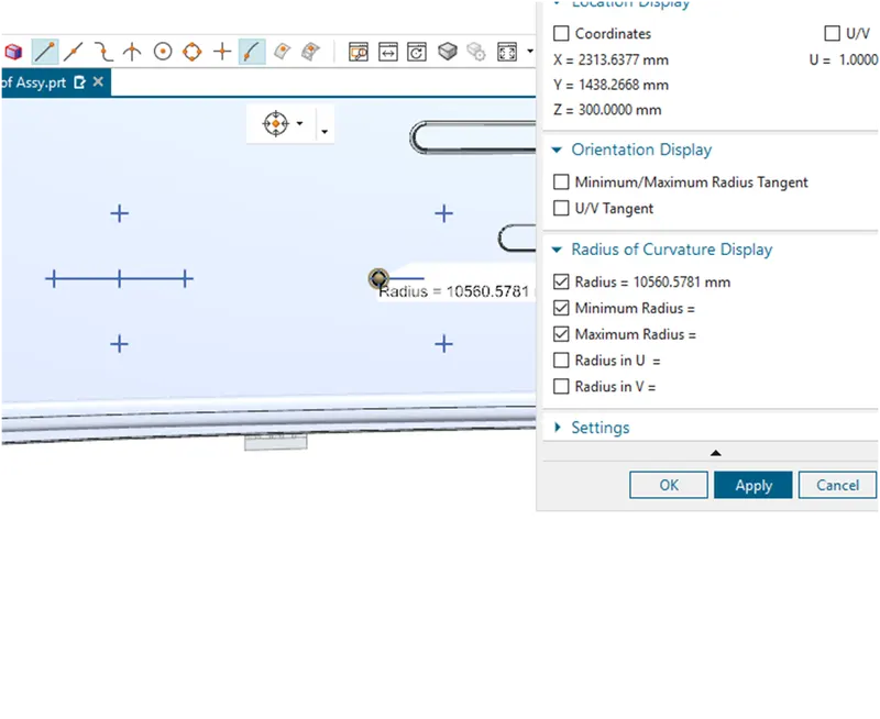
to measure the rx we have to use 3 point arc comand on the rooof and make them , we will be measuring it to get rx
OBSERVATION AND RESULTS:
|
ROOF RAIL SECTION |
L (mm) |
Rx (mm) |
Ry (mm) |
R |
l (mm) |
w |
Results |
|
Front roof rail-Bow roof rail 1 |
2033.7 |
5734.16 |
2613.70 |
3590.710 |
405.91 |
1.609 |
OK |
|
Bow roof 1- reinforcement center/Bow roof 2 |
2033.7 |
4951.01 |
6306.98 |
5547.335 |
394.93 |
2.031 |
OK |
|
reinforcement center/Bow roof 2-Bow roof 3 |
2033.7 |
3982.73 |
10560.57 |
5784.6 |
448.44 |
2.156 |
OK |
|
Bow roof 3- back roof rail |
2033.7 |
3249.48 |
14791.56 |
5328.39 |
262.76 |
1.818 |
OK |
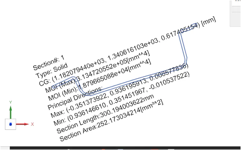
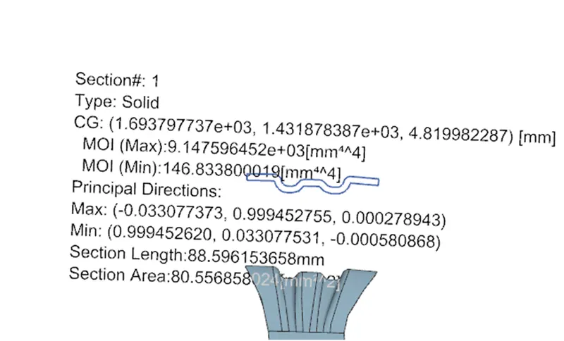
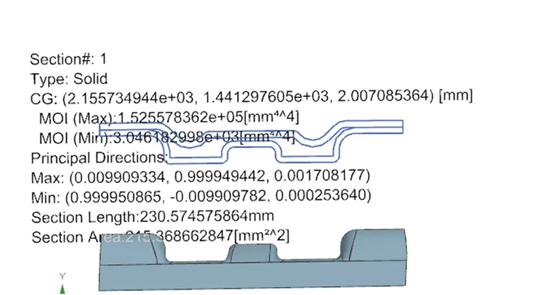
Moment of interia:
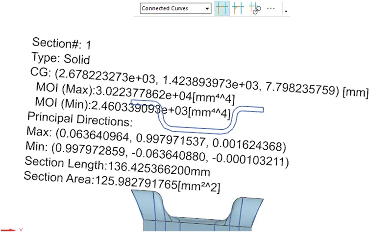
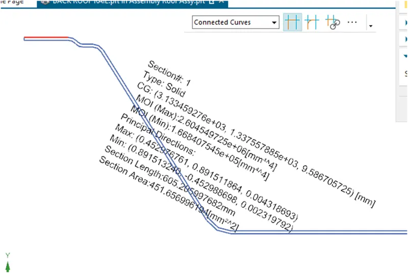
by creating a center plane we can find out the moi of each and every components
FRONT BOW ROOF:
BOW ROOF 1:
REINFORCEMENT CENTER AND BOWROOF2:
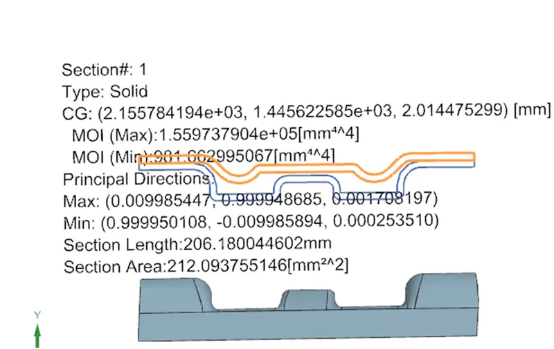
BOW ROOF 3:
BACK ROOF RAIL:
SNOW LOAD:
Qr = [Iy x t2] / [α x s x [(Rx + Ry)/2]2 x 10-8]
Note: The Qr value given over here is correct. There was a typo error in the formula given in the video.
Where
α = My x Lx2 x 10-12 , My = Y(Ly-Y)
Judgement condition = Qr ≥ 3.1
250 ≤ s ≤ 380
t = Roof plate thickness [mm]
Ly = Distance between the front and rear roof Rails on the Vehicle along with 0Y[mm]
Length of Roof panel with the center point between Roof rail Front /Rear as the front and rear reference point.
Lx = Distance between the Left and Right end of the roof on the Roof BOW [mm]
Width of the roof panel exposed on the surface.
Y = Distance front Front Roof Rail to Roof BOW[mm]
s = Distance for which Roof BOW bears divided load [mm]
s = L1/2 + L2/2
Iy = Geometrical moment of inertia of Roof BOW (Y cross-section )[mm4]
Rx = Lateral direction curvature radius of roof panel Y cross-section on Roof BOW [mm]
Roof panel curvature Radius of the Length Lx in Front view
Ry = Longitudinal Direction curvature radius of the Roof panel X cross-section on Roof BOW [mm]
Roof panel X curvature radius of length s in Side view
Procedure:
- To calculate the heat distortion we need to to skecth each point and will calculate
- To begin with we will be creating a skecth plane above the actuall roof
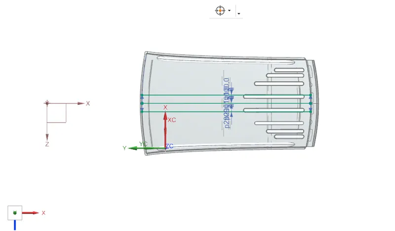
- from the center of the we will be measuring the length in x dirrection that will give L
- NOW from this give a 100mm both side.
-
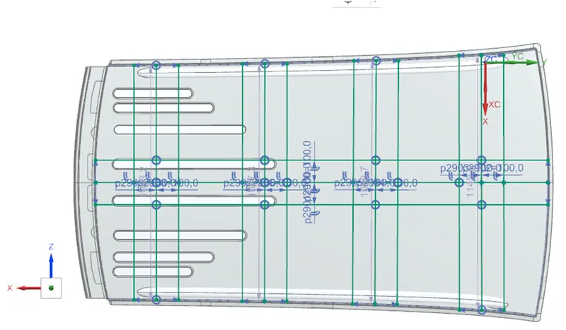
In the centre of each reinforcemnt, draw the verical lines and offset them by 100 mm on both sides.
-
At the place where the lines meet, an intersection point is produced.
-
Draw these lines on the roof's outer panel.
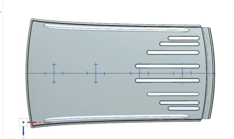
OBSERVATION AND RESULTS:
| Roof section |
|
Lx |
|
|
|
|
|
|
|
|
|
|
RESULTS | |||||||||||
| Front roof to bow roof 1 | 2033 | 1145.79 | 514.06 | 4488.45 | 2644.21 | 514.06 | 461.7 |
146.83 |
780826.296 | 1.025 | 487.88 | 1.29 | NG | |||||||||||
| Bow roof 1 to bow roof 2 | 2033 | 1095.38 | 461.7 | 3772.04 | 6235.48 | 461.7 | 522.5 | 1200.611 | 725469.21 | 0.87 | 491.7 | 6.775 | OK | |||||||||||
| bow roof 2 to bow roof 3 | 2033 | 1068.1 | 522.51 | 4275.67 | 10195.36 | 522.5 | 466.4 | 246.03 | 789674.212 | 0.9 | 494.45 | 0.5 | NG |
According to the observations and results only one condition staistisfed
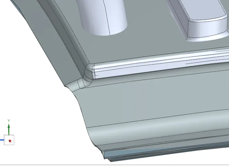
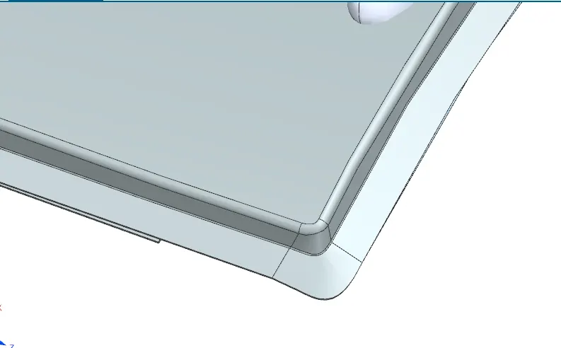
while desgings we have to keep some focus on these special areas:
making conners
screenshots:
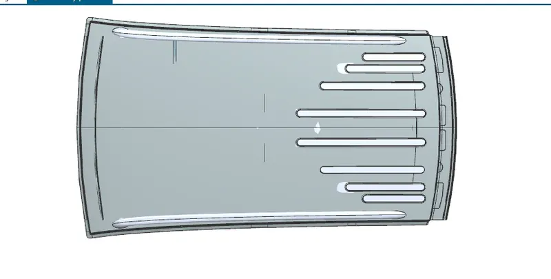
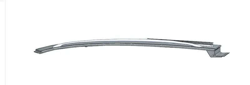
top:
side:
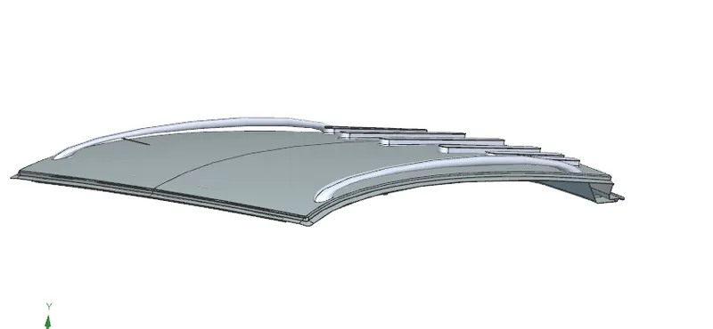
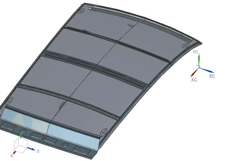
isometric:
Roof Crush Test:
OVERVIEW Roof strength evaluations consist of a quasi-static test conducted on a vehicle’s roof in a manner similar to tests used to judge compliance with Federal Motor Vehicle Safety Standard 216 (Office of the Federal Register, 2009). The main differences between the procedure specified by the Insurance Institute for Highway Safety (IIHS) and that specified by the U.S. federal government are that the IIHS procedure: • Specifies testing one side of a vehicle’s roof, • Does not include a headroom criterion, • Specifies testing to a given displacement instead of a given force level, and • Specifies setting the vehicle’s pitch angle during testing based on the measured on-road pitch angle. An overall rating is assigned based on the peak strength-to-weight ratio (SWR) measured within 127 mm of plate displacement. Supporting documents for the Insurance Institute for Highway Safety (IIHS) roof strength program are available from the Technical Protocols section of the IIHS website
passenger safety is also a very important parameter in front of OEMs. For this reason, strength is a very important criteria for designing a vehicle roof.
IIHS evaluates a vehicle's crashworthiness with the help of six tests: moderate overlap front, driver-side small overlap front, passenger-side small overlap front, side, roof strength and head restraints & seats. For front crash prevention ratings, the Institute conducts low- and moderate-speed track tests of vehicles with automatic braking systems. IIHS also conducts evaluations of headlight systems and of the child seat attachment hardware known as LATCH. The descriptions below explain how each test is conducted and how the results translate into ratings.
Roof strength test
Thousands of people are killed each year in rollovers. The best way to prevent these deaths is to keep vehicles from rolling over in the first place. Electronic stability control is significantly reducing rollovers, especially fatal single-vehicle ones. When vehicles do roll, side curtain airbags help protect the people inside, and belt use is essential. However, for these safety technologies to be most effective, the roof must be able to maintain the occupant survival space when it hits the ground during a rollover. Stronger roofs crush less, reducing the risk that people will be injured by contact with the roof itself. Stronger roofs also can prevent occupants, especially those who aren't using safety belts, from being ejected through windows, windshields or doors that have broken or opened because the roof has deformed.
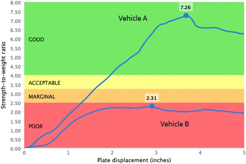
In the test, the strength of the roof is determined by pushing an angled metal plate down on one side of the roof at a slow but constant speed and measuring the force required to crush the roof. The force applied relative to the vehicle's weight is known as the strength-to-weight ratio. The peak strength-to-weight ratio recorded at any time before the roof is crushed 5 inches is the key measurement of roof strength.
A good rating requires a strength-to-weight ratio of at least 4. In other words, the roof must withstand a force of at least 4 times the vehicle's weight before the plate crushes the roof by 5 inches. For an acceptable rating, the minimum required strength-to-weight ratio is 3.25. For a marginal rating, it is 2.5. Anything lower than that is poor.
The figure below shows sample results for two vehicles — one rated good and one rated poor. Peak force for Vehicle A is 7.26. Since that number is higher than 4, the vehicle is rated good. Peak force for Vehicle B is 2.31. Since that number is lower than 2.5, the vehicle is rated poor.
The following video shows how the roof strength test is conducted. In this test of the 2010 Buick LaCrosse, the peak force is 19,571 pounds for a strength-to-weight ratio of 4.90 and a good rating. The playback speed of this video has been increased. The plate normally crushes at a rate of about 1/8 inch per second.
The strength of the roof structure to occupant the protection in real world crashes, requiring the maximum moving distance of the roof structure should be less than 127mm when the induced load is 1.5 times the vehicle weight.
For the test, the passenger car shall be rigidly placed or positioned on horizontal surface with the doors locked and the window closed.
In every test, the roof is crushed 5 inches. What varies — and can't be seen in a video — is the force used by the machine to achieve that degree of crush. To demonstrate how roof strength can vary and what those differences mean for people inside a vehicle during a rollover, IIHS conducted a demonstration in which two vehicles with different roof strength ratings were subjected to identical force. This video shows what happened when the 2009 Volkswagen Tiguan, rated good for roof strength, and the 2008 Kia Sportage, rated poor, were each subjected to a crush force of 15,000 pounds.
This test can be conducted on either side of the roof structure, the front left or front right side but not on both sides in one single test and still meet the requirements of the test. The rigid plate shall not move faster than 0.5 inches/second and the force applied on the plate shall not exceed the lesser of 1.5 times the unloaded vehicle weight (UVW) expressed in kilograms multiplied by 9.8 or 5000lbs
Also, the direction of the forces shall be downward and perpendicular to the lower surface of the rigid plate and such that moves in a straight line without rotation. The duration of the test shall not exceed 120 seconds. The longitudinal axis of the plate is pitched forward at a 5° angle as viewed from the side of the passenger car.
Rollover accidents of a car are the most occurring accidents that we see in our daily lives. The passengers experience major injuries like neck, head and spine injuries. So, to reduce the injuries of a passenger from major fatalities it is important to provide safety in the car. Though safety is provided by seat belts and airbags during accidents, the passenger must have sufficient space for survival in the car during accidents. The roof of the car must have high strength to resist the crush force to avail the passenger some space for survival. Therefore, in this project, we have carried out roof crush test using Federal Motor Vehicle Safety Standards (FMVSS216) standards in LS dyna software. We have used Hyper mesh software to mesh the model and to apply boundary conditions to it. And the rigid plate is used to crush the car roof as specified by FMVSS216 standards. The rigid plate is oriented on the car roof as specified by Insurance institute of highway safety (IIHS). And an alternate material is used to the car roof structure to the baseline model to check the crashworthiness of new material. The outcome of test results of the new material's strength to weight ratio (SWR) was compared to baseline model and the new material is proposed for the roof (B-pillar) which is found to be more crashworthy.
TESTING Roof
Engineering testing is different from scientific testing. Product or component testing is done to establish performance, not to discover or validate new scientific theories. Engineering testing does not require invariant test conditions or reproducible results. If the results are adequate in terms of system performance, it makes no difference what variations of input parameters or test results develop, as long as the inputs are representative and include the "worst case" and the results, even if the "worst case" is acceptable. Since the "worst case" may be hard to identify, guaranteeing performance may require a number of tests in which the input parameters are varied along the full range of probable values.
Reproducibility is a matter of convenience and economy for the testers; it has no fundamental engineering significance. Reproducible results with tests that result in catastrophic failures are an unreasonable and unnecessary goal. Vehicle makers could do hundreds of rollover tests on each new platform, (basic vehicle family) covering the full range of parameters of concern, just as they are currently doing for other certification testing. The idea that roof strength must be evaluated with only one test or even one type of test is an unnecessary concession. Thus, the new Jordan and CRIS rollover test protocols, while they may be of great illustrative or forensic value, do not represent a necessary or even necessarily a desirable approach to greenhouse testing, and their advancement may represent an unnecessary compromise with respect to vehicle producers' true obligations.
STRUCTURAL FAILURE
Let us consider the possibility of developing a formal definition for structural adequacy for something like a vehicle greenhouse under conditions like those encountered in rollover accidents. Let us define a structure, most generally, as a set of mechanically connected components which is capable of transmitting significant loads to components remote from the point(s) of loading. A component is an identifiable piece of the structure, e.g., a beam element, or a joint.
Now, what we need in a vehicle greenhouse is something like what is commonly thought of as rigidity. But what is rigidity, and how is it to be defined for evaluative or regulatory purposes? Consideration of the mechanisms of structural failure might suggest a definition which includes a concept like this: A rigid structure is one that does not exhibit plastic hinges when loaded (to some significant level). A plastic hinge results when a component or an area or element in a component is subjected to a bending moment (force acting through a distance) beyond its elastic limit causing it to exhibit plastic failure. Note that a "rigid structure," so defined, can still fail in other ways, essentially with pure compressive or tensile loads, although many failures with these loading modes may still involve localized plastic hinges, e.g. slender column buckling.
Plastic hinges are designed in elements of certain structures, notably buildings expected to be subject to seismic loads. The hinge elements at the base can absorb energy and prevent the complete collapse of the structure by "giving" a little as the structure is loaded. Plastic hinges are largely unknown, however, in mechanical engineering design. The problem is that they occur with roof collapse in rollover accidents.
(A caveat: Strength is a property of materials, not of structures. A given material, say a specific, well-defined steel alloy, will have various strengths as determined by various types of tests -tensile, shear- and will yield consistent strength values under well-controlled testing conditions. Structures, on the other hand, have no simple "strength"; rather they have the ability to resist a specific load with a given method of application of that load. The "method" includes the point at which the load is applied, the direction of loading, and duration and the rate of the loading process. Change any of these, and the "strength" of the structure may change.)
strength evaluations are conducted on a quasi-static test system manufactured by MGA Research Corporation (Figure 3). The system consists of an upright assembly and an attached loading head that can be fixed at varying heights from the ground as well as at pitch angles ranging from −5 to +5 degrees to accommodate testing on the driver or passenger side. The roll angle is permanently fixed at 25 degrees. Four hydraulic actuators control the movement of the platen along two linear guides. The entire system is mounted on a T-slot bed plate anchored to the floor of the test facility. Figure 3 MGA Roof Crush Test System Two HR A-36 — W10x88 I-beams are mounted on the bed plate perpendicular to the longitudinal axis of the platen. The vehicle, with attached rocker panel support system, is placed on these beams. The vehicle is adjusted so that:
- The longitudinal centerline of platen is within 10 mm of the initial roof contact point.
- The yaw angle of the vehicle relative to the longitudinal axis of the platen is 0 ± 0.5 degrees. 3. The midpoint of the platen’s forward edge is 254 ± 10 mm forward of the most forward point of the roof (including windshield trim if it overlaps the roof) lying on the vehicle’s longitudinal centerline.
- The pitch angle of the vehicle matches the on-road angle, while also accounting for any difference between the platen’s pitch angle and the nominal −5 degrees. The maximum combined difference of the vehicle and platen pitch angles from their targets is ± 0.5 degrees. (For example, if the onroad vehicle pitch angle is −0.2 degrees and the platen pitch angle is −5.2 degrees, the target sill angle for the test is −0.4 ± 0.5 degrees.) If necessary to achieve this angle, shims are inserted between the rocker panel supports and the W10x88 I-beams attached to the bed plate. 2021 Insurance Institute for Highway Safety Roof Strength Test Protocol (Version IV) 988 Dairy Rd, Ruckersville, VA 22968. All rights reserved. May 2021 — 4 Once the vehicle is positioned correctly, the rocker panel supports are clamped to the two perpendicular Ibeams, and the beams are marked to allow confirmation that the vehicle position is maintained during the test. For body-on-frame vehicles, the frame is supported to prevent the weight of the chassis from stressing the body at the body mounts. The roof is crushed to a minimum displacement of 127 mm at a nominal rate of 5 mm/second. Some tests are conducted to a greater displacement to collect additional strength data for research purposes. Force data are recorded from five load cells (Interface Inc., model 1220) attached to the loading platen. Displacement data are recorded from four linear variable displacement transducers (LVDTs) (MTS Temposonics model GH) integrated into the hydraulic actuators. Figure 4 shows the locations of the load cells and LVDTs on the loading platen. Force and displacement data are collected with a National Instruments USB-6210 data acquisition system and reported at 100 Hz. These data are based on a sampling rate of 2,000 Hz, with every 20 points being averaged to produce the output data at 100 Hz. The displacement-time histories from the LVDTs are compared to verify that the platen’s roll angle and pitch angle (relative to the vehicle’s on-road pitch) were maintained at 25 ± 0.5 degrees and −5 ± 0.5 degrees, respectively. The precrash and postcrash conditions of each test vehicle are documented with still photographs. The position of the vehicle in the test fixture also is recorded. Motion picture photography is made of the test with real-time video cameras. 72 in. 6 in. 6.5 in. 30 in. 3.5 in. Load cell LVDT Figure 4 Position of Load Cells and LVDTs on Loading Platen 2021 Insurance Institute for Highway Safety Roof Strength Test Protocol (Version IV) 988 Dairy Rd, Ruckersville, VA 22968. All rights reserved. May 2021 — 5 CALCULATING THE STRENGTH-TO-WEIGHT RATIO (SWR) RATING Force and displacement data are recorded for 5 seconds prior to each test, while the test system holds the loading platen at initial roof contact. The data recorded from 1 to 4 seconds of this hold time are averaged for each channel to produce a measurement offset that is subtracted from the data recorded during the crushing of the roof. After removing the offset for each channel, the force-displacement curve is plotted using the summed output from the five load cells and the average displacement from the four LVDTs. The maximum force prior to 127 mm of platen displacement is divided by the measured curb weight to obtain the SWR. Both the force and curb weight are rounded to the nearest pound prior to performing the calculation, and the resulting SWR is rounded to the nearest one-hundredth of a unit. Displacement is rounded to the nearest 0.1 mm. (The maximum displacement where the load can be used for the vehicle rating is 126.9 mm.) The vehicle’s rating is assigned based on the boundaries listed in Table 1. Table 1 Roof Strength Rating Boundaries SWR Rating ≥ 4.00 Good ≥ 3.25 to < 4.00 Acceptable ≥ 2.50 to < 3.25 Marginal
All trim levels sharing the tested vehicle’s body type and roof structure are assigned the same rating as the typically equipped trim level, provided their curb weights do not exceed 110% of the selected vehicle’s weight. Based on published curb weights from multiple sources, any trim levels that may exceed this weight are identified and weighed. If the weight does exceed 110% of the weight of the selected vehicle, a unique SWR is calculated for that trim level. If this SWR results in a lower rating, both ratings are reported for the model, with a split according to trim level. If a trim level weighs more than 110% of the typically equipped model, but the lower SWR does not fall in a lower rating band, only the original SWR and rating are reported for the model.
RESULTS
the designing and calcualtion of the roof with all its parts were completed according to the industrual regualtion to produce a good quality roof