Roof challenge
ROOF DESIGN
AIM :
To design the complete roof from styling to a completed Roof with Bow roofs, Front and Rear Panel, Centre reinforcement for Roof strength then perform Draft Analysis, Inertia analysis, Load Calculations.
Car Roof :
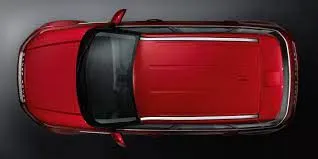
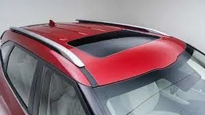
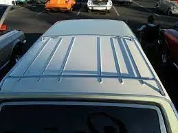
An automobile roof or car top is the portion of an automobile that sits above the passenger compartment, protecting the vehicle occupants from sun, wind, rain, and other external elements.
Roof rails BIW:
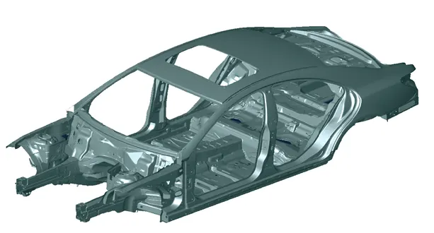
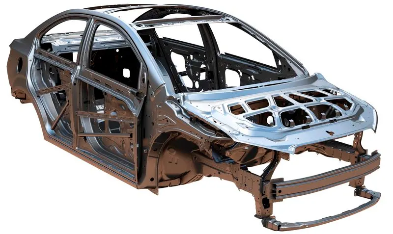
Car Styling( Class A) :
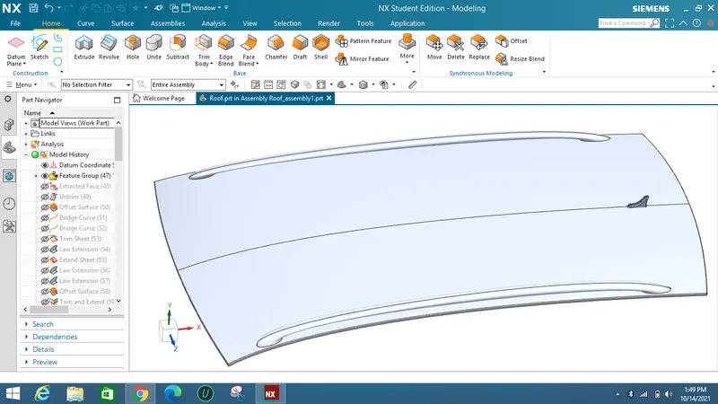
As a raw data a car roof is given as a styling from a Class A team as shown below.
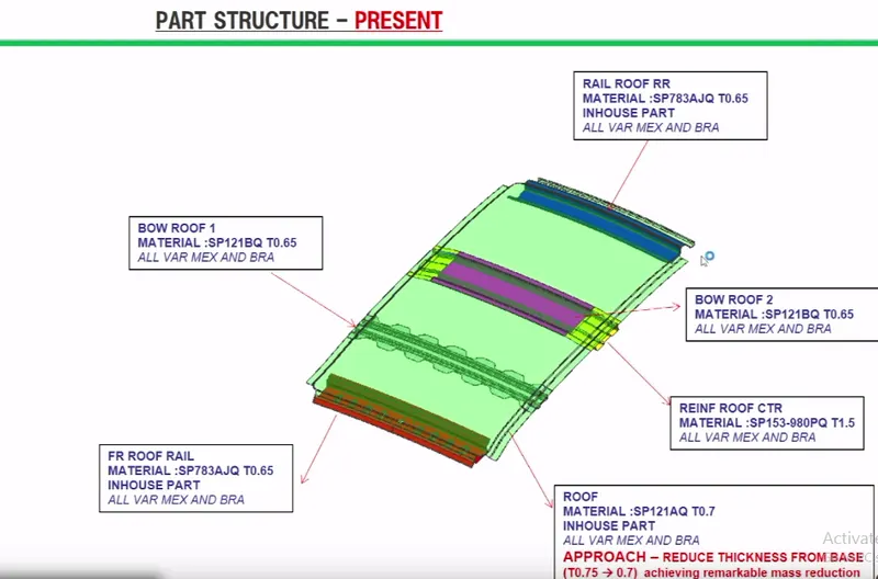
There are typical sections like Front, Rear panel, Bow roofs and centre reinforcement for Roof strength.
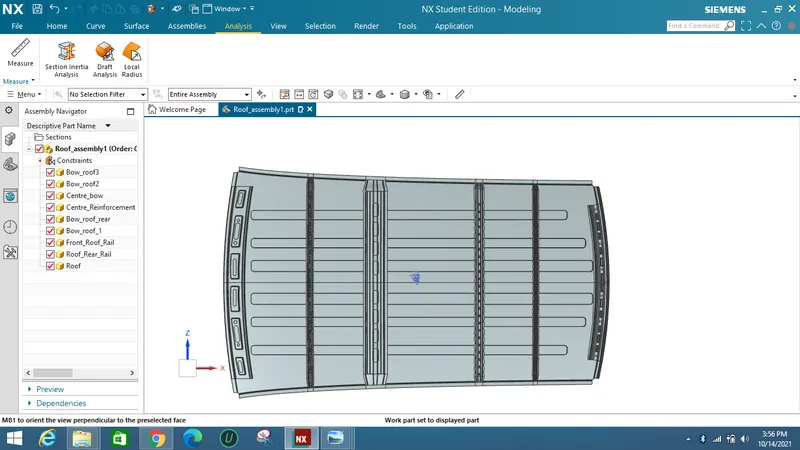
The basic overview and part sections of a roof will looks like below image 1 :
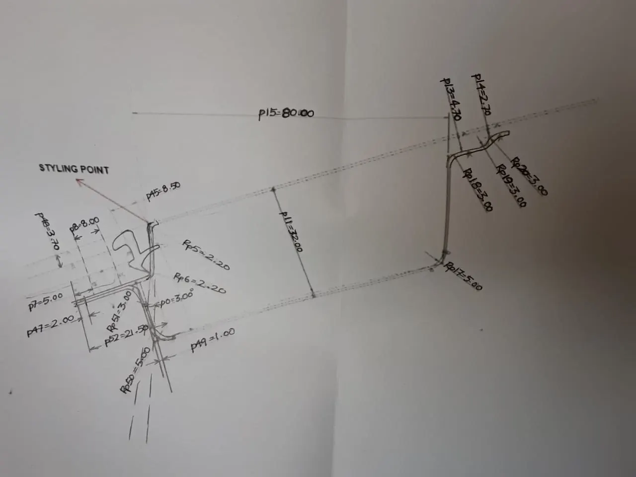
The assumption of the Bow and centre bow sketches are given below :
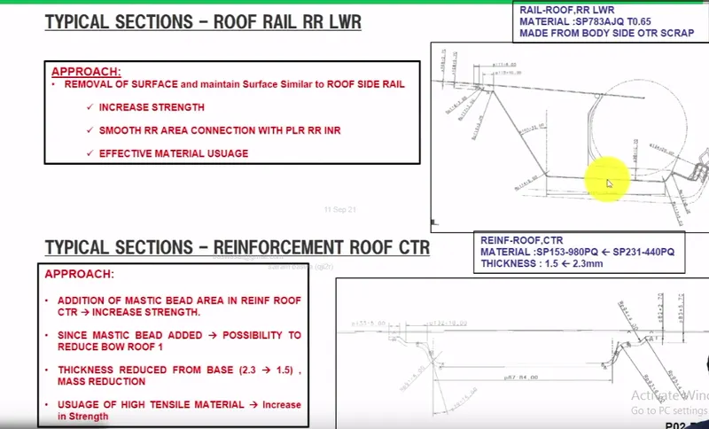
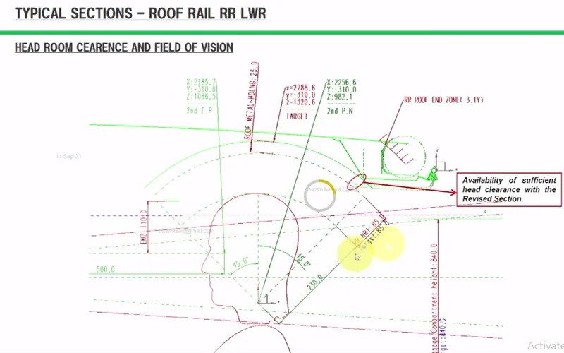
The front roof rail and the bow roof 1 is designed in a manner that does'nt leave a obstruction to the vision of a driver.
Roof Flange Design :
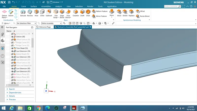
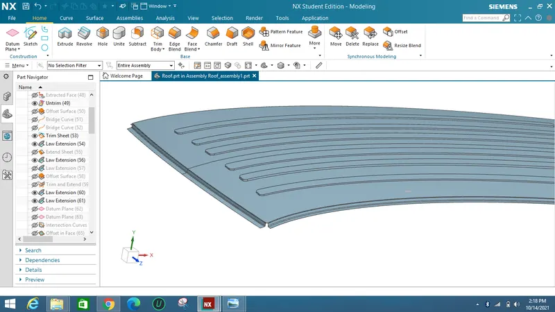
As per the criteria of Front roof rail and head of a average passenger the flanges were created using law extension command.
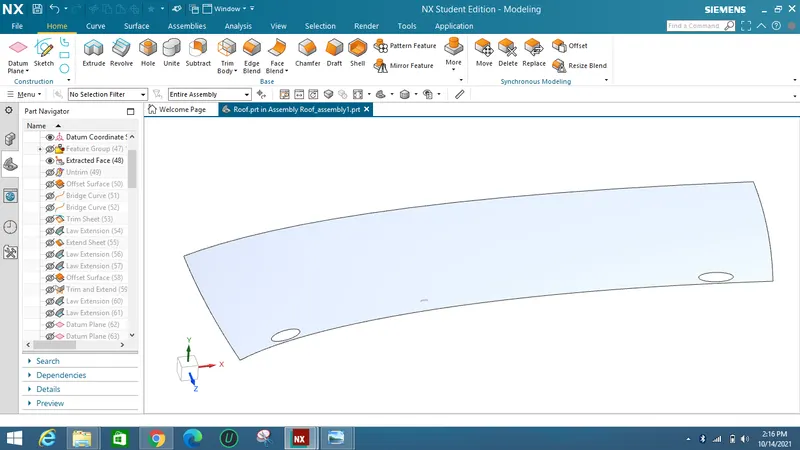
First the face should be extracted, take an half of the roof then make a flange there after it is mirrored and thickened.
By referring to the input sketch parametres Roof flange and front rail is designed.
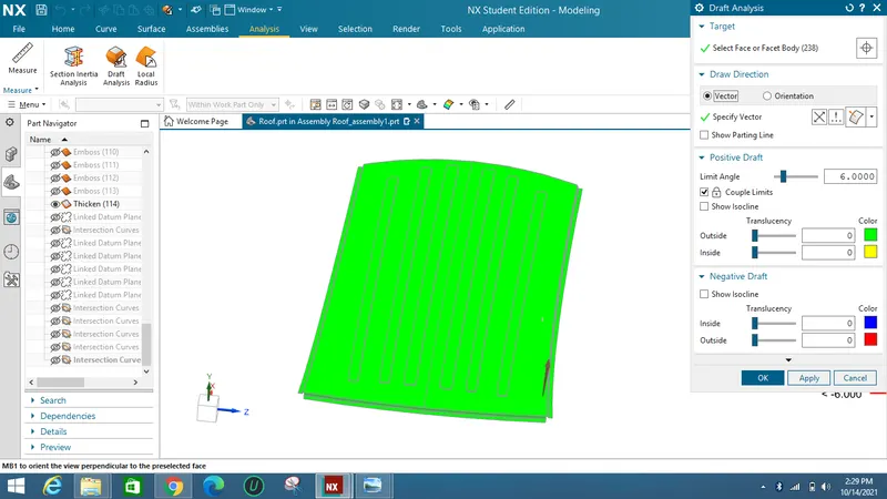
Draft Analysis :
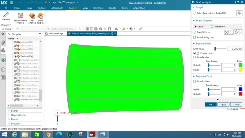
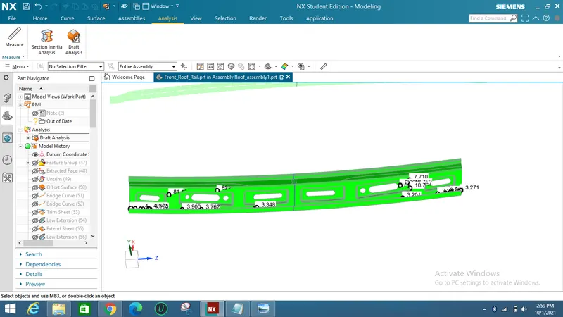
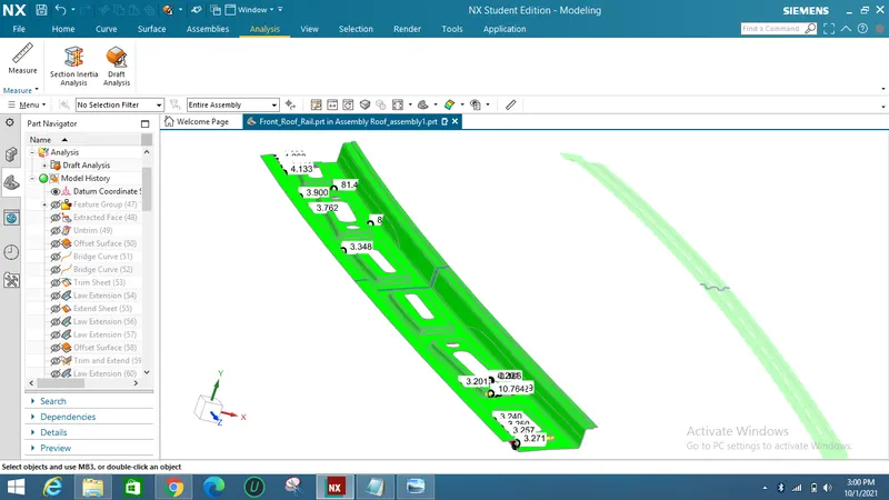
As per the standards the angle maintained for obtaining a exact punch a 3 degree minimum is maintained.
Front Roof rail Design :
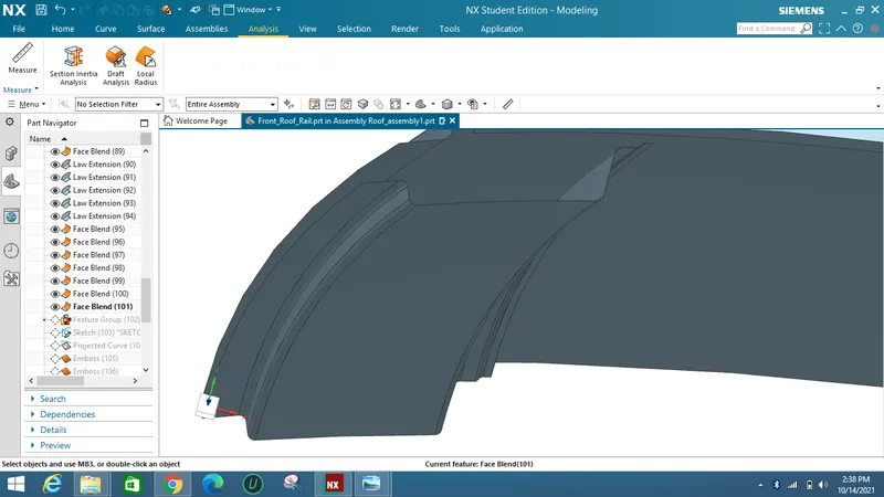
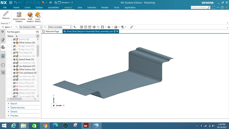
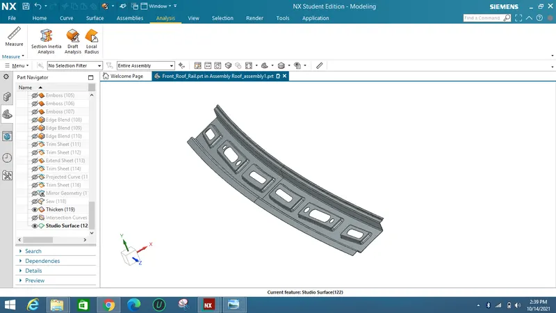
As referring to the Front rail sketch Front roof rail is designed.
By making offsets and law extensions Roof rail is designed with maintaining of 7 degree draft.
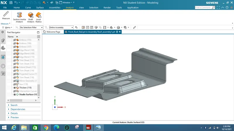
Embosses were added for strengthening the part.
Draft Analysis :
As from the standard sheetmetal criteria a minimum 3 degree of draft angle should be provided on the sheet metal.
Section Inertia Analysis :
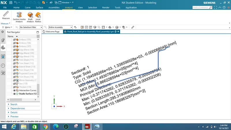
As from the below image the min Inertia value obtained is I = 5866 mm^4 where the load starts effectively.
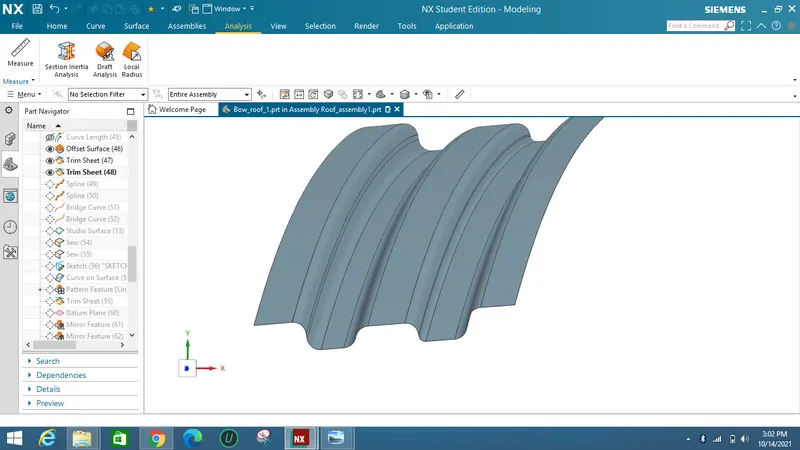
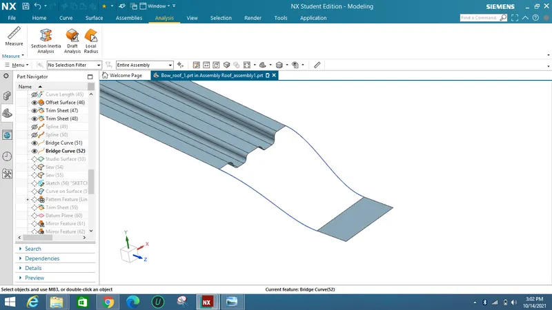
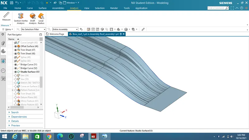
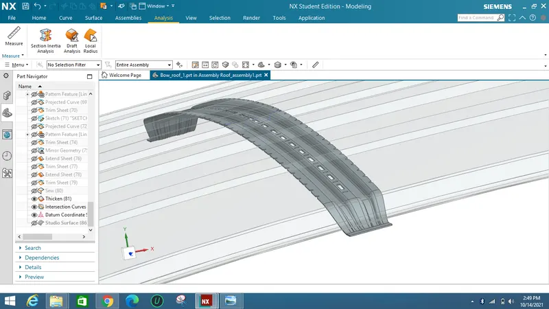
Bow Roof 1:
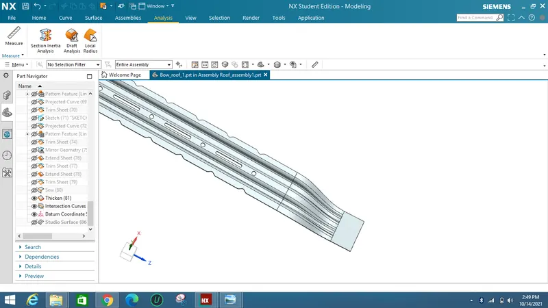
Below is the reference master section given for designing a bow roof :
The above is a roof and the below master section referred as a Bow roof for strengthening roof.
Draft Analysis :
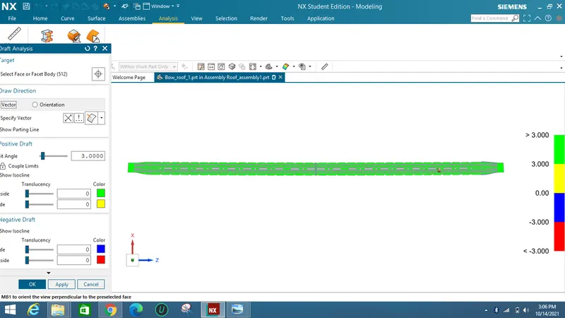
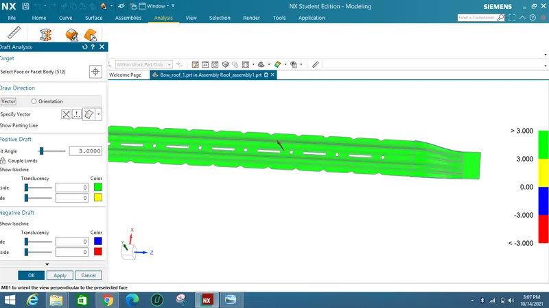
As from the standard sheetmetal criteria a minimum 3 degree of draft angle should be provided on the sheet metal.
Section Inertia Analysis :
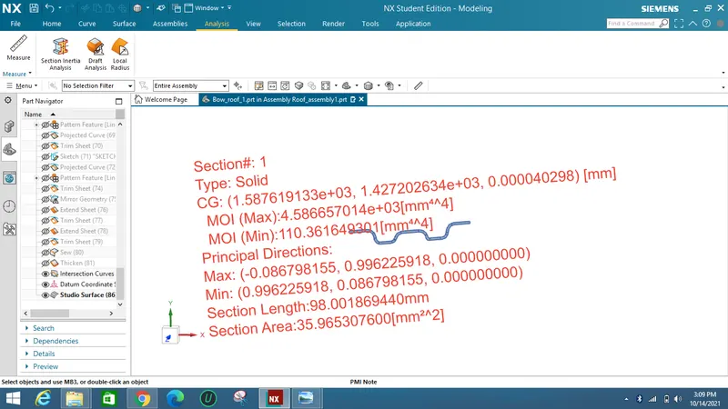
As from the below image the min Inertia value obtained is I = 110 mm^4 where the load starts effectively.
CentreRoof Reinforcement :
Below is the reference master section given for designing a Centre roof reinforcement :
The above is a roof and the below master section referred as a Bow roof for strengthening roof.
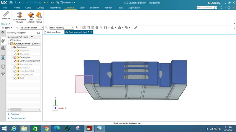
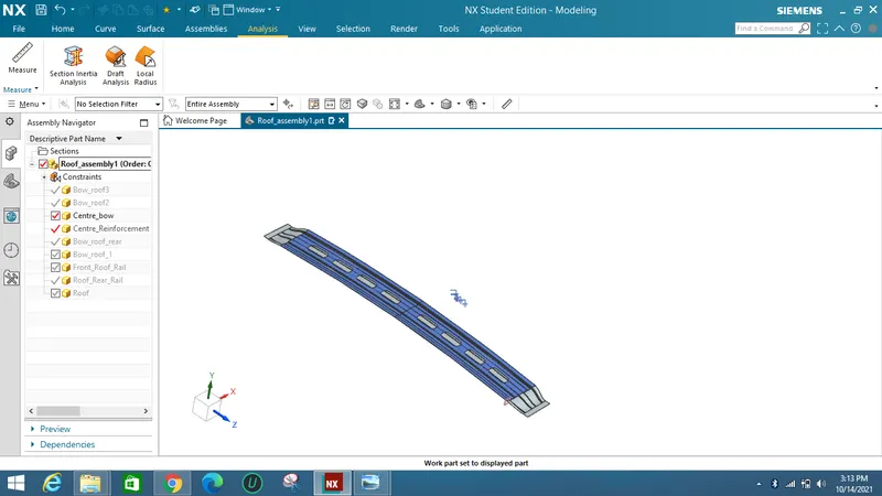
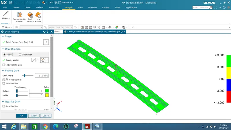
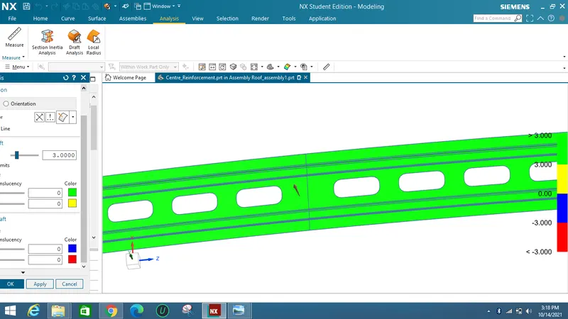
Draft Analysis :
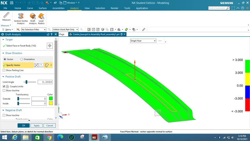
Centre Bow :
As from the standard sheetmetal criteria a minimum 3 degree of draft angle should be provided on the sheet metal.
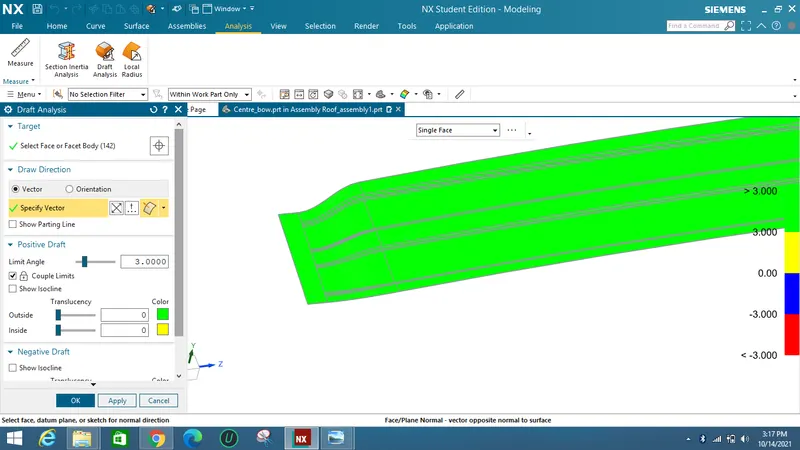
Centre Reinforcement :
As from the standard sheetmetal criteria a minimum 3 degree of draft angle should be provided on the sheet metal.
Section Inertia Analysis :
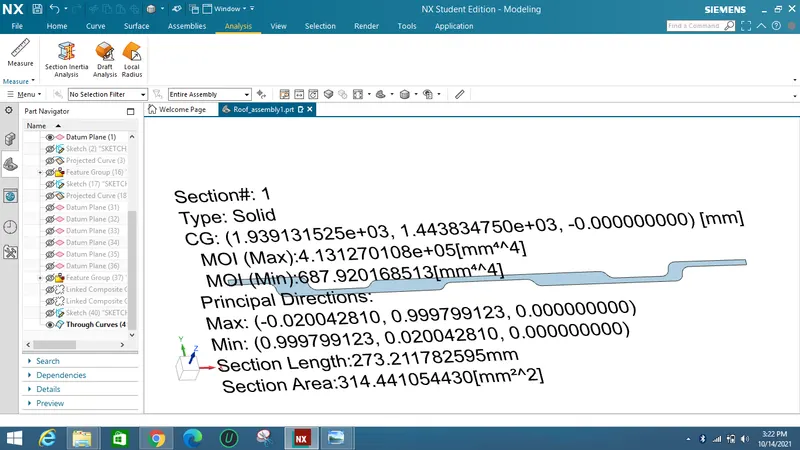
The Section Inertia Analysis for total Bow and Reinforcement is :
The value at which the load acts effectively is I = 687 mm^4
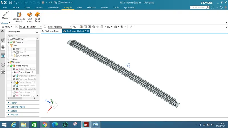
Bow Roof 2 :
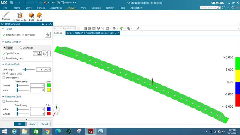
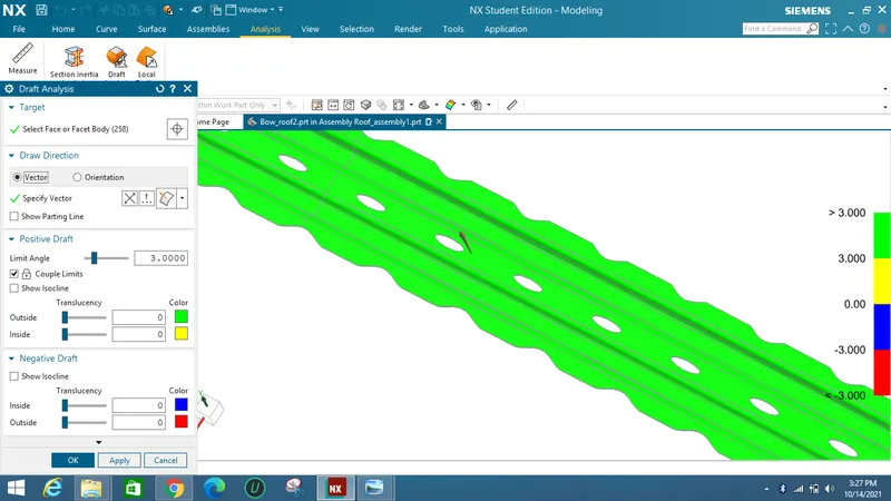
Draft Analysis :
The minimum draft angle required is 3 degree for sheet metal.
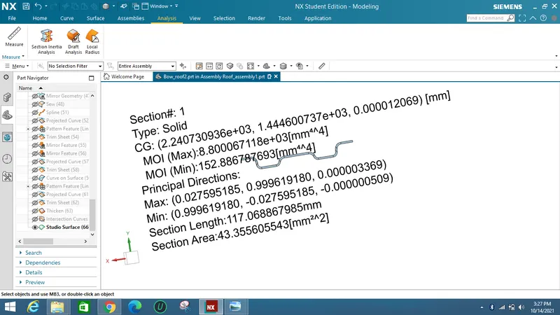
Section Inertia Analysis :
The value at which the load acts effectively is I = 152 mm^4.
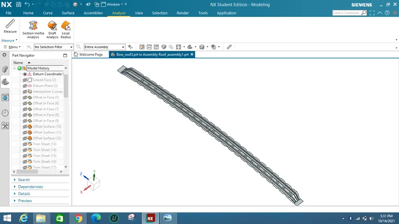
Bow Roof 3 :
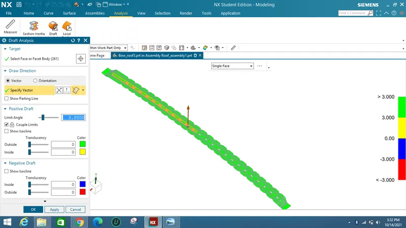
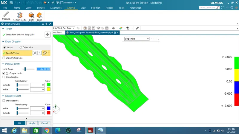
Draft Analysis :
The minimum draft angle required is 3 degree for sheet metal.
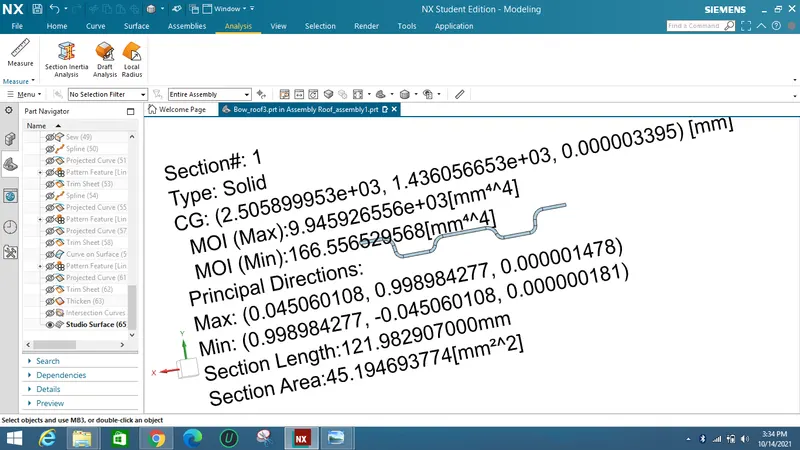
Section Inertia Analysis :
The value at which the load acts effectively is I = 166 mm^4.
Bow Roof 4 :
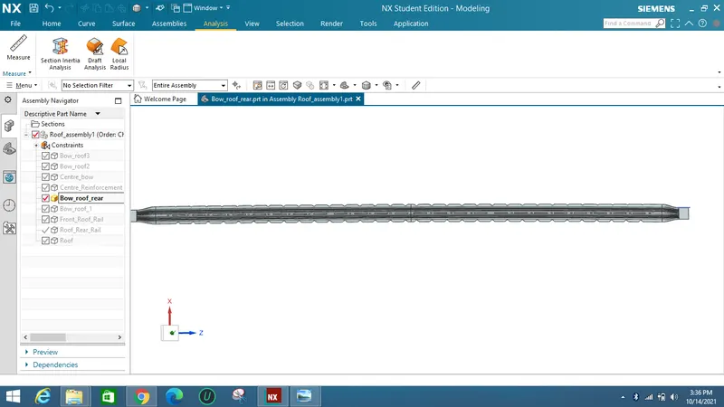
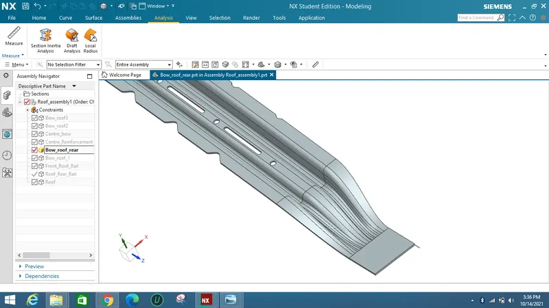
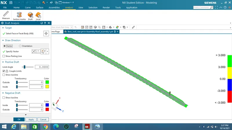
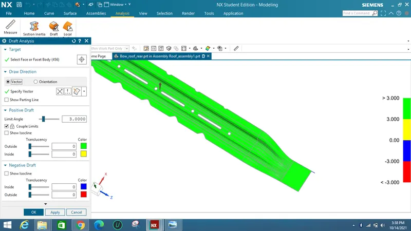
Draft Analysis :
The minimum draft angle required is 3 degree for sheet metal.
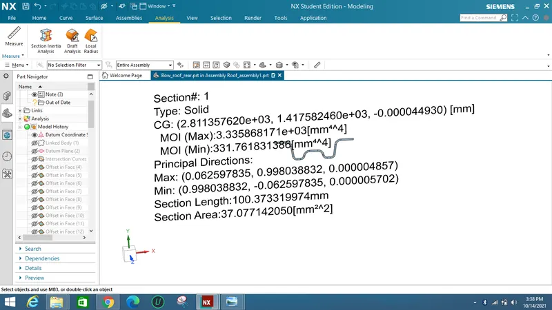
Section Inertia Analysis :
The value at which the load acts effectively is I = 331 mm^4.
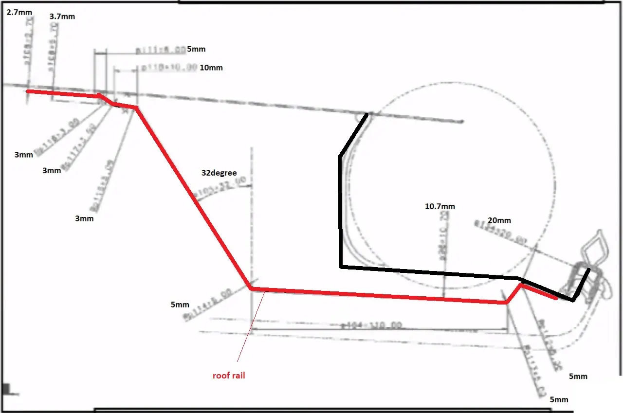
Rear Roof rail Design :
As referring to the Rear rail sketch Front roof rail is designed.
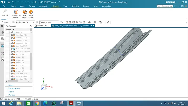
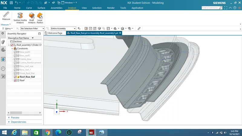
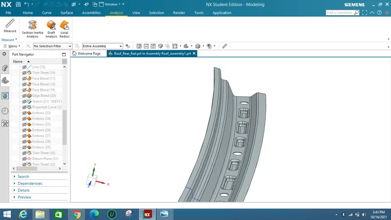
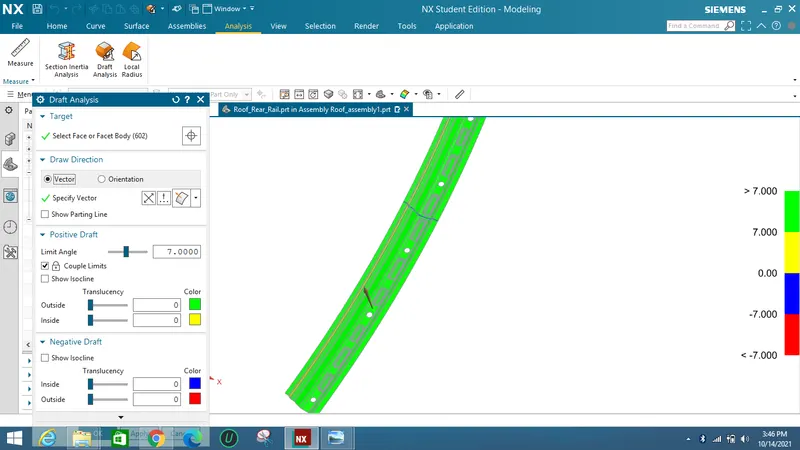
By making offsets and law extensions Roof rail is designed with maintaining of 3 degree draft.
Embosses were added for strengthening the part.
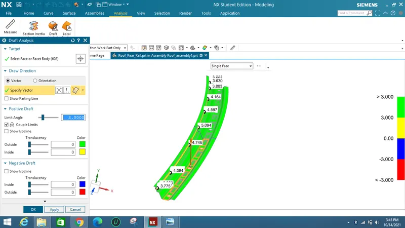
Draft Analysis :
As from the standard sheetmetal criteria a minimum 3 degree of draft angle should be provided on the sheet metal.
Section Inertia Analysis :
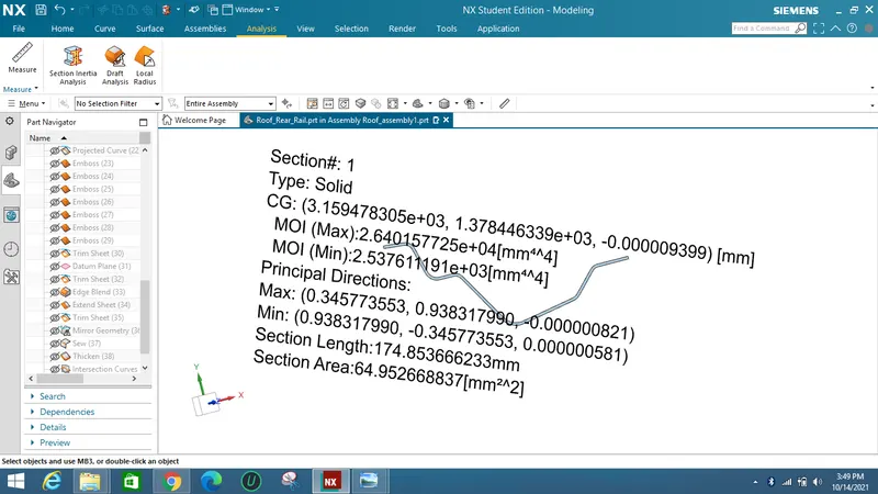
The value obtained where minimum load taking capacity starts is I = 2537 mm^4.
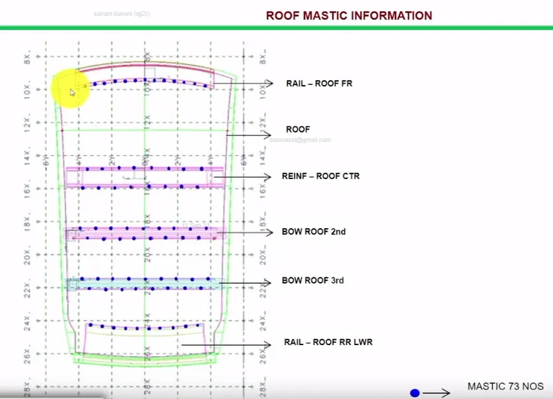
As per the design there should be minimum 5mm gap for mastic points so that roof rails and Bows are attached to roof.
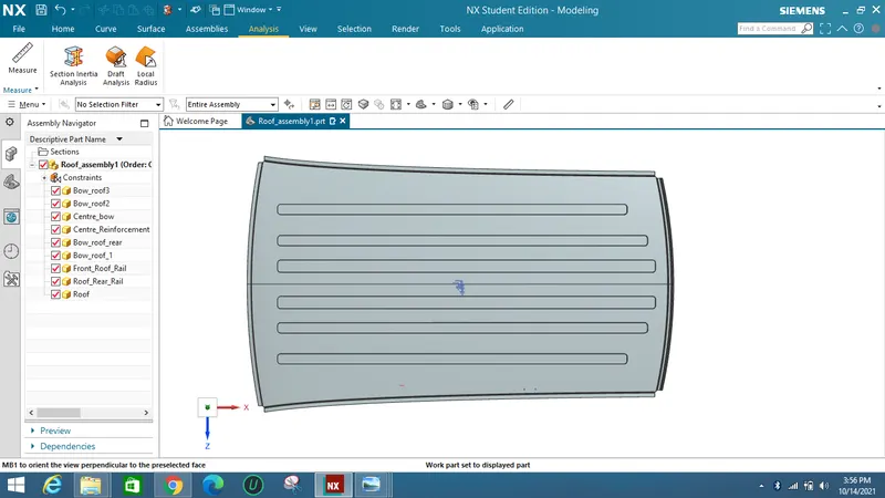
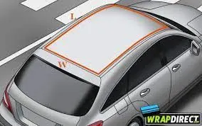
Curvature study on the roof and perform calculations to determine the position of the Bow-roof :
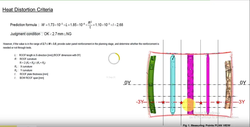
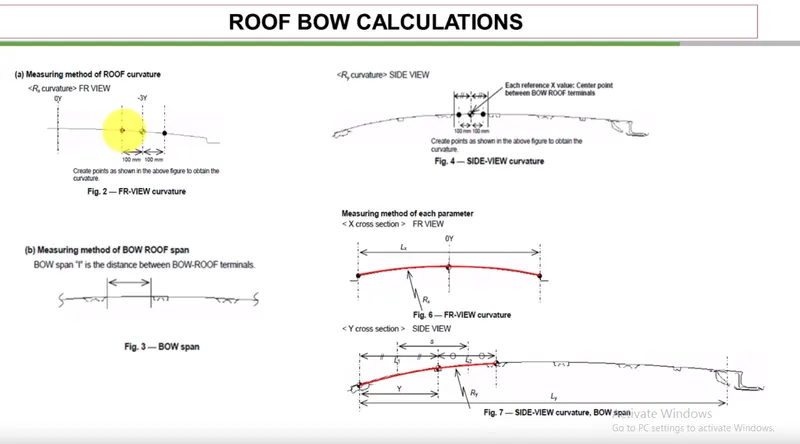
Bow–roof prediction Formula :
W = [1.73 x 10^(-3) x L] + [1.85 x 10^(-8) x (R^2)/t] + [ 1.10x10^(-3) x l] - 2.68
Judgement Condition : OK< 2.7> 3.1
Where
L = Roof Length in X-Direction[mm](Roof dimension in 0-Y)
R = Roof curvature
R = 2(Rx*Ry)/(Rx+Ry)
Rx = X curvature
Ry = Y curvature
t = Roof plate thickness [mm]
l = Bow Roof Span [mm]
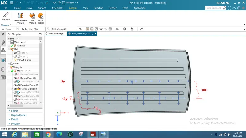
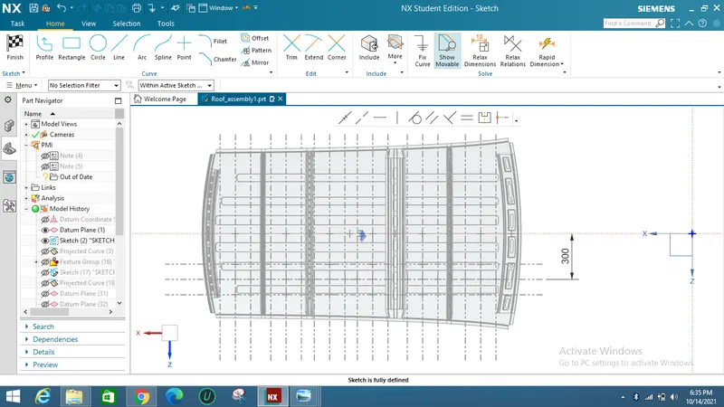
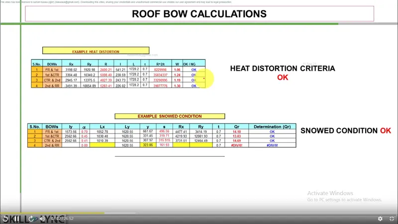
Heat Distortion Results :
For the above given condition the value should be < 3.1 so that the position of bow roofs can be considered as qualified.
The calculated values of Excel sheet is given below :
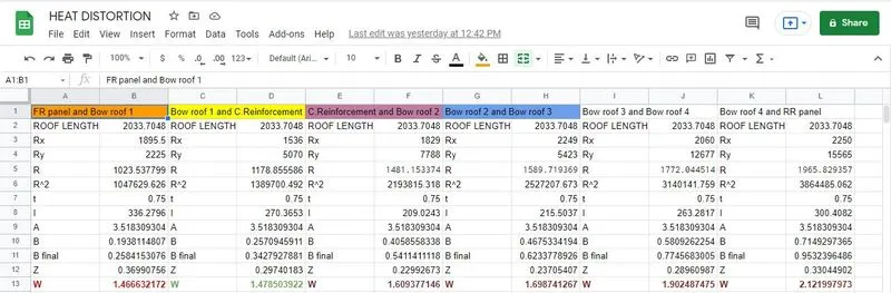
Heat Distortion Excel Sheet Results
Therefore the placement of Bow roofs can be considered for Load Analysis.
SNOW LOAD PREDICTION FORMULA :
Qr = [Iy x t2] / [α x s x [(Rx + Ry)/2]2 x 10-8]
Note: The Qr value given over here is correct. There was a typo error in the formula given in the video.
Where
α = My x Lx2 x 10-12 , My = Y(Ly-Y)
Judgement condition = Qr ≥ 3.1
250 ≤ s ≤ 380
t = Roof plate thickness [mm]
Ly = Distance between the front and rear roof Rails on the Vehicle along with 0Y[mm]
Length of Roof panel with the center point between Roof rail Front /Rear as the front and rear reference point.
Lx = Distance between the Left and Right end of the roof on the Roof BOW [mm]
Width of the roof panel exposed on the surface.
Y = Distance front Front Roof Rail to Roof BOW[mm]
s = Distance for which Roof BOW bears divided load [mm]
s = L1/2 + L2/2
Iy = Geometrical moment of inertia of Roof BOW (Y cross-section )[mm4]
Rx = Lateral direction curvature radius of roof panel Y cross-section on Roof BOW [mm]
Roof panel curvature Radius of the Length Lx in Front view
Ry = Longitudinal Direction curvature radius of the Roof panel X cross-section on Roof BOW [mm]
Roof panel X curvature radius of length s in Side view.
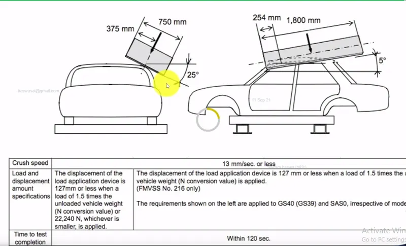
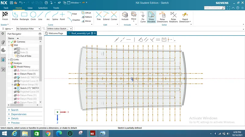
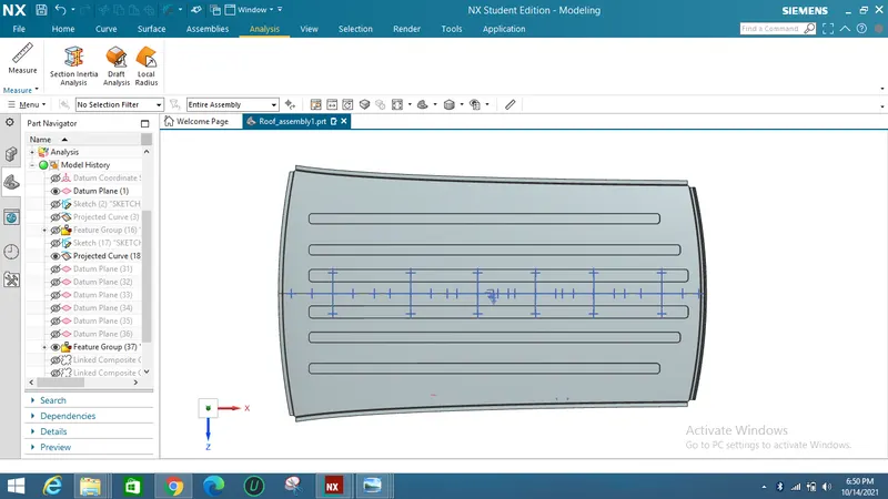
The calculated excel sheet values were shown below :
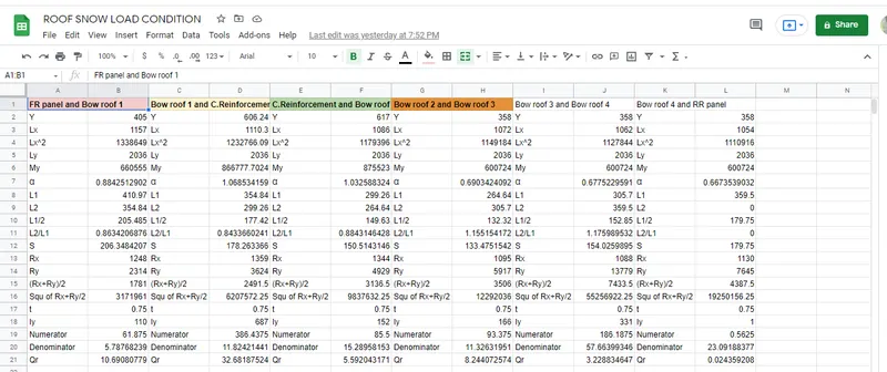
Therefore the Qr values are >3.1 and we can assume that this Roof design can withstand the load conditions and move forward in design and Analysis.
GOOGLE DRIVE LINK :
Zip file for Roof design where assembly and parts were placed :