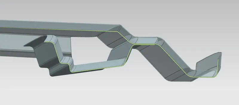
Roof challenge
CAR ROOF ASSEMBLY
The Roof of a Car is one of most important components in a Car. Along with providing a cover over our head from varying weather conditions (which is common knowledge), it serves another very important purpose. That is to provide protection to passengers in case of a Roll-over. So, naturally, this becomes a Critical component. Along with this, the Roof also acts as a bridge between the A-,B- & C-Pillars.
Components
1. Outer Roof Panel -
Outer Roof Panel is the main component that makes up the Roof Assembly. This is mostly an aesthetic component. But few performance cars use this to reduce the Aerodynamic drag to improve their performances.
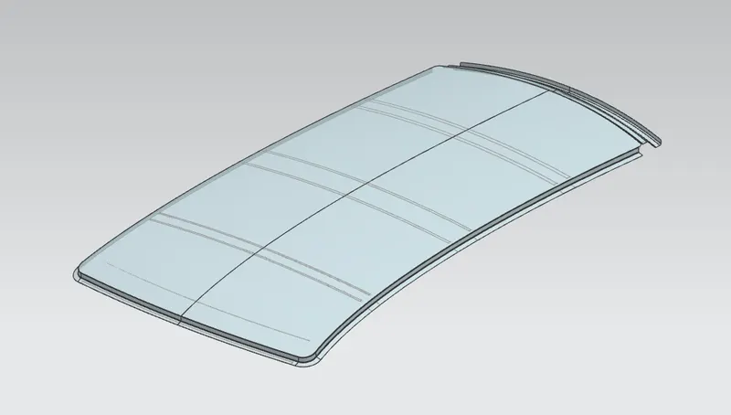
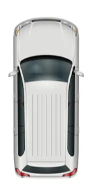
This is a more generic approach to the design. But big cars such as SUVs, Vans have ridges on top to maintain the Structural Rigidity of the Roof.
2. Front Roof Rail -
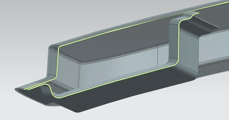
This part of the Roof Assembly connects the front of the car i.e Windshield to the rest of the Roof. During designing this component, we need to take a few things into consideration. They are -
- Visibility Criteria - Visibilty Criteria decides the gap between the outer panel and the Roof rail base. This is an important parameter that needs to be taken care of because it directly affects the Driving comfort and safety.
- Driver Head room Criteria - Head Room is another important aspect that needs to be taken into consideration during designing the Front Roof Rail.
- Windshield Placement - Windshield is slotted directly in between Front Roof Rail and the Outer Panel. So, there should be ample space left for the glass and the sealant positioning.
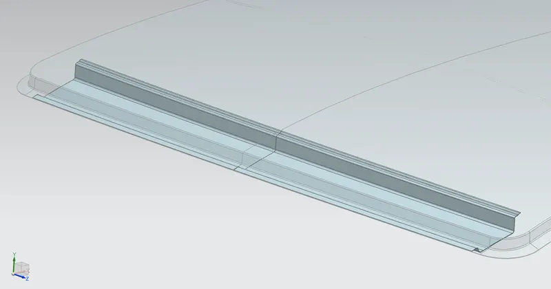
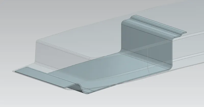
3. Center Reinforcement Rail -
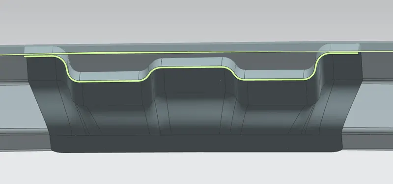
This is the primary Reinforcement of the Roof panel. This is usually provided at the center of the Roof Panel.
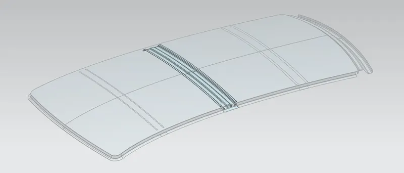
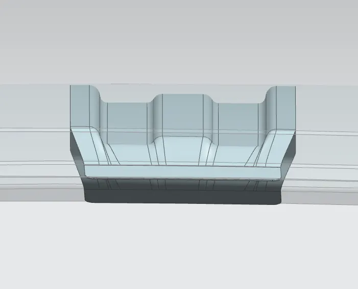
4. Bow Roofs -
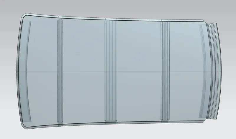
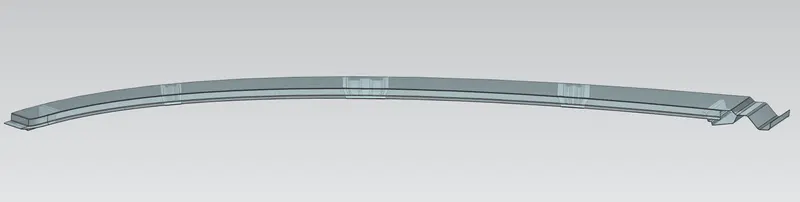
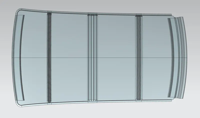
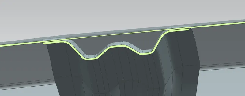
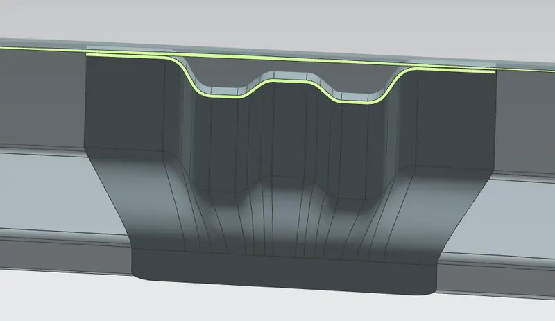
These are the Secondary Reinforcements provided on the Roof panel. These act as supporting members to the main Center Reinforcement provided. Bow Roofs need to be strategically placed on the Roof. The number of Bow roofs depend on the Length of the Roof and its curvature. Initially, the bows are placed at the center between the Center Reinforcement and the Front/Rear Roof Rail. Then using Heat Distortion Criteria, we find out if the position is right. We then adjust them accordingly. The general idea of the placement is that, the flatter the panel the more strength it requires. So, bow roofs are usually placed at the flattest region of the Panels.
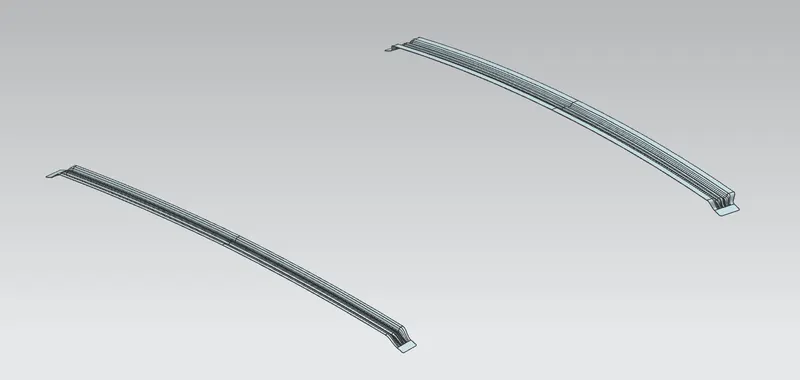
We made use of two Bow roofs in this particular design. To justify this we used Heat Distortion Criteria. It is as follows -
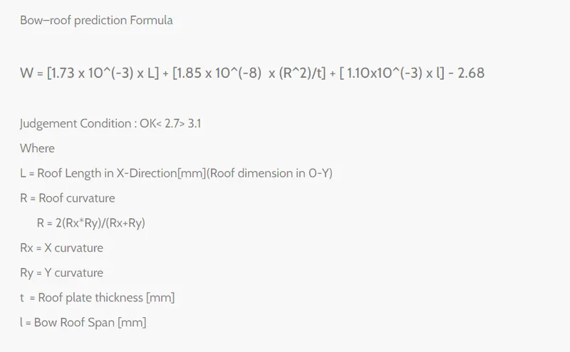
The results have been tabulated as seen below -
| Serial Number | Area of Action | Length (L) | Radius of Curvature (Rx) | Radius of Curvature (Ry) | Actual Radius of Curvature (R) | Bow Roof Span (l) | Thickness (t) | W | OK/NG |
| 1. | FRR - BR1 | 2065.4395 | 3028.4823 | 2116.7907 | 2491.8651 | 281.3047 | 0.75 | 1.635 | OK |
| 2. | BR1 - CRR | 2065.4395 | 2901.6962 | 5608.6855 | 3824.6701 | 441.4727 | 0.75 | 1.739 | OK |
| 3. | CRR - BR2 | 2065.4395 | 4240.0620 | 11259.5113 | 6160.3019 | 463.2058 | 0.75 | 2.338 | OK |
| 4. | BR2 - RRR | 2065.4395 | 4264.1100 | 17465.3298 | 6854.6716 | 312.2099 | 0.75 | 2.395 | OK |
The accepted range is lower then 2.7 mm. As we can see all the values are safely below it and so the bow roof placements satisfy the Heat Distortion Criteria.
Another Criteria called Snow Load Criteria is also used to justify the Bow Placement. It is as follows -
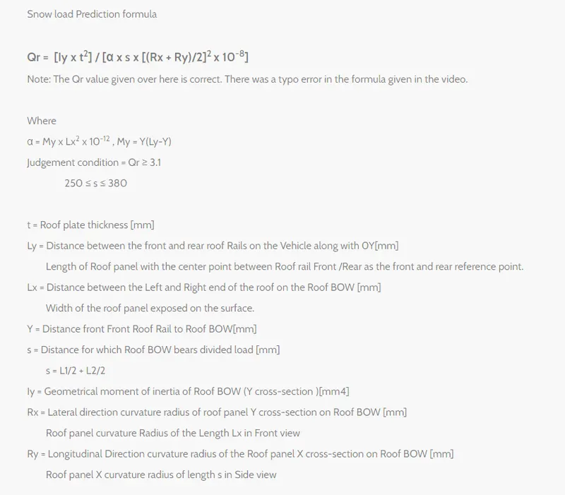
The results have been tabulated as seen below -
| Area of Action | Moment of Inertia (Iy) | Length along Y (Ly) | Length along X (Lx) | Distance between Reinforcements (Y) | Radius along X (Rx) | Radius along Y (Ry) |
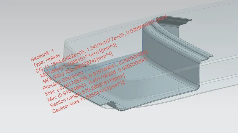
| FRR - BR1 | 729.296 | 2065.4395 | 1030 | 300.230 | 3028.4823 | 2116.7907 |
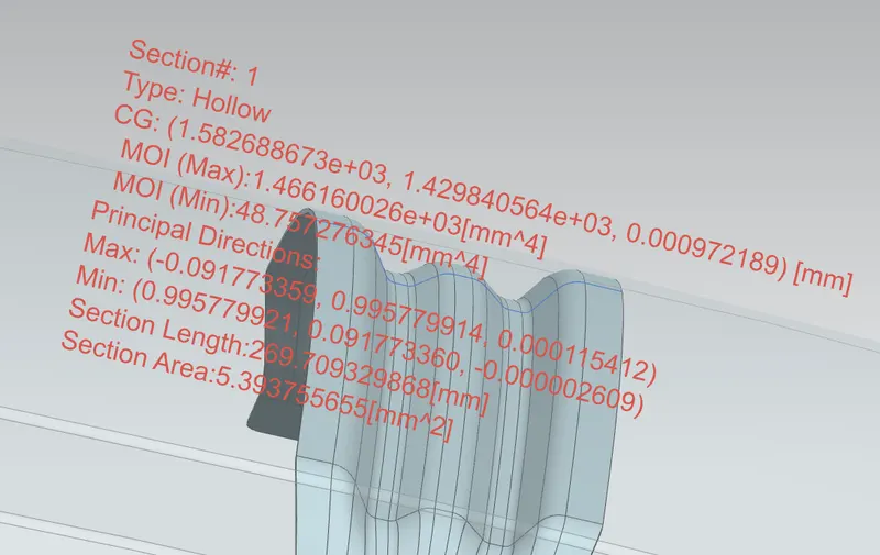
| BR1 - CRR | 214.4279 | 2065.4395 | 1050 | 461.475 | 2901.6962 | 5608.6855 |
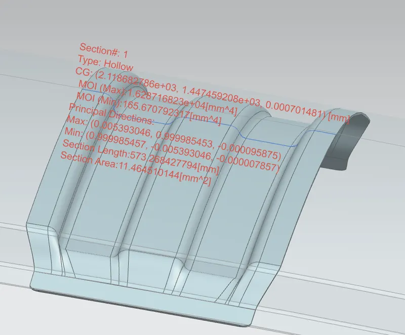
| CRR - BR2 | 1707.03 | 2065.4395 | 1040 | 483.205 | 4240.0620 | 11259.5193 |
| My | L1 | L2 | S = (L1+L2)/2 | Thickness (t) | `alpha` | Qr | OK/NG |
| 529968.8482 | 300.230 | 461.472 | 380.736 | 0.75 | 0.56224 | 28.9550 | OK |
| 740186.0902 | 461.472 | 483.205 | 472.338 | 1 | 0.81605 | 3.172 | OK |
| 764543.6216 | 483.205 | 330.209 | 406.707 | 1 | 0.82693 | 8.451 | OK |
There are two judgement criterion here. S and Qr.
- S needs to be in between 250 & 380. Values of S in all the three areas we chose for this study satisfy this criteria.
- Qr needs to be greater than 3.1. All the values of Qr for our study are greater than 3.1.
So, our Roof satisfies the Snow Loading Conditions as well.
5. Rear Roof Rail -
Rear Roof Rail completes the Roof Design. It connects the Rear end of the car with the Roof. Again, similar to Front Roof Rail we have to take into consideration, the Visibilty Criteria, the Passenger Headroom Criteria. Along with those two we have an extra consideration. That is to make accomodation for the back door hinges and the Sealant.
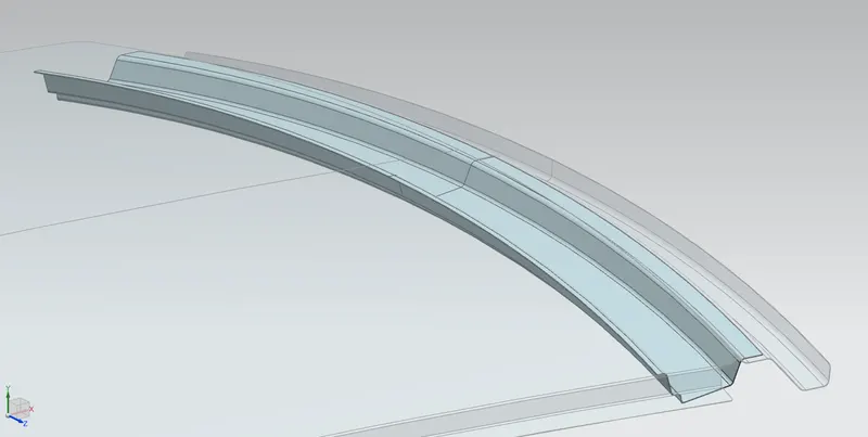
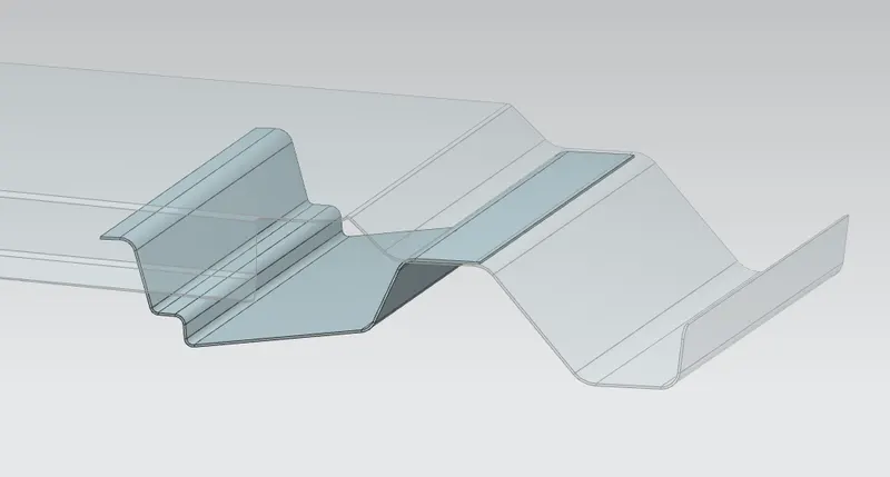
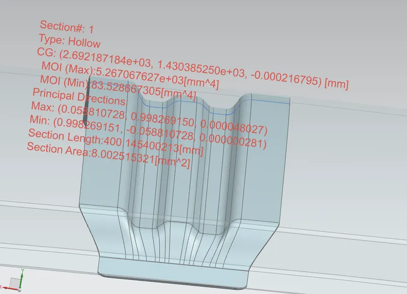
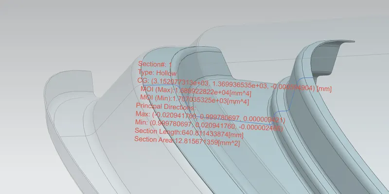
Moment of Inertia of different reinforcements used
Front Roof Rail
Bow Roof 1
Center Roof Reinforcement
Bow Roof 2
Rear Roof Rail
Pictures of different Views of the Assembly
Clip Sections
Front Roof Rail
Bow Roof 1
Center Roof Reinforcement
Bow Roof 2
Rear Roof Rail