Roof challenge
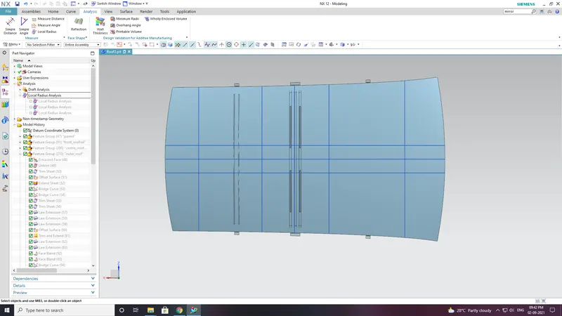
AIM : For the Given Roof styling, Develop the essential flanges and reinforcements, Provide appropriate dimensions and check for Draft analysis, and submit your Section Inertia report on the 0-Y section.Start with the creation of a roof ditch area the tool opening angle is only 3 degrees.Do a curvature study on the roof and perform calculations to determine the position of the Bow-roof
Vehicle mass reduction or lightweighting is an important concept pursued by the automakers since the dawn of the automotive
industry. Lightweighting has many benefits including better acceleration, increased fuel economy, reduced green house gas (GHG)
emissions, better handling, etc. Vehicle performance is sensitive to the power to weight (P/W) ratio. Therefore, reducing weight while
keeping the power constant can drastically improve performance. Also, the fuel economy is improved if the P/W ratio is maintained
by reducing power and weight concurrently. Automakers often find a middle ground between improving performance and fuel
economy
Load Cases
The primary functional requirements for the roof and roof structure are to:
• Provide protection for the occupants from the elements
• Meet federal roof crush regulations (FMVSS 216)
• Contribute to the structural performance of the body
• Contribute to maintaining the dimensional accuracy of the body
Based on the roof structure’s functional requirement, the CALM team selected the following load cases to study for this project:
1. Roof Crush
2. Roof Panel Dent
3. Body-in-White (BIW) bending stiffness and frequency
4. BIW torsional stiffness and frequency
Roof Crush
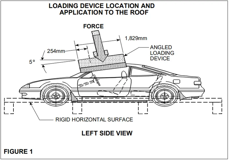
FMVSS 216 - In the test, the strength of the roof is determined by pushing an angled metal plate
down on one side of the roof at a slow but constant speed and measuring the force required to
crush the roof. The force applied relative to the vehicle's weight is known as the strength-to-weight
ratio. The peak Strength-to-Weight ratio (SWR) recorded at any time before the roof is crushed five
inches is the key measurement of roof strength.
SWR value of three and above is considered good by NHTSA.
Roof Dent
A Spherical ball of 25.4mm indented on roof with 150N force and
the response is recorded in terms of resistance force offered and
plastic strain to identify any permanent deformation.
Lower plastic strain value is better as it represents less plastic
deformation.
Bending Static Stiffness: The Body-in-White (BIW) is
constrained at the four shock mounts positions. A load of
1000N applied at rockers.
Bending Frequency: The body has resonant frequencies for
which a small dynamic force at the resonant frequency can
cause large deformations. Although the number of
frequencies is infinite, we will calculate lowest frequency of
bending.
Torsion Stiffness: The BIW is constrained with minimal
boundary conditions, at the middle of the front bumper and at
the rear shock mount. Force of about 1000N is applied in the
opposite direction on the Vertical axis in the shock tower
mount. This will induce a static moment on the front shock
tower with the rear spring mounts constrained in all
translation degree of freedoms.
Torsion Frequency: calculate the lowest frequency (mode) of
torsion.
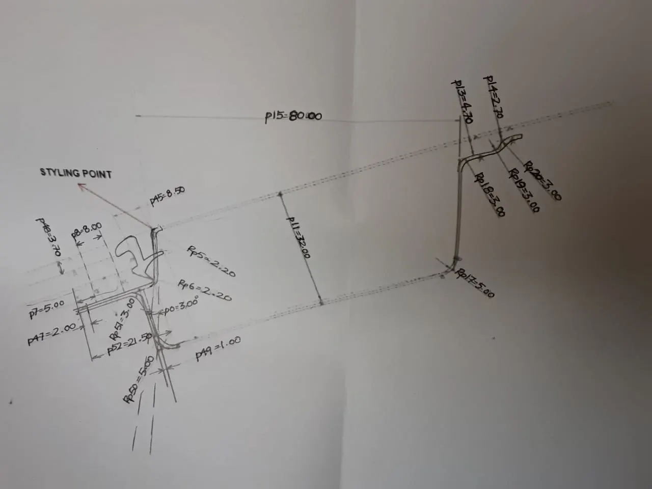
Front roof Rail master section reference image 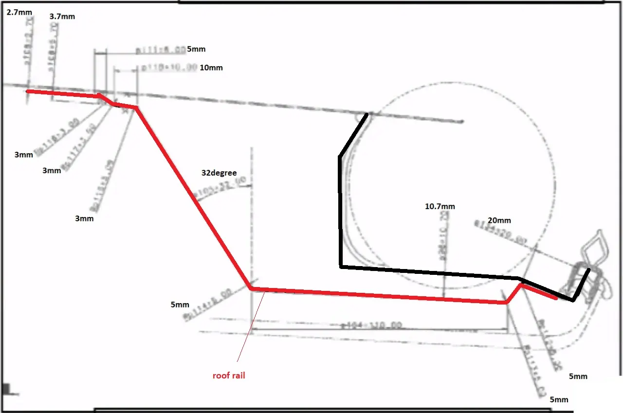
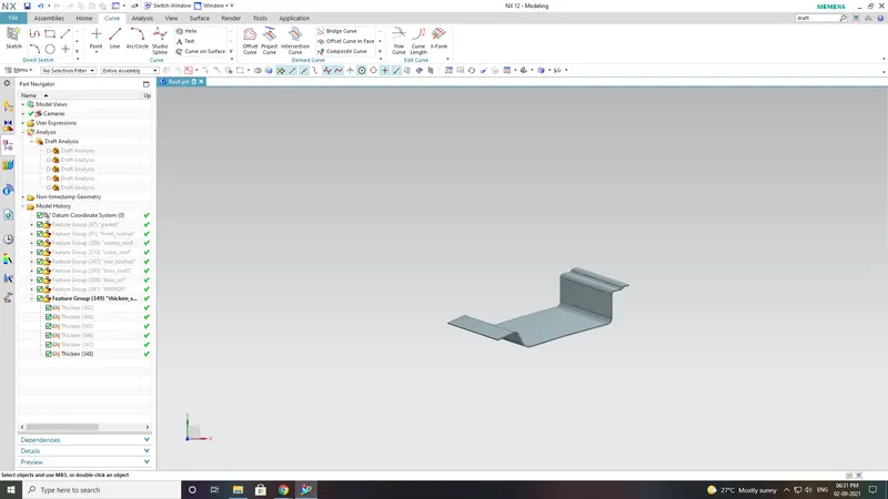
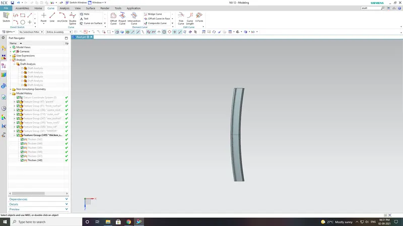
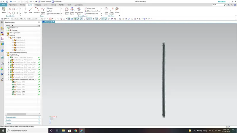
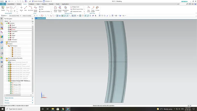
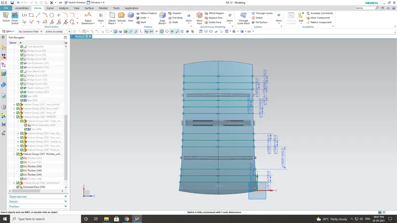
I made the roof with front rail, rear rail, 2 bow roofs, and centre reinforcements.
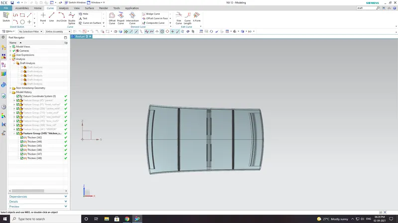
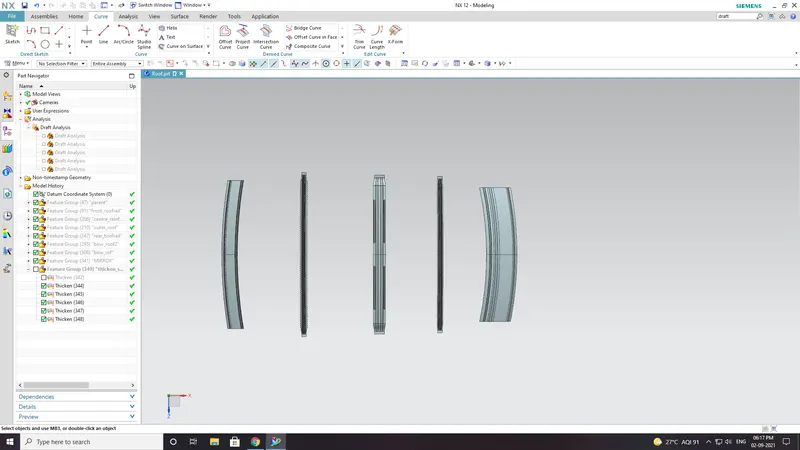
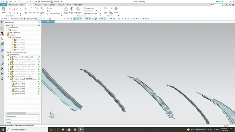
front rail
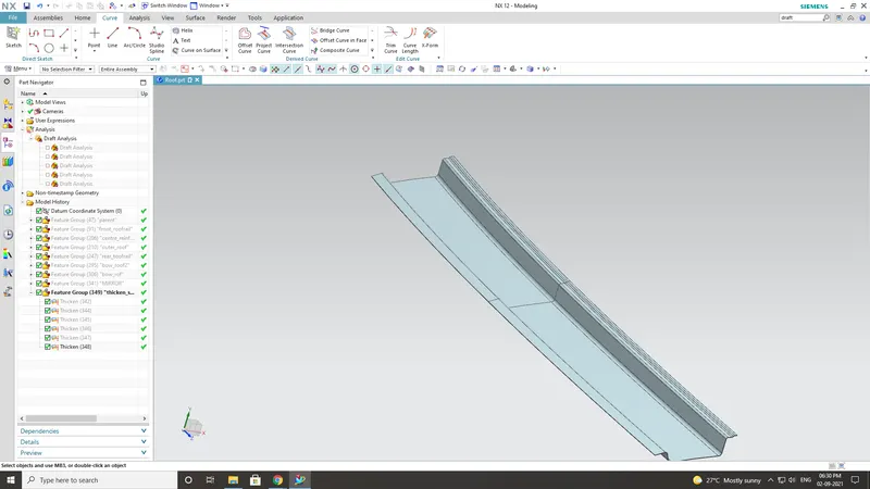
2 bow roofs
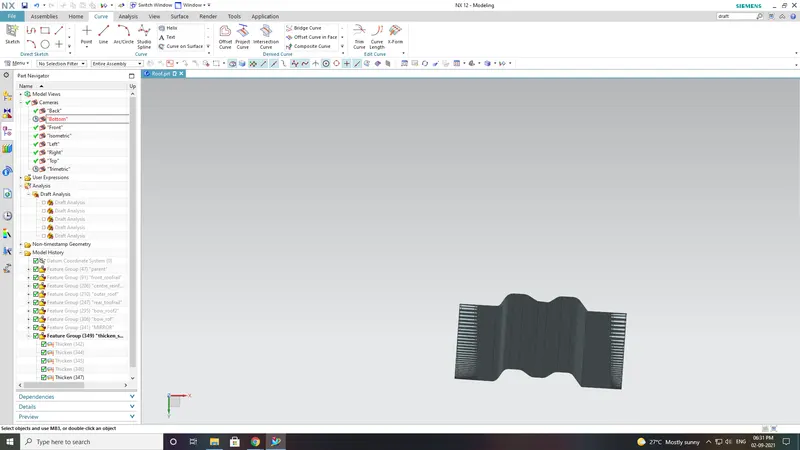
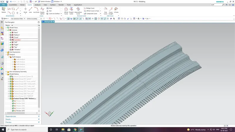
centre reinforcements.
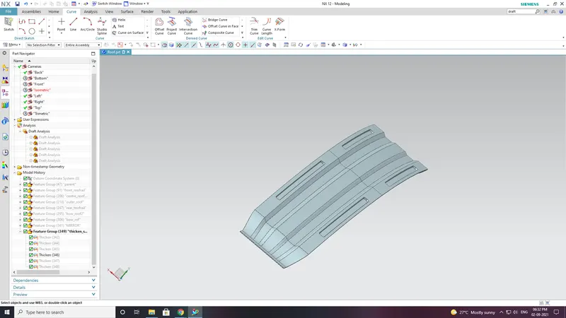
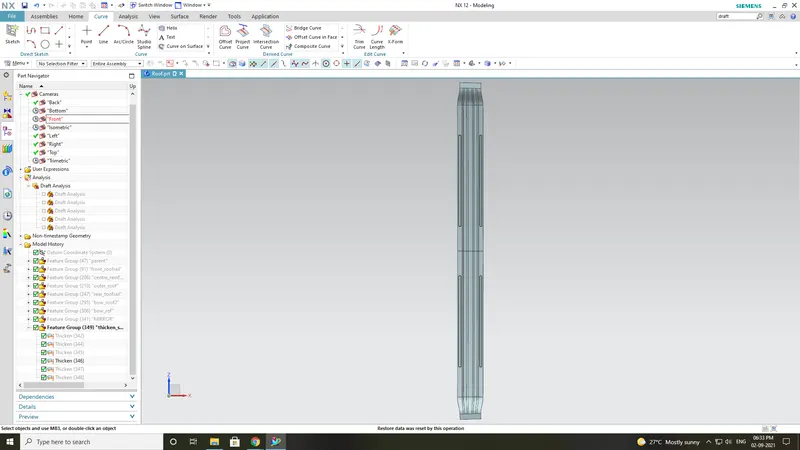
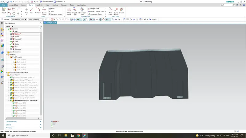
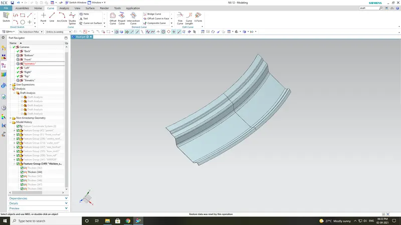
Rear rail
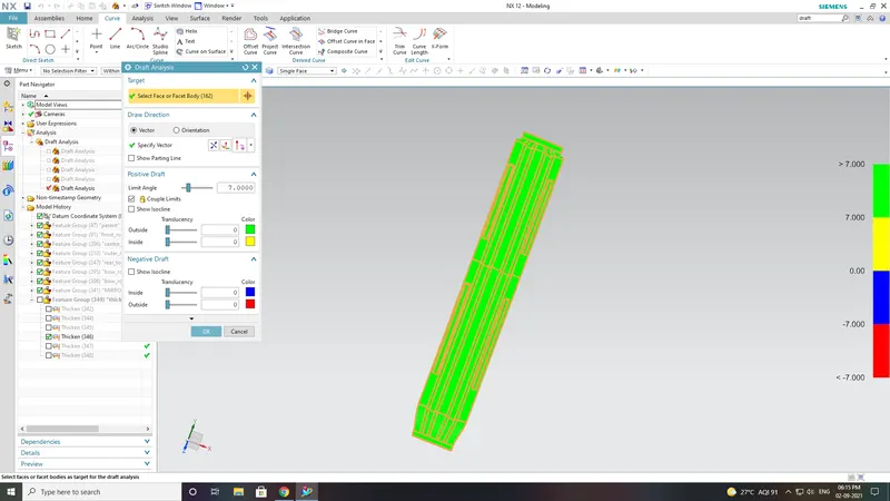
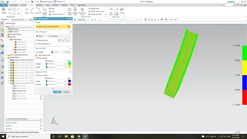
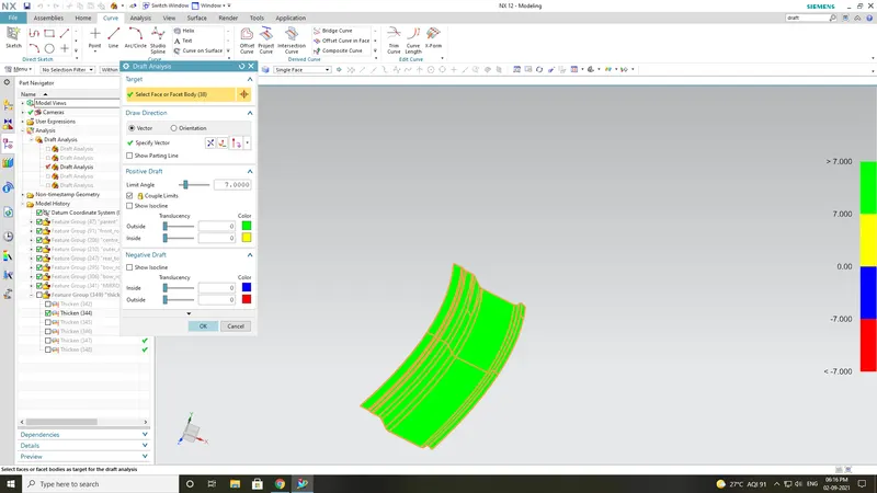
Draft analysis :
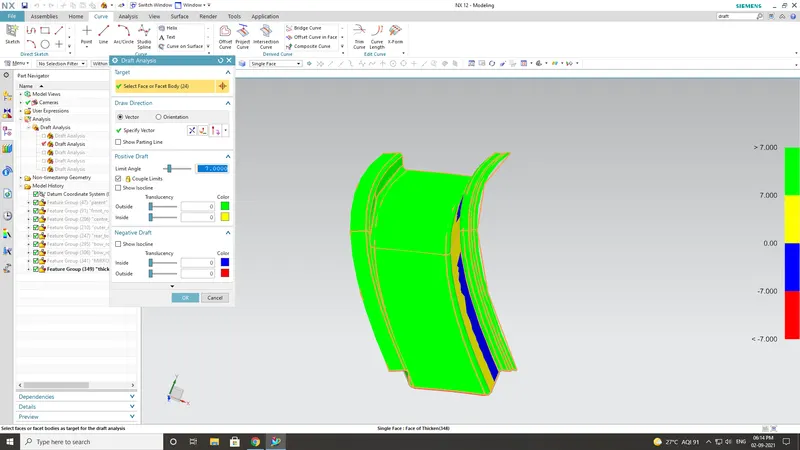
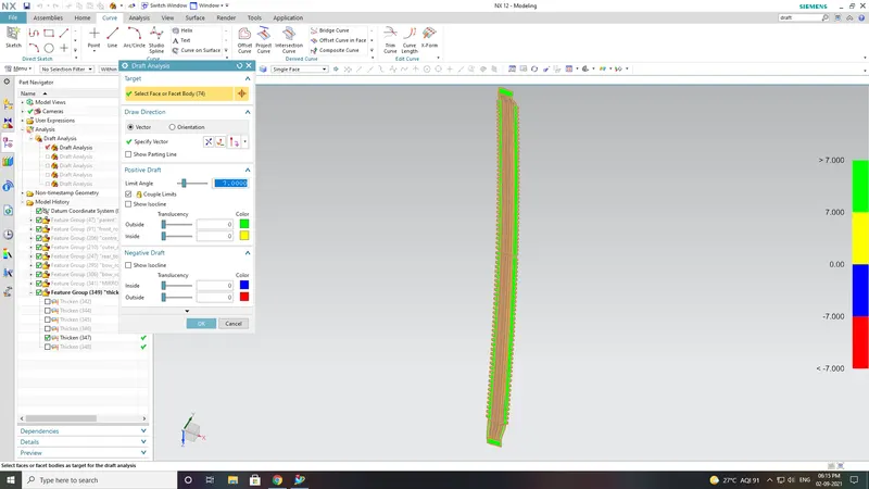
Draft analysis lets you check parts and/or molds, to make sure they will seperate. Hopefully avoiding "locking" the part in the mold (or mould).The Draft Analysis command enables you to detect if the part you drafted will be easily removed. This type of analysis is performed based on color ranges identifying zones on the analyzed element where the deviation from the draft direction at any point, corresponds to specified values.
Section modulus is a geometric property for a given cross-section used in the design of beams or flexural members. Other geometric properties used in design include area for tension and shear, radius of gyration for compression, and moment of inertia and polar moment of inertia for stiffness. Any relationship between these properties is highly dependent on the shape in question. Equations for the section moduli of common shapes are given below. There are two types of section moduli, the elastic section modulus and the plastic section modulus. The section moduli of different profiles can also be found as numerical values for common profiles in tables listing properties of such.
S = I/Y
S = Section Modulus
I = Moment of Inertia
y = distance between the neutral axis and the extreme end of the object
PROCEDURE :
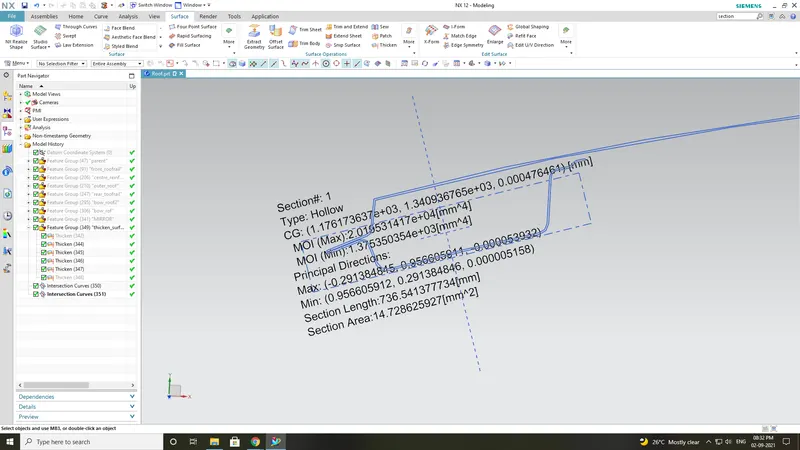
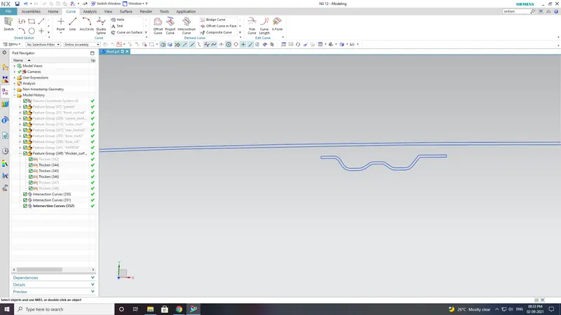
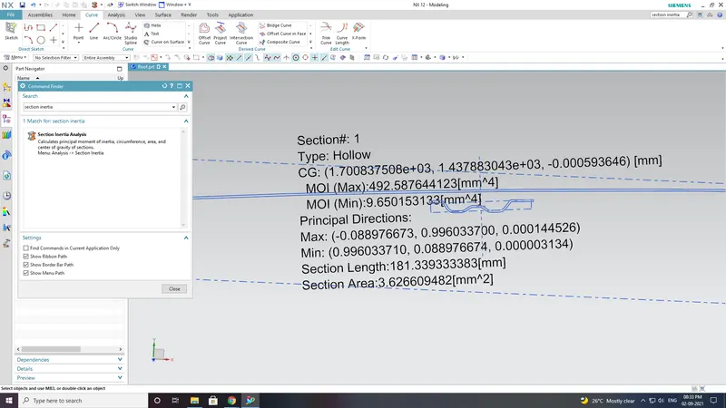
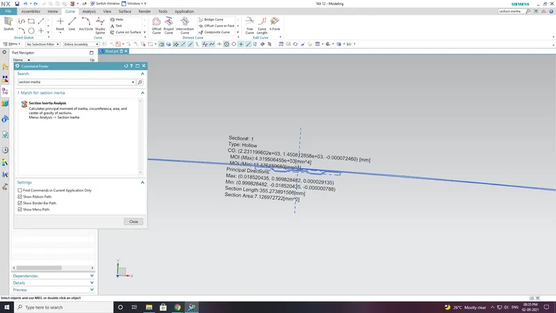
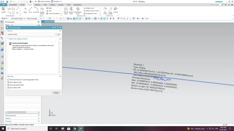
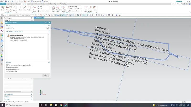
- By using the intersection curve tool on the hood outerand inner panel part design, an intersection curve is created.
- Closing the intersection curve by adding curves and trimming unwanted curves.
Bow–roof rail Formula :
Heat distortion calculations:
W = [1.73 x 10^(-3) x L] + [1.85 x 10^(-8) x (R^2)/t] + [ 1.10x10^(-3) x l] - 2.68
Judgement Condition : OK< 2.7> 3.1
Where
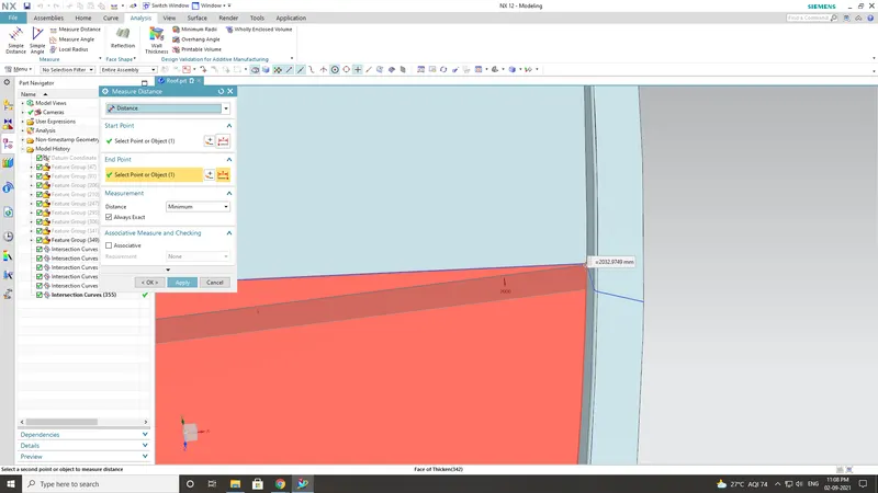
L = Roof Length in X-Direction[mm](Roof dimension in 0-Y)
R = Roof curvature
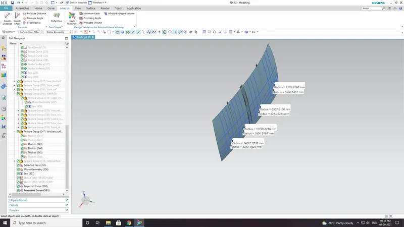
R = 2(Rx*Ry)/(Rx+Ry)
Rx = X curvature
Ry = Y curvature
t = Roof plate thickness [mm]
l = Bow Roof Span [mm]
| Bow |
L (mm) |
Rx(mm) | Ry(mm) | R | t |
L (mm) |
W | Result |
| FR-BOW1 | 2032.0905 | 5598.1487 | 2109.7568 | 3064.5766 | 0.75 | 534.02 | 1.74288 | OK |
| BOW1-BOW2 | 2032.0905 | 4744.5234 | 6352.6106 | 5432.0529 | 0.75 | 464.45 | 2.2303 | OK |
| BOW2-BOW3 | 2032.0905 | 3804.2489 | 10729.8216 | 5616.9997 | 0.75 | 464.73 | 2.265 | OK |
| BOW3-RR | 2032.0905 | 3283.4628 | 14082.2717 | 5325.2703 | 0.75 | 464.93 | 1.923 | OK |
Snow load formula
Qr = [Iy x t2] / [α x s x [(Rx + Ry)/2]2 x 10-8]
Note: The Qr value given over here is correct. There was a typo error in the formula given in the video.
Where
α = My x Lx2 x 10-12 , My = Y(Ly-Y)
Judgement condition = Qr ≥ 3.1
250 ≤ s ≤ 380
t = Roof plate thickness [mm]
Ly = Distance between the front and rear roof Rails on the Vehicle along with 0Y[mm]
Length of Roof panel with the center point between Roof rail Front /Rear as the front and rear reference point.
Lx = Distance between the Left and Right end of the roof on the Roof BOW [mm]
Width of the roof panel exposed on the surface.
Y = Distance front Front Roof Rail to Roof BOW[mm]
s = Distance for which Roof BOW bears divided load [mm]
s = L1/2 + L2/2
Iy = Geometrical moment of inertia of Roof BOW (Y cross-section )[mm4]
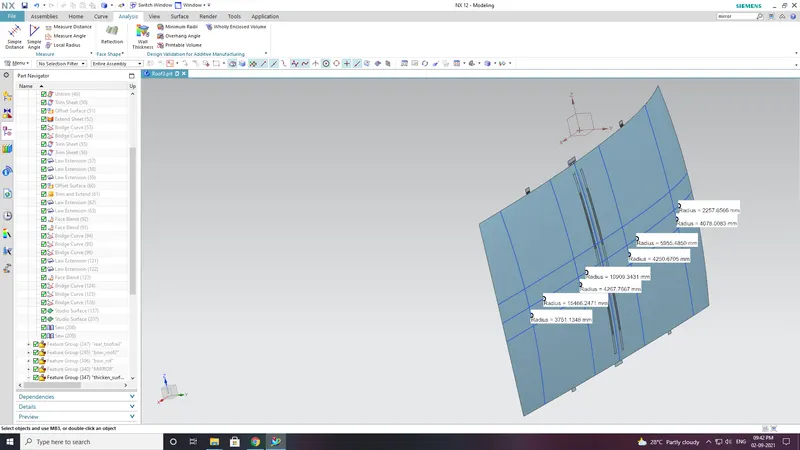
Rx = Lateral direction curvature radius of roof panel Y cross-section on Roof BOW [mm]
Roof panel curvature Radius of the Length Lx in Front view
Ry = Longitudinal Direction curvature radius of the Roof panel X cross-section on Roof BOW [mm]
Roof panel X curvature radius of length s in Side view
| Bow | Ly(mm^4) |
L1 (mm) |
L2 (mm) |
Lx (mm) |
Ly (mm) | Rx (mm) | Ry (mm) | t (mm) | y (mm) | s | a | Qr | Result | |
| FR-BOW1 | 5.570465948 | 15684598 | 499.33044 | 1150.6504 | 2034.4568 | 4078.0083 | 2257.6566 | 0.75 | 1462.5298 | 928.325 | 1.08 | 0.02 | NG | |
| BOW1-BOW2 | 5.558227306 | 499.30284 | 499.45304 | 1052.7781 | 2032.5468 | 4250.6705 | 5955.4850 | 0.75 | 433.302 | 433.345 | 0.88 |
0.025 |
NG | |
| BOW2-BOW3 | 5.54369477 | 499.33044 | 1473.7035 | 1057.2984 | 2034.5678 | 4267.7667 | 10909.3431 | 0.75 | 455.256 | 984.25 | 0.88 | 0.0005 | NG |