Roof Design
Aim: To design the Car Roof and develop the necessary reinforcements by following the Master section and creating a proper assembly with its curvature study.
Project Overview:
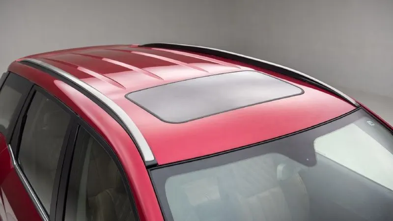
Roof is the component of the car which mounts above the passengers. It is used to protect the passengers from sun, rain, dust, wind, etc. It also provides roll over protection to the passengers. In this project we are going to design the roof outer panel, front roof rail, rear roof rails, bow roofs and reinforcement centre from the given Class-A surface. We will follow the design rules and create the roof assembly as per industry standards. We will verify that the position of reinforcements is as per the heat distortion criteria and snow load criteria. We will also perform draft analysis on all the components and create a section modulus wherever needed.
Theory:
Roof:
An automobile roof or car top is the portion of an automobile that sits above the passenger compartment, protecting the vehicle occupants from sun, wind, rain, and other external elements.
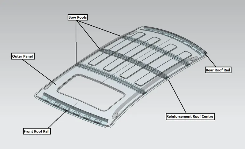
The roof is provided with reinforcements which improves its strength and stiffness minimizing its failure under different load conditions like the roll over accidents, crushing of roof under any calamities,etc. These reinforcements are:
- Front Roof Rail- Along with improving strength it provides space for room lamp mounting and also joins windshield and outer body of the roof.
- Rear Roof Rail- It joins back door to the outer body of the roof.
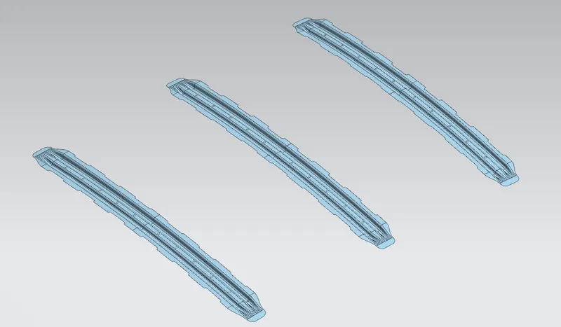
- Bow Roofs(1,2,3)- These components are mainly for improving strength of the roof. In our case as we have sunroof in the design, the bow roof 2 is in association with the reinforcement roof centre. Otherwise the bow roof can be installed infront or behind the reinforcement roof centre as per requirements.
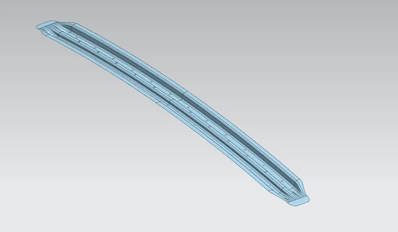
- Reinforcement Roof Centre- Serves the purpose of improving strength and also provides mounting of bracket for room lamp.
Heat Distortion Criteria:
Heat Distortion is the temperature at which the metal softens and deforms under a specific load. In order to minimize this effect and increase local strength of the roof we provide necessary reinforcements. The position of these reinforcements is predicted using the heat distortion criteria.
The Prediction Formula:
W = [1.73 x 10^(-3) x L] + [1.85 x 10^(-8) x (R^2)/t] + [ 1.10x10^(-3) x l] - 2.68
Where,
L= Roof Length in X-Direction
R = Roof curvature
Rx = X curvature
Ry = Y curvature
t = Roof plate thickness
l = Bow Roof Span ( Distance between two bow roofs)
The Judgement Criteria:
W < 2.7
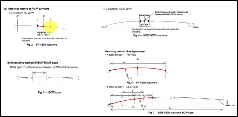
Fig:Curvature Measurement
Source: Skill Lync
Snow Load Criteria:
In cold regions, the roof experiences load due to accumulation of snow. In order to ensure the roof strength at primary stage any roof design has to undergo this criteria.
The Prediction Formula:
Qr = [Iy x t2] / [α x s x [(Rx + Ry)/2]2 x 10-8]
Where
α = My x Lx2 x 10-12
My = Y(Ly-Y)
t = Roof plate thickness [mm]
Ly = Distance between the front and rear roof Rails on the Vehicle along with 0Y[mm]
Length of Roof panel with the center point between Roof rail Front /Rear as the front and rear reference point.
Lx = Distance between the Left and Right end of the roof on the Roof BOW [mm]
Width of the roof panel exposed on the surface.
Y = Distance front Front Roof Rail to Roof BOW[mm]
s = Distance for which Roof BOW bears divided load [mm]
s = L1/2 + L2/2
Iy = Geometrical moment of inertia of Roof BOW (Y cross-section )[mm4]
Rx = Lateral direction curvature radius of roof panel Y cross-section on Roof BOW [mm]
Roof panel curvature Radius of the Length Lx in Front view
Ry = Longitudinal Direction curvature radius of the Roof panel X cross-section on Roof BOW [mm]
Roof panel X curvature radius of length s in Side view
Judgement Criteria:
Qr ≥ 3.1
250 ≤ s ≤ 380
Mastic Sealants:
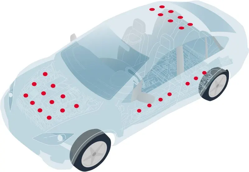
- Mastic sealant is the paste used to join two components where welding is not suitable.
- Once applied and cooled it hardens, joining the components firmly.
- This paste improves the local strength of the component of about 80 mm diameter. We apply these sealants in such a way that the maximum area of the component is covered.
- In roof assembly the mastic sealants are applied between the outer panel and the bow roofs as well as the front roof rail and the rear roof rail.
Design Approach:
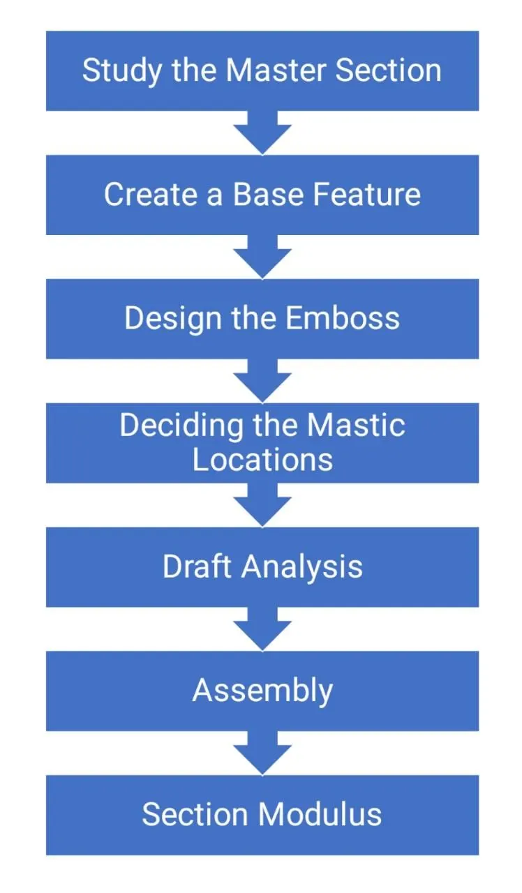
Procedure:
I] Studying the Master Section:
Master Section:
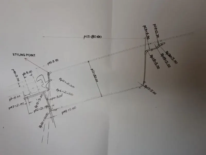
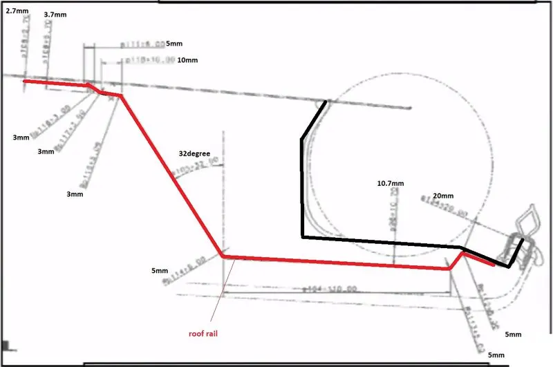
Thickness of all the components = 0.75 mm
II] Creating the reinforcements ( Using Top to down Approach )
- Offset the Class-A to required distance.
- Ensure minimum draft of 3-5 deg is given on the components.
- Removing excess material from the components
- Creating emboss where ever required to strengthen the part.
- Providing necessary fillets on the edges.
- Thicken the surfaces created.
- Perform Draft Analysis on each component.
- Perform Section Inertia Analysis on each component.
Front Roof Rail
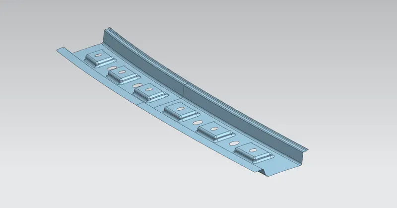
Rear Roof Rail
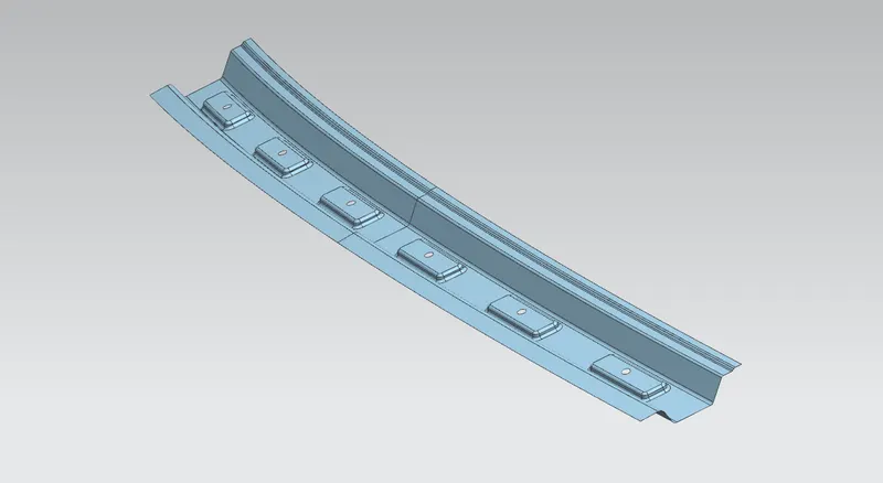
Bow Roofs
Reinforcement Roof Centre
III] Draft Analysis of of the component:
- Draft analysis is performed on the sheet metal component to ensure that there are no undercuts / negative drafts on the component.
- If there are any of these negative drafts the component is not manufacturable.
- This Analysis is performed by the design engineers which helps in eliminating major defects / errors at the very beginning of any product design.
- The Draft of about 7 deg to 25 deg is given on the Sheet Metal Components.
- Minimum Draft of 5 deg is acceptable.
Procedure to perform draft analysis:
- Create a datum coordinate system on the flat surface.
- Check the Deep drawing angle.
- Open the Draft Analysis Tool.
- Select the Perpendicular axis to the flat surface from the newly formed CS.
- Select the component on which we have to perform the draft analysis.
- Click on Ok to obtain the results.
NOTE:
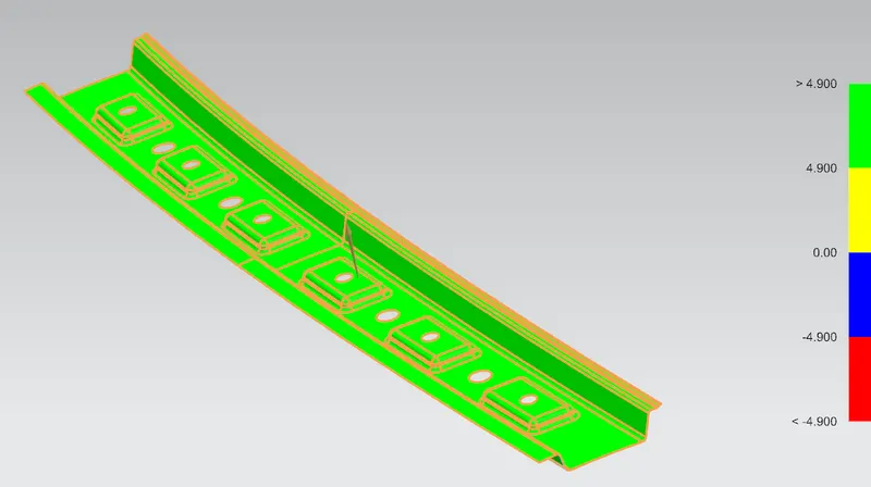
- Maximum portion should be Green as per the color code shown on the RHS of the screen.
- In some cases Yellow patches are accepted but it is a good practice to try to eliminate these patches.
- There should be no Blue or Red patch on the component.
IV] Section Modulus :
- Create a Datum Plane passing through the Assembly
- Using the Intersection Curve Tool create an intersection curve of the assembly
- Project this curve in a sketch and create a continuous outer curve from the projected one.
- Lastly use the Section Inertia Analysis Tool to obtain the results.
Results:
Draft Analysis:
Front Roof Rail
Rear Roof Rail
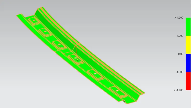
Bow Roofs
Bow Roof 1:
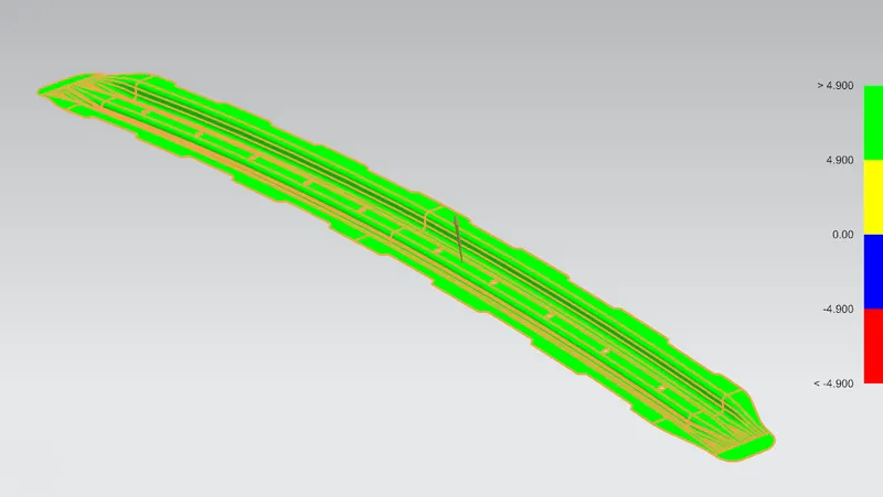
Given Draft angle- 8 deg ( didn't clear at 5 deg)
Bow roof 2:
Given Draft angle- 8 deg ( didn't clear at 5 deg)
Bow roof 3:
Given Draft angle- 9 deg ( didn't clear at 5 deg)
Reinforcement Roof Centre
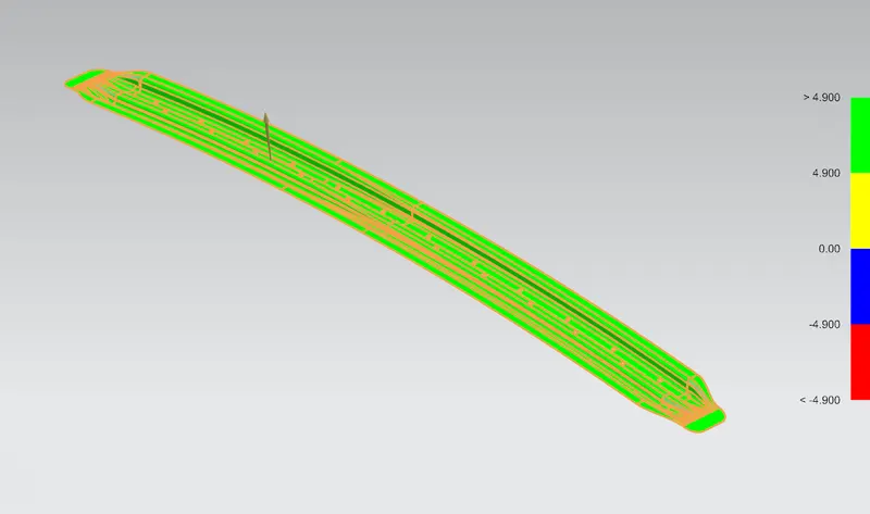
Given Draft angle- 8 deg ( didn't clear at 5 deg)
Section Inertia Analysis:
Front Roof Rail
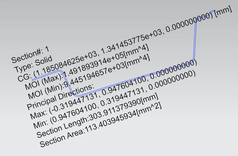
Rear Roof Rail
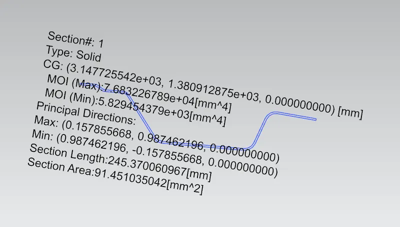
Bow Roofs
Bow Roof 1:
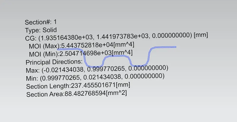
Bow Roof 2:
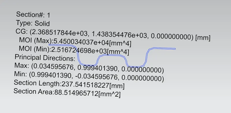
Bow Roof 3:
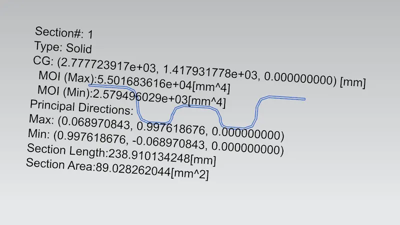
Reinforcement Roof Centre
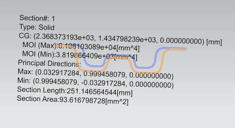
Joint Section For Snow Load Criteria
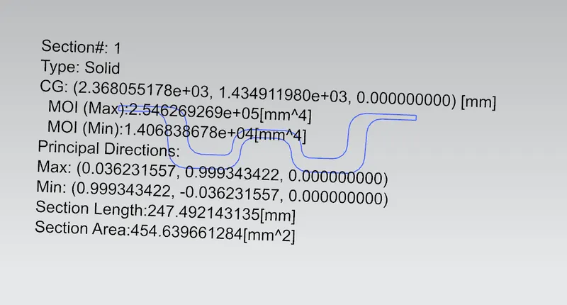
Full Master Section:
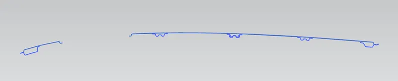
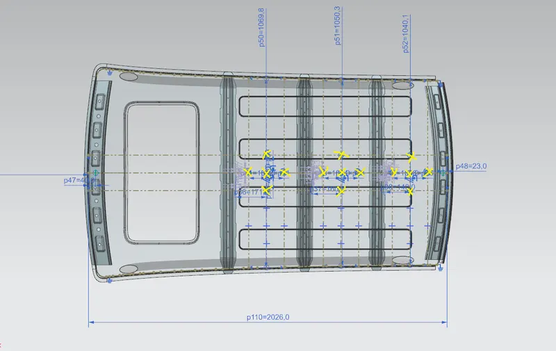
Heat Distortion Criteria:
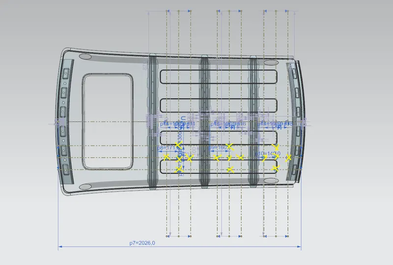

Snow Load Criteria:

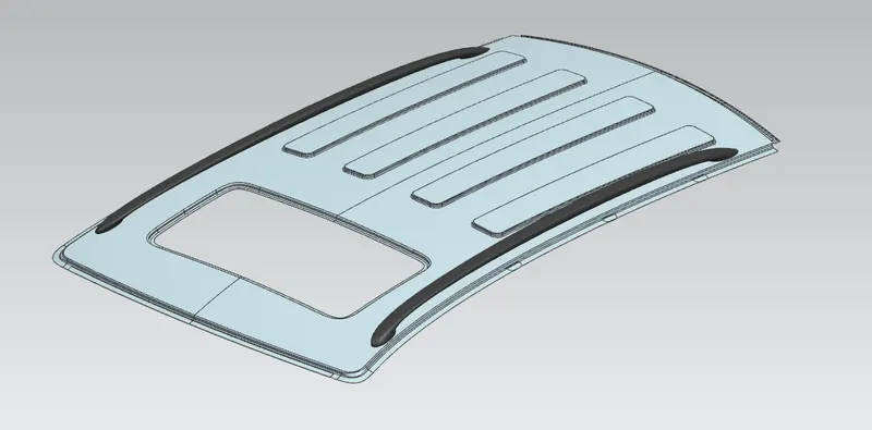
Isometric View:
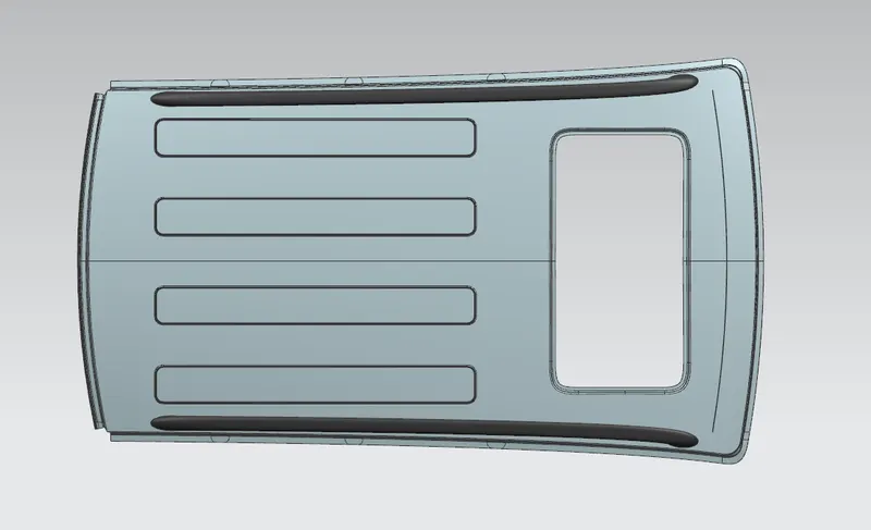
Top View:
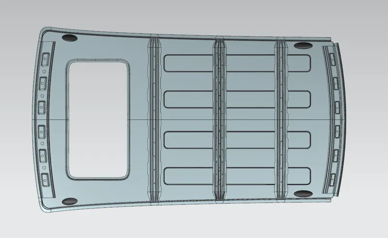
Bottom View:
Conclusion:
Hence we have designed the Car Roof and developed the necessary reinforcements by following the Master section and creating a proper assembly with its curvature study. We can also conclude that the bow roof positions is satisfactory.