Roof challenge
Aim:
To design the Roof with required flanges, reinforcements such as (Front roof rail, Rear roof rails, Bow roof rails and centre roof rail reinforcement). After the initial design has been carried out successfully a curvature study on the roof has to be done to validate the design by applying the heat distortion criteria and snow Load criteria. Section modulus and draft analysis are performed which in detail is explained in the report.
Introduction:
An automobile roof or car top is the portion of an automobile that sits above the passenger compartment, protecting the vehicle occupants from sun, wind, rain, roll-over, and other external elements.
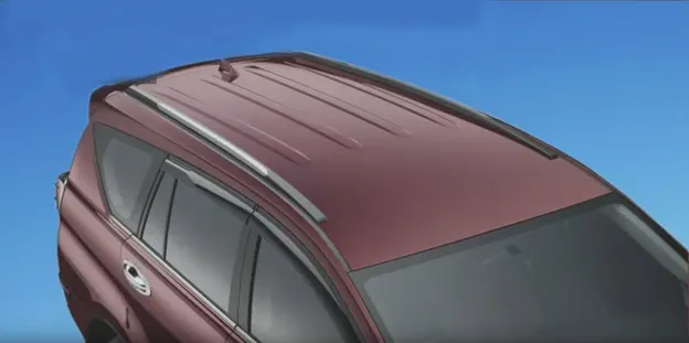
The skin of the roof is a styling surface that are supported by the reinforcements as shown in the image below to provide it strength and stiffness. The reinforcements are joined to the ditch area with a spot weld where it's not the styling zone and with the mastic seals where it is a styling zone.
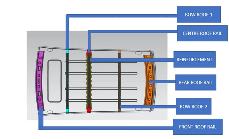
Designed Using Siemens NX
Factors to be remembered before proceeding with the design are
- Minimum tool opening angle 3 Degrees.
- Headroom clearance
- Back door assembly
- Visibility criteria
- Windshield assembly
Procedure
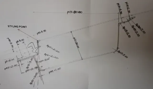
Master section
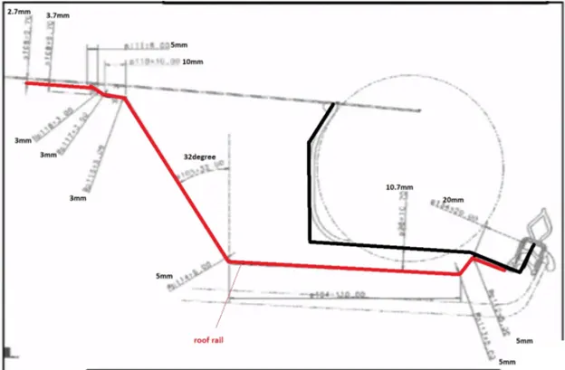
Master section
1) Outer Panel
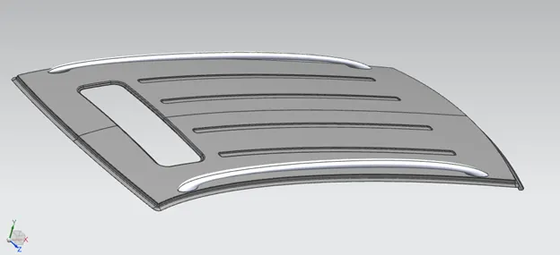
Outer panel designed using Siemens NX
With the given master section and the skin data given by the styling team we can design the flange and the ditch area in the roof with the 3-degree opening angle for tool opening angle.
Draft Analysis
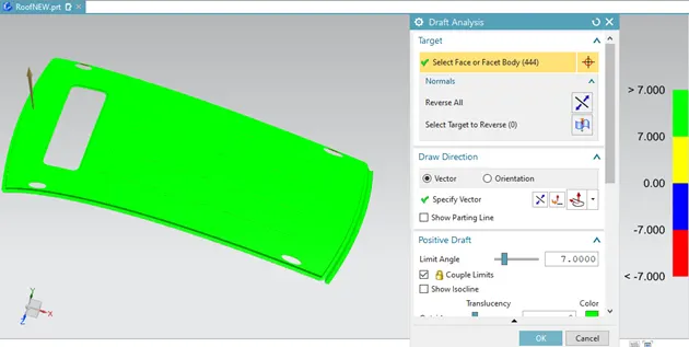
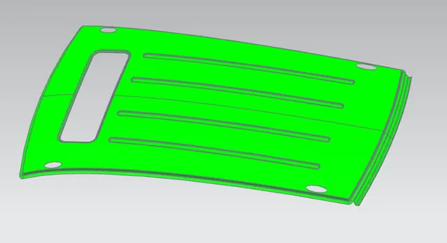
Draft Analysis of the outer roof
- Draft Analysis of the roof outer panel is carried out to check if there is any negative draft in the designed model and if the negative draft exists then it indicates that it cannot be manufactured.
2)Front roof rail
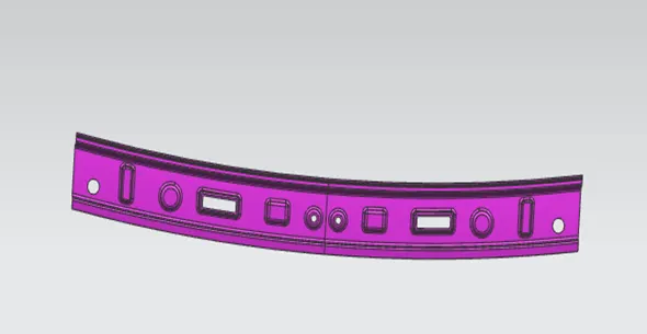
Front roof rail
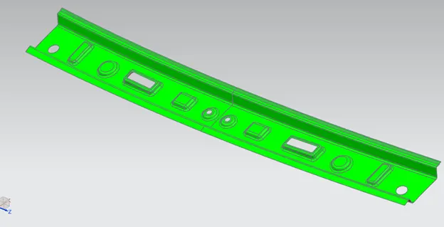
The front roof rail is designed at the front side of the roof following the master section as shown above to provide strength to the roof. Visibility and Head room clearance must be considered while designing the front roof rail.
Example of the Design consideration for front roof rail.
- The embosses are provided inwards as shown in the image so as it doesn’t block the view of the driver.
- 5mm space must be provided between the outer panel and the front roof rail.
- 0.75mm thickness must be considered
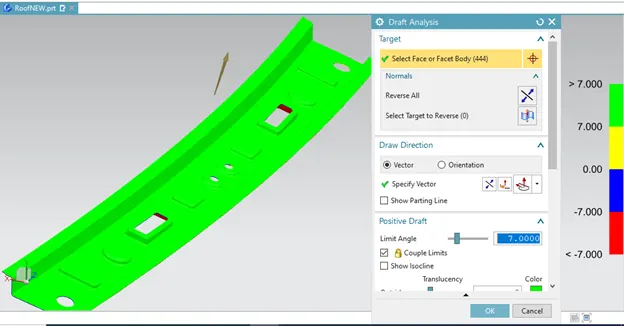
Draft Analysis
Front roof rail
- Draft Analysis of the front roof rail carried out to check if there is any negative draft in the designed model and if the negative draft exists then it indicates that it cannot be manufactured
3)Bow Roof 1 &2
Bow roof -1

Bow roof-2
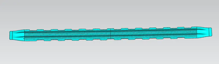
Similarly, the bow roofs are also provided to strength the roof, 5mm space must be provided between the outer panel and the bow roof for the mastics.
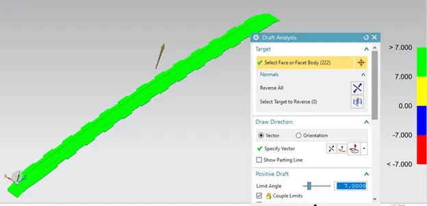
Draft Analysis
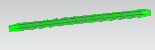
Bow roof-1
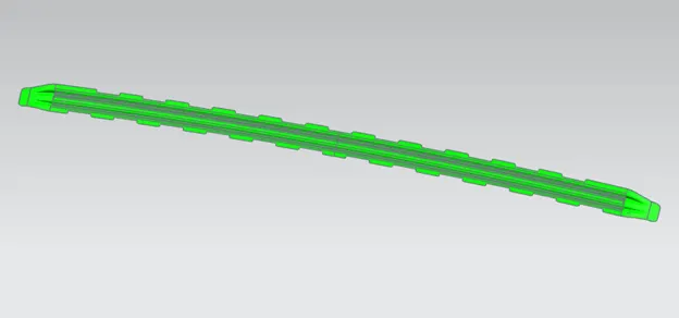
Bow roof-2
- Draft Analysis of the bow is carried out to check if there is any negative draft in the designed model and if the negative draft exists then it indicates that it cannot be manufactured.
4) Centre roof rail and the Reinforcement
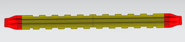
It does the same job as that bow roof, the front roof rail, and the rear roof rail.
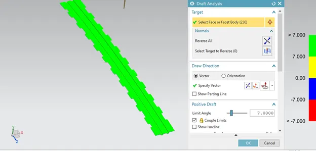
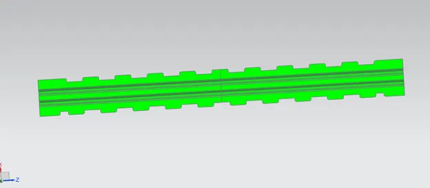
Draft Analysis
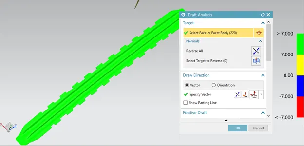

Centre roof rail
Reinforcement
- Draft Analysis of the centre roof rail & Reinforcement is carried out to check if there is any negative draft in the designed model and if the negative draft exists then it indicates that it cannot be manufactured
5)Rear roof rail
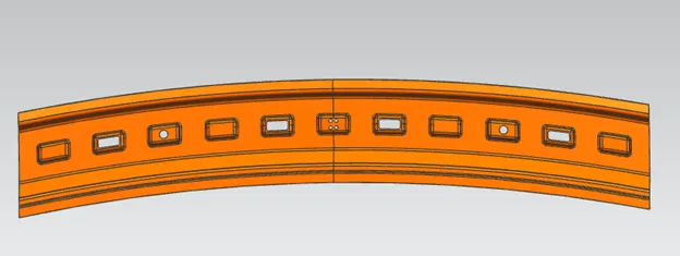
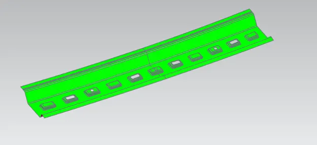
The Rear roof rail is designed at the back side of the roof following the master section to provide strength to the roof. Visibility and Head room clearance must be considered while designing the Rear roof rail.
Example of the Design consideration for rear roof rail.
- The embosses are provided inwards as shown in the image so as it doesn’t block the view of the driver.
- 5mm space must be provided between the outer panel and the front roof rail for mastics.
- 0.75 thickness must be considered.
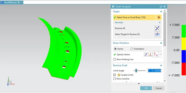
Rear Roof Rail
- Draft Analysis of the rear roof rail is carried out to check if there is any negative draft in the designed model and if the negative draft exists then it indicates that it cannot be manufactured.
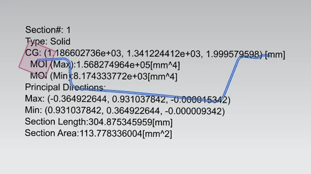
Section Modulus
- It is the ratio of total moment resisted by the section to the distance from the neutral axis to the outer surface.
- It gives us an idea about how much of load the given structure can take.
- if the section modulus increases the moment of resistance increases and hence its load bearing capacity.
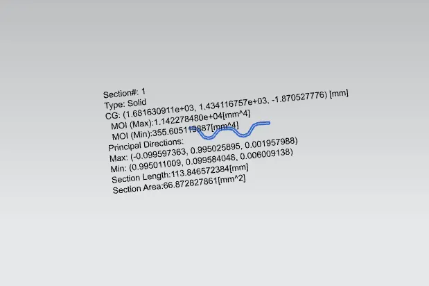
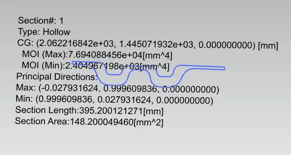
Then the value can be used to find out the section modulus. using the formula given S = I / y
where,
S- Section Modulus
I - Moment of inertia value from the inertia analysis
y - Distance from neutral axis to outermost surface. In this case we will take it from the centre to the outer edge of hemmed outer panel.
FRONT ROOF RAIL
BOW ROOF RAIL -1
CENTRE ROOF RAIL
BOW ROOF-2
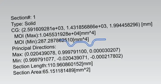
REAR ROOF RAIL
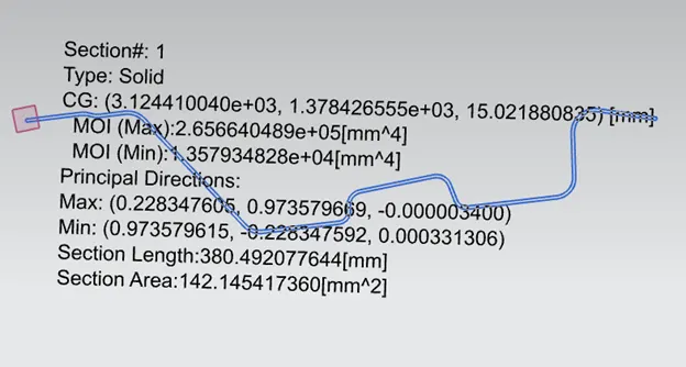
Result of Section Modulus
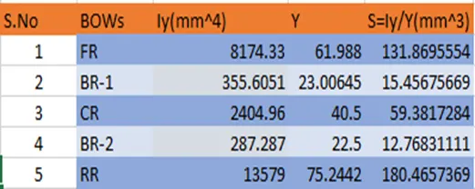
When we compare the values, we can see that the section modulus of the rear roof is higher. And that indicates that if the section modulus increases the moment of resistance increases and hence its load bearing capacity.
Heat distortion criteria
Bow–roof prediction Formula
Heat distortion temperature is the temperature at which metal softens and deforms under a specified load. From Heat distortion criteria, roof strength can be enhanced by appropriate positioning of bow roof rails.
W = [1.73 x 10^(-3) x L] + [1.85 x 10^(-8) x (R^2)/t] + [ 1.10x10^(-3) x l] - 2.68
Judgement Condition: OK< 2.7
Were
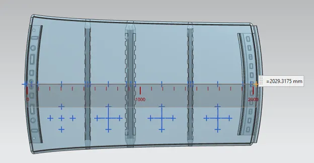
L = Roof Length in X-Direction[mm] (Roof dimension in 0-Y)
R = Roof curvature
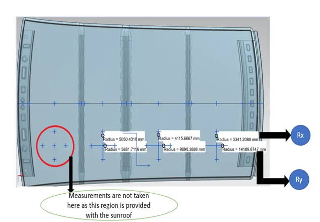
R = 2(Rx*Ry)/(Rx+Ry)
Rx = X curvature
Ry = Y curvature
t = Roof plate thickness [mm]
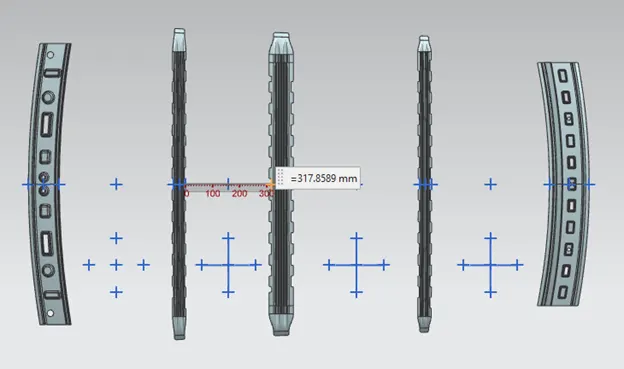
l = Bow Roof Span [mm]
Measuring Rx & Ry(mm)
Measuring L(mm)
Measuring I(mm)
RESULT
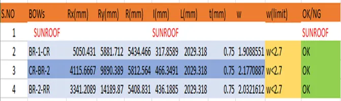
All the values of W are < 2.7 and therefore the design can successfully satisfy heat distortion criteria
Snow load Criteria
When the snow accumulates on the roof it will exert a downward force on the roof which will cause the roof to deform and hence need to withstand this therefore proper positioning of the reinforcements is required which can be calculated using the Snow load criteria.
Snow load Prediction formula
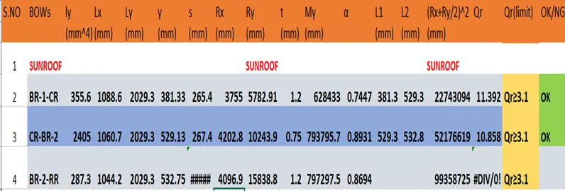
Qr = [Iy x t2] / [α x s x [(Rx + Ry)/2]2 x 10-8]
Were
α = My x Lx2 x 10-12, My = Y(Ly-Y)
Judgement condition = Qr ≥ 3.1
250 ≤ s ≤ 380
t = Roof plate thickness [mm]
Ly = Distance between the front and rear roof Rails on the Vehicle along with 0Y[mm]
Length of Roof panel with the centre point between Roof rail Front /Rear as the front and rear reference point.
Lx = Distance between the Left and Right end of the roof on the Roof BOW [mm]
Width of the roof panel exposed on the surface.
Y = Distance front front Roof Rail to Roof BOW [mm]
s = Distance for which Roof BOW bears divided load [mm]
s = L1/2 + L2/2
Iy = Geometrical moment of inertia of Roof BOW (Y cross-section) [mm4]
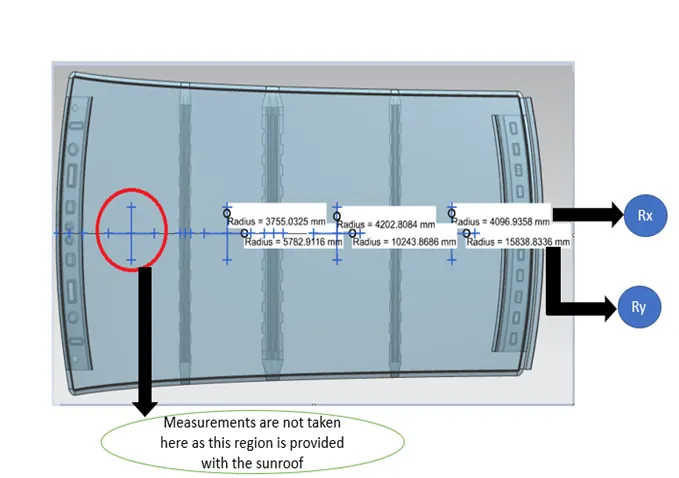
Rx = Lateral direction curvature radius of roof panel Y cross-section on Roof BOW [mm]
Roof panel curvature Radius of the Length Lx in Front view
Ry = Longitudinal Direction curvature radius of the Roof panel X cross-section on Roof BOW [mm]
Roof panel X curvature radius of length s in side view
Measuring the Rx &Ry(mm)
Measuring y (mm)

Measuring Lx(mm)
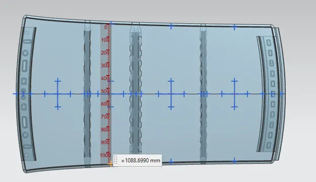
Measuring Ly(mm)
Result
All the values of Qr are >3.1 and therefore the design can successfully satisfy snow load criteria.
Conclusion
The design was successfully completed using the Siemens NX software and snow load, the heat distortion criteria, draft analysis was carried out to ensure if the design was successful to satisfy the requirements.