Roof challenge
Design of Roof
Roof of a car is the potion of the automobile that sits above the passenger protecting the vehicle from outside elements like wind, rain, sun, and other external elements. Newer versions also come with glass roof or sun roof.
Roof consists of various reinforcements along with the external styling surface. The roof consists of front roof rail, rear roof rail, center reinforcement along with number of bow roof rails depending on the length of the vehicle. These reinforcements are added for strength.
Reinforcement Rails-
Front roof rail: Draft angle is provided for deep drawing of the outer styling roof. The height of the flange is decided depending on the visibility criteria and headroom clearance. The front roof rail is joined to the styling component of the roof as well as the windshield. The front portion is spot welded to the ditch area and the portion which comes under the styling area is joined using mastic sealants. Embosses can be provided to add to the strength of the rail.
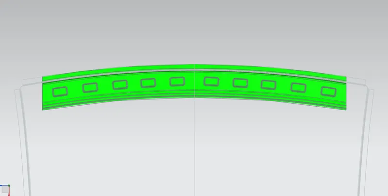
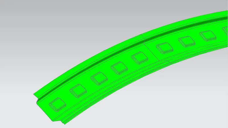
Draft analysis on the front roof rail to check for negative drafts. As seen from the picture it has no negative drafts.
Rear roof rail: It is similar to the front roof rail and is also joined using spot welds in area which aren’t seen from outside and sealed using mastics in the other areas. Visibility clearance as well as headroom clearance is considered for the design.
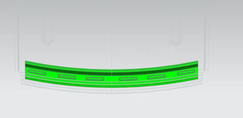
Draft analysis for rear roof rail.
Center reinforcement rail: It is a placed at the center of the roof to add strength. It is spot welded to the ditch area that is joined to the body side. The rail is joined to the outer part with mastic sealants.
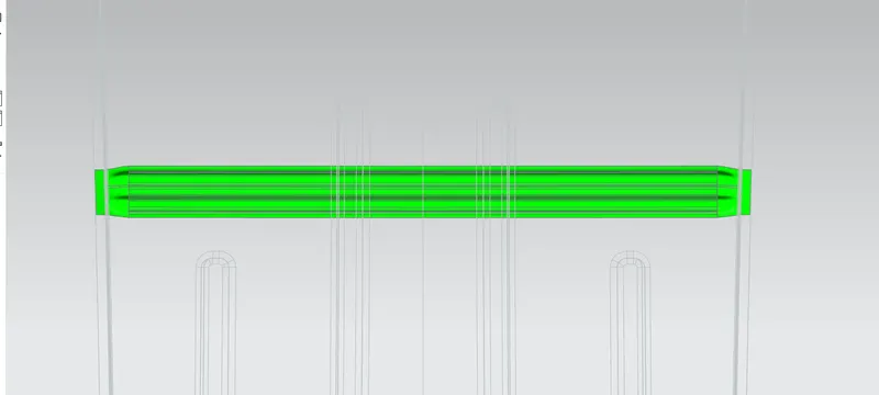
Draft analysis for Reinforcement center.
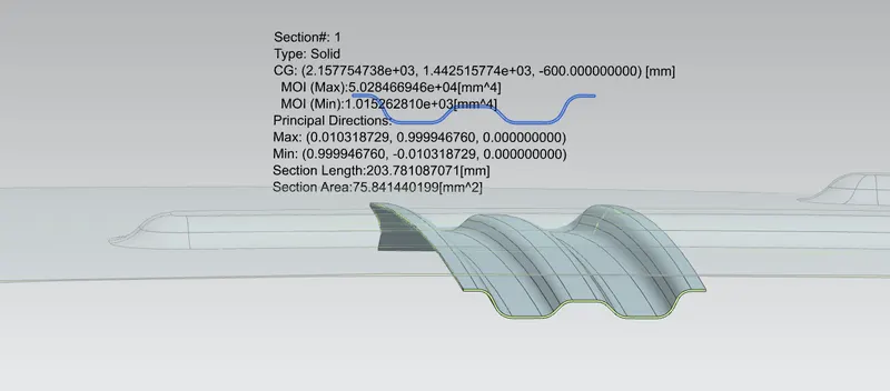
Section modulus of Reinforcement center.
Bow roof rail: This are positioned on the flatter area of the roof. Since, bent elements have better strength. Usually, an average car has two bow roof rails but it can go up-to 4 depending on the length of the car. In case the car has a sun-roof or glass roof the bow roof is placed between the center reinforcement and the outer panel to provide strength.
For this model I have used 2 bow roofs: One between front roof rail and center reinforcement rail. Another between reinforcement center and rear roof rail.
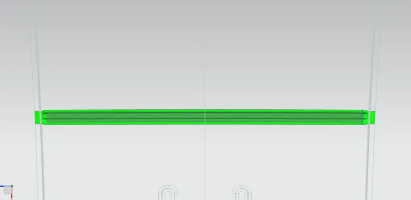
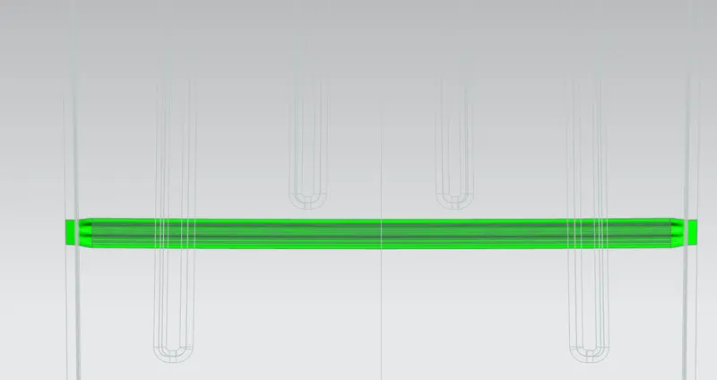
Draft analysis of both bow roof rails.
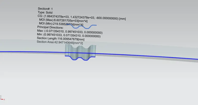
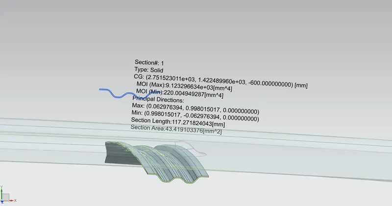
Section Modulus of bow roof one and two.
For both the bow roof and the reinforcement center i have increased the draft angle for better manufacturability.
Curvature study of roof to determine position of reinforcements:
It is done to check whether bow roof and reinforcement center positions are correct i.e., whether they satisfy the heat distortion criteria and snow load criteria.
FR - Front roof rail
BR1/2 - Bow roof 1/2
CR - Center reinforcement
RR - Rear roof rail
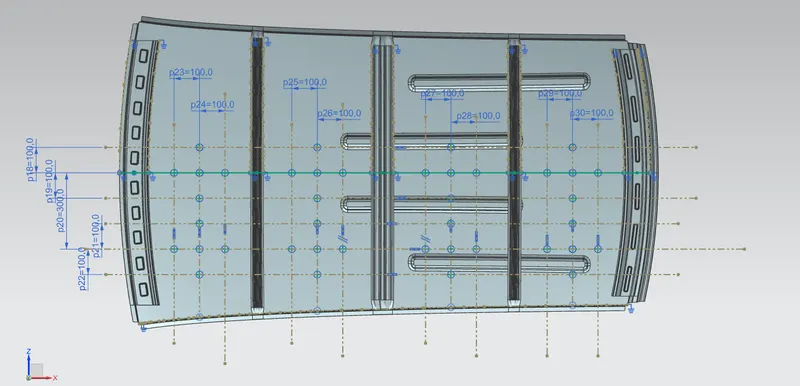
Sketch to locate points to project on the roof surface to find the curvature radius Rx and Ry.
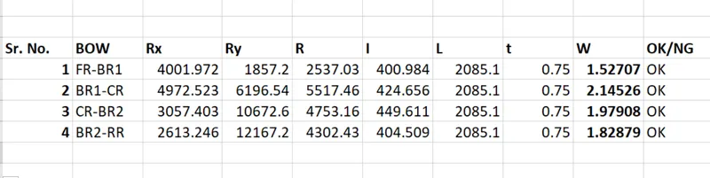
Heat distortion Criteria: it is used to check whether the roof can withstand high temperatures with respect to the reinforcement positionings.
Formula: W = [1.73 x 10^(-3) x L] + [1.85 x 10^(-8) x (R^2)/t] + [ 1.10x10^(-3) x l] - 2.68
Judgement Condition: OK< 2.7
Where,
L = Roof Length in X-Direction[mm](Roof dimension in 0-Y)
R = Roof curvature
R = 2(Rx*Ry)/(Rx+Ry)
Rx = X curvature
Ry = Y curvature
t = Roof plate thickness [mm]
l = Bow Roof Span [mm]
Snow Load Criteria:
Qr = [Iy x t2] / [α x s x [(Rx + Ry)/2]2 x 10-8]
Where
α = My x Lx2 x 10-12 , My = Y(Ly-Y)
Judgement condition = Qr ≥ 3.1
250 ≤ s ≤ 380
t = Roof plate thickness [mm]
Ly = Distance between the front and rear roof Rails on the Vehicle along with 0Y[mm]
Length of Roof panel with the centre point between Roof rail Front /Rear as the front and rear reference point.
Lx = Distance between the Left and Right end of the roof on the Roof BOW [mm]
Width of the roof panel exposed on the surface.
Y = Distance from Front Roof Rail to Roof BOW[mm]
s = Distance for which Roof BOW bears divided load [mm]
s = L1/2 + L2/2
Iy = Geometrical moment of inertia of Roof BOW (Y cross-section )[mm4]
Rx = Lateral direction curvature radius of roof panel Y cross-section on Roof BOW [mm]
Roof panel curvature Radius of the Length Lx in Front view
Ry = Longitudinal Direction curvature radius of the Roof panel X cross-section on Roof BOW [mm]
Roof panel X curvature radius of length s in Side view
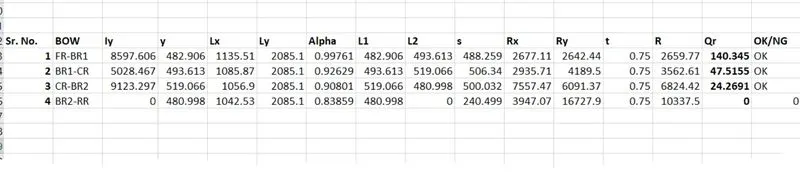
As is seen from the values above, all values of W are less than 2.7 as well as all values of Qr are greater than 3.1. Hence the positions of reinforcements are satisfactory.
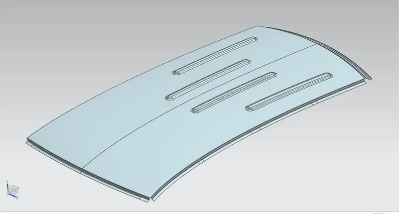
Embossing on roof
Conclusion: Thus, the roof is designed according to the necessary considerations as well as it satisfies the heat distortion criteria and snow load criteria.