DESIGNING OF CAR ROOF (BIW) AND ROOF CALCULATION USING SIEMEN NX
DESIGNING OF CAR ROOF (BIW) AND ROOF CALCULATION USING SIEMEN NX
OBJECTIVE
The main objectives of this project is
- To design and assemble a Car Roof with proper Reinforcements by following the engineering standards using the software Siemen NX
- To check whether the Roof designed is capable to withstand high temperature and load with respect to the positioning of Reinforcements which contributes more strength.
INTRODUCTION
What is a roof?
An automobile roof or car top is the portion of an automobile that sits above the passenger compartment, protecting the vehicle occupants from sun, wind, rain, and other external elements. Because the earliest automobiles were designed in an era of horse-drawn carriages, early automobile roofs used similar materials and designs
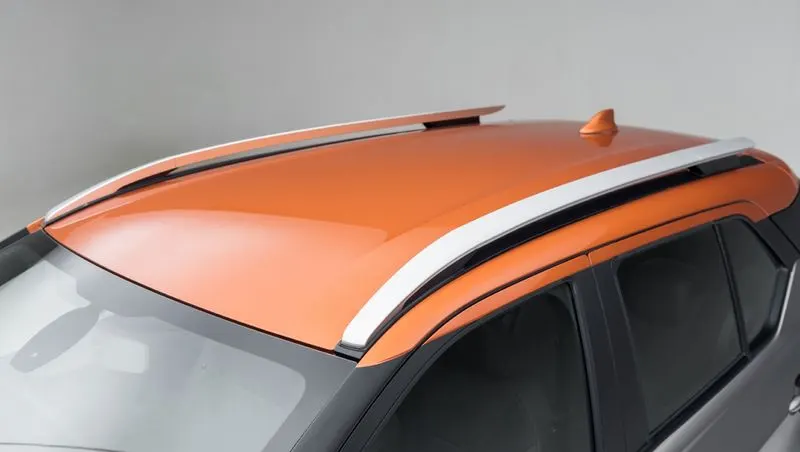
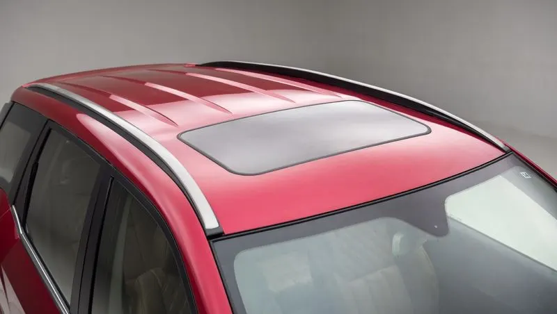
In the past roof was introduced as cover for passenger compartment but later on, it also used as a luggage carrier, sunroof and in recent past years with the introduction of the solar paneled electric vehicle got a major boost in the automotive industry.
In later years, many variations on the automobile roof developed. These include:
In this project we are going to design a conventional/traditional Roof of a car
DESCRIPTION
Here we are creating the Roof , Front And Rear Roof rails along with the three Reinforcements , By taking a pre designed styling surface as the reference.
The Front roof rail and the Rear roof rail are the components , where the front and rear sides of the Roof are attached ,while the other three reinforcements gives enough strength and stiffness to the roof. This assembly of roof include
- Roof outer panel
- Front Roof Rail
- Rear Roof Rail
- Center Reinforcement
- Bow Roof 1
- Bow Roof 2
For designing a car Roof , there are several Design consideration and standards a design engineer must consider in his or her designs.
Major Design considerations
- Material selection
- Visibility criteria
- Head room clearance
- Mastic distance
- Drawability
- DepthHight of the Reinforcements
- Weight and Strength
- Positioning of reinforcement
1) Material selection
BIW is expected to possess a number of significant properties. It must have high tensile strength as well as high stiffness—bending, torsional, static, and dynamic. It must also provide good quality safety both to the car body and to its occupants against crashes of all kinds—front, rear, side, or even rollover, meeting the Federal Motor Vehicle Safety Standard No. 208 [44]. It should also be able to protect occupants from noise, vibration, and/or harshness (NVH) by absorbing or reducing these conditions. Also, it should be easy to weld and form, as well as be highly paintable and easy to design. It should provide a good surface finish that is smooth, and should also be corrosion resistant. Improvement of fuel economy also necessitates the use of lightweight materials in BIW, as it constitutes a significant share of car’s weight; in addition, given environmental concerns in recent times, it is also expected to be recyclable. Given such extensive requirements, only steel and aluminum have been used for making BIW; the former is preferred for its high strength and low cost, while the latter is preferred for its lower density that helps reduce car weight .
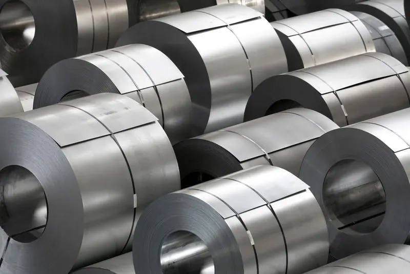
Materials for each components are given below
Front Roof Rail – SP783AJQ
Rear Roof Rail - SP783AJQ
Center Reinforcement – SP153-980PQ
Bow Roof 1&2 – SP121BQ
2) Visibility criteria
Visibility of the driver in an automotive is one of the major design consideration. Thus the Visibility criteria lines should be given to a Design engineer from the project team in order to consider it in his/her designs.
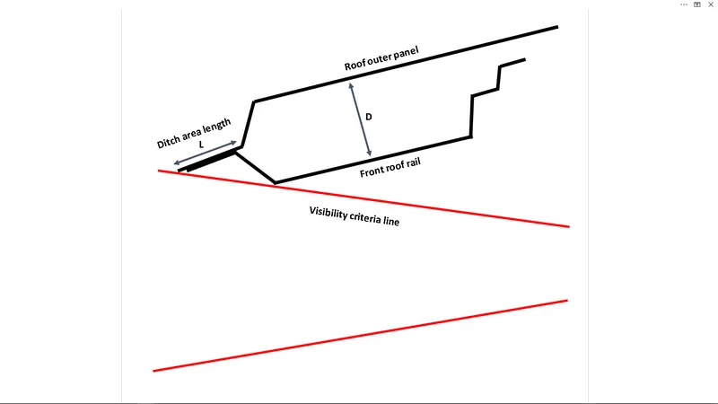
While designing the Roof outer panel and the front roof rail we need to consider the visibility criteria. The picture below gives a clear understanding about this visibility criteria
Here as the length L ‘which is the length of the front ditch area ‘ increases , its going to reduce the visibility. So it is one of the consideration here
Also as the depth of the Front roof rail D increases , again the visibility decreases. This is the second consideration
So its mandatory to maintain the visibility criteria which is given from the project management team in Both of these designs.
3) Head Room Clearance
Here the Factor which effects the head room clearance is the width of the Front Roof Rail. As the width of the Front Roof rail increases ,the Head room clearance is getting reduced.so its necessary to maintain the width of the Front Roof Rail according to the Head room clearance data given by the project team.
4) Mastic Distance
Mastics are the rubber compounds which is applied in between two sheet metal BIW components where spot welding is not applicable.
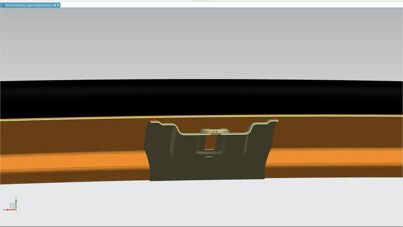
Mastic distance here is the distance between the roof outer panel and the surface of the reinforcement where the mastic are applied. This distance must be maintained in between 2 mm to 8 mm
5) Drawability (Draft Analysis)
To understand what is drawability , first we should know what is deep drawing
Deep drawing
Deep drawing is a sheet metal forming process in which a sheet metal blank is radially drawn into a forming die by the mechanical action of a punch. It is thus a shape transformation process with material retention. The process is considered "deep" drawing when the depth of the drawn part exceeds its diameter. This is achieved by redrawing the part through a series of dies. The flange region (sheet metal in the die shoulder area) experiences a radial drawing stress and a tangential compressive stress due to the material retention property. These compressive stresses (hoop stresses) result in flange wrinkles (wrinkles of the first order). Wrinkles can be prevented by using a blank holder, the function of which is to facilitate controlled material flow into the die radius. The feasibility of this deep drawing is called Drawability
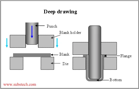
So While designing we must also consider the feasibility of deep drawing, otherwise the model will not be able to manufacture.
Draft analysis in Siemen NX is one of the tool used to study the deep drawing feasibility easily through checking draft angle in the various faces .The Designer should Define a tooling direction in-order to check the draft angles
6) DepthHight of the Reinforcements
Depth or the height of the reinforcements (Bow roofs) are another design consideration. In a car the Bow roofs lies in between the Head liner and the Roof outer panel. So as the depth of the bow roof increase the interior space is get reduced. In common cases the depth of the bow roofs doesn’t exceed 15 mm , But in some cases it changes according to cars.
7) Weight and Strength
This factor is compulsory considered in each and every components of BIW. Because todays car manufactures mostly focusing on reducing the over all weight of the car with out compromising the strength of the parts . So its better to remove some extra materials from the designs with out losing its strength. One of the method used to strengthen the parts are the Embosses
Embossing
Sheet metal embossing is a stamping process for producing raised or sunken designs or relief in sheet metal. This process can be made by means of matched male and female roller dies, or by passing sheet or a strip of metal between rolls of the desired pattern .Adding of embosses to a sheet metal part , drastically increase the strength of the part.
8) Positioning of reinforcements
Positioning of the bow roofs have the major role in the strength of the Roof. The roof must be capable to withstand high temperature and load with respect to the positioning of Reinforcements which contributes more strength.
So we have two criteria to check whether the position of the Bow roof are correct or not. They are
Heat distortion Criteria
The heat distortion value ‘W’ must be less than 2.7 to ensure that , the roof can withstand high temperature .
Snow Load Criteria
In the winder season , in some countries there will be a huge load of snow on the roof top of the car. So for the roof it is necessary to have enough strength to bear this snow load. Thus the snow load value ‘Qr’ for the roof must be grater than 3.1
Taking all these design consideration we are creating all the components of the roof one by one
The first part to be created is the Roof outer panel
PROCEDURE
1) Roof outer panel
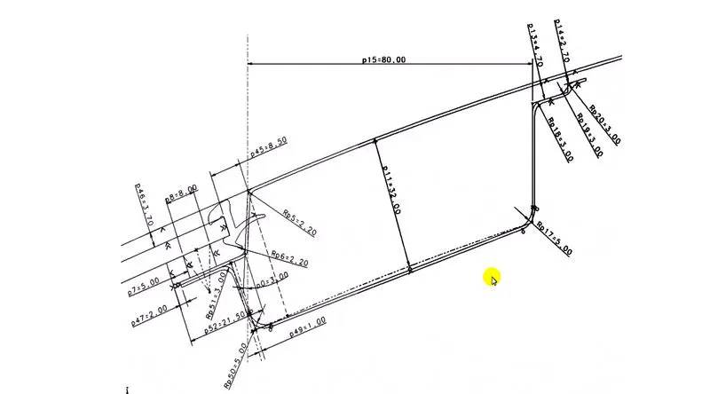
Here I have the styling surface as reference, so I only need to create the side flange and the ditch area in the roof. As I doesn’t have any data from any other parts of the car , I am taking a given master sketch as another reference.
So using the master sketch I have created a side flange with an opening angle of 3 degree and another flange , which is the ditch area od length 21.5 mm
After creating the part I have checked the feasibility of deep drawing
Draft analysis
For draft analysis I have defined a tooling direction which is perpendicular to the part

I have drawn a perpendicular line and then it is tilted to 5 degrees for achieving an accurate tooling direction
Here I could find a negative draft angle at the rear side of the roof. But it is negligible in this case because I have assumed a car having backdoor with the spoiler in it . So while opening the back door the Spoiler should go inside thiss space. Thus a positive draft angle is cannot be achieved
2) Front Roof Rail
The same master sketch taken for creating the ditch area in the roof is taking here as the reference. I have used wave geometry linker to take the roof outer surface and offset it to needed values and them trimmed of the extra materials
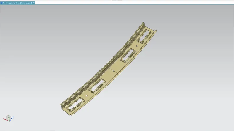
One of the major consideration is the depth/height of the Front roof rail as it effects the visibility criteria. Here we doesn’t have any data rather than the master sketch. So im taking 32 mm( which is given in the master sketch) as the height of the Front roof rail And the overall width to 124.2 mm which is not going to reduce the head room clearance
Draft analysis
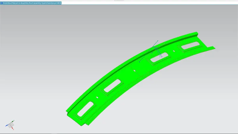
Same as in the Front roof rail ,I have drawn a perpendicular line and then it is tilted to 5 degrees for achieving an accurate tooling direction. After analysis there are no negative draft angles shown.
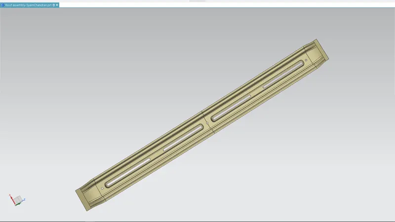
3) Center Reinforcement
As in the Front Roof rail I have used wave geometry linker to take the outer surface of the roof. Then offset it to certain values and trimmed the extra materials to create the part. Total width of the Center reinforcement I have created is 92 mm and the height/depth is 15 mm .
Draft analysis
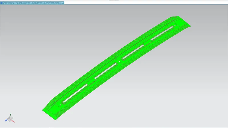
Here I have taken the Y axis as the tooling direction and after the draft analysis I could find zero negative draft angle
4) Bow Roof 1&2
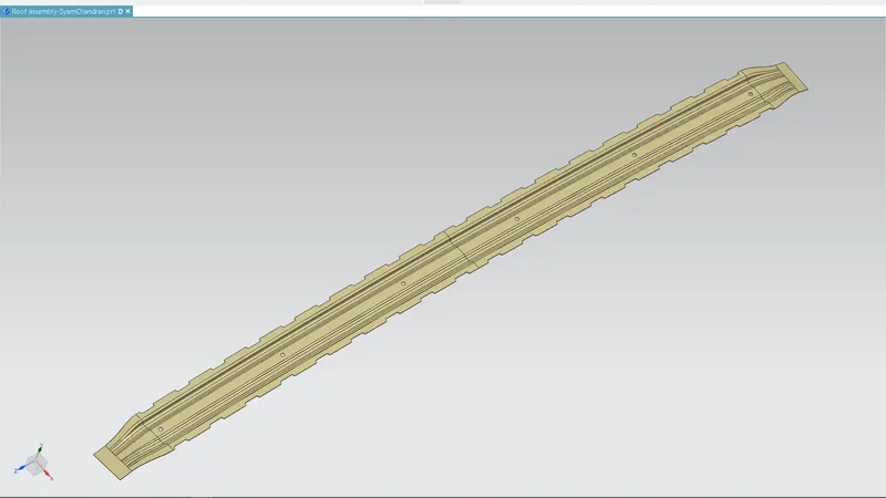
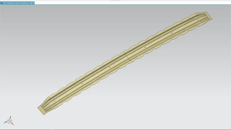
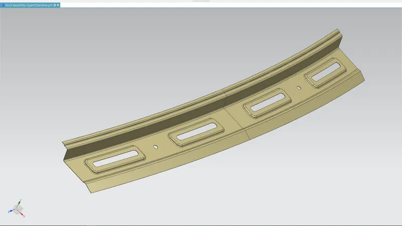
Apart from the center reinforcement I have created two Bow roofs , one in between the Rear roof rail and the center reinforcement and the other is in between Rear roof rail and the center reinforcement. Method of creation for each Bow roof are same as the center reinforcement . But here the width and the Height varies , Width is 68 mm and the height/depth is 8 mm. Foe both the Bow roofs these values are same. Also to reduce the weight of the part I have done some cut outs From the top surface of the Bow roof as shown in the figure
Draft analysis
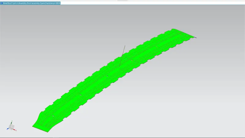
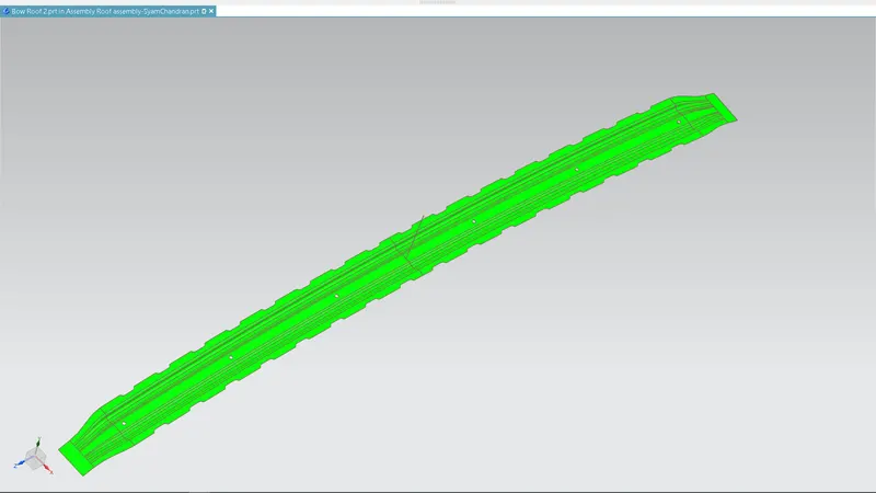
There are no negative draft angles
5) Rear Roof Rail
For the Rear roof rail , i have taken 126.5 mm as its over all width and 35 mm as the Depth/height. Designing of the Rear roof rail is exactly same as the Front roof rail.
Draft analysis
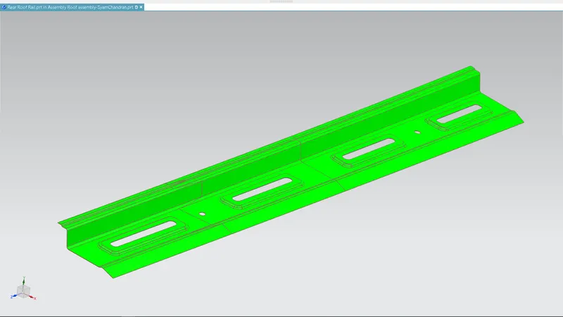
Here I have taken the y axis as the tooling direction and after analysis there is no negative draft angles
After designing and the assembly is complete , we should check whether the positions of the reinforcements are correct and whether they can give enough support to the roof to bear enough load .Also whether the roof can withstand high temperature with out any deformation .For that we need to do two calculation
- Heat Distortion calculation
This is the calculation to check whether the roof can withstand high temperature with respect to the positioning of the reinforcements with out any deformation .
The Heat distortion criteria is W < 2.7
We have the equation W = [1.73 x 10^(-3) x L] + [1.85 x 10^(-8) x (R^2)/t] + [ 1.10x10^(-3) x l] - 2.68
Judgement Condition : OK< 2.7
Where
L = Roof Length in X-Direction[mm](Roof dimension in 0-Y)
R = Roof curvature
R = 2(Rx*Ry)/(Rx+Ry)
Rx = X curvature
Ry = Y curvature
t = Roof plate thickness [mm]
l = Bow Roof Span [mm
The measured values and the calculations are depicted in the table below .Here in each cases this model pass the heat distortion criteria
|
CASE |
Ry (mm) |
Rx (mm) |
R (mm) |
L (mm) |
I(mm) |
t (mm) |
W |
W limit |
PassFail |
|
|
1 |
B/W FR Rail & BR 1 |
2525.0578 |
5739.5412 |
3507.169138 |
2025 |
378.3 |
0.75 |
1.542785806 |
W<2.7 |
Pass |
|
2 |
B/W BR 1 & CR Rail |
6187.9742 |
4974.6596 |
5515.376713 |
2025 |
428.6 |
0.75 |
2.045054714 |
W<2.7 |
Pass |
|
3 |
B/W CR rail & BR 2 |
10624.5433 |
3968.9812 |
5779.085459 |
2025 |
528.5 |
0.75 |
2.228413109 |
W<2.7 |
Pass |
|
4 |
B/W BR 2 & RR Rail |
14729.6058 |
3258.8244 |
5336.896911 |
2025 |
381.3 |
0.75 |
1.94524756 |
W<2.7 |
Pass |
- Snow Load calculation
In the winder season , in some countries there will be a huge load of snow on the roof top of the car. So for the roof it is necessary to have enough strength to bear this snow load.

The snow criteria is Qr ≥ 3.1
We have the equation
Qr = [Iy x t2] / [α x s x [(Rx + Ry)/2]2 x 10-8]
Where
α = My x Lx2 x 10-12 , My = Y(Ly-Y)
Judgement condition = Qr ≥ 3.1
250 ≤ s ≤ 380
t = Roof plate thickness [mm]
Ly = Distance between the front and rear roof Rails on the Vehicle along with 0Y[mm]
Length of Roof panel with the center point between Roof rail Front /Rear as the front and rear reference point.
Lx = Distance between the Left and Right end of the roof on the Roof BOW [mm]
Width of the roof panel exposed on the surface.
Y = Distance front Front Roof Rail to Roof BOW[mm]
s = Distance for which Roof BOW bears divided load [mm]
s = L1/2 + L2/2
Iy = Geometrical moment of inertia of Roof BOW (Y cross-section )[mm4]
Rx = Lateral direction curvature radius of roof panel Y cross-section on Roof BOW [mm]
Roof panel curvature Radius of the Length Lx in Front view
Ry = Longitudinal Direction curvature radius of the Roof panel X cross-section on Roof BOW [mm]
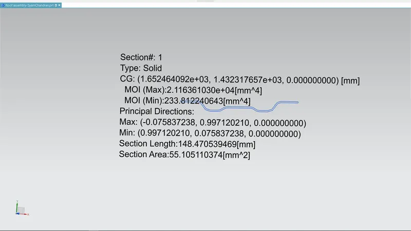
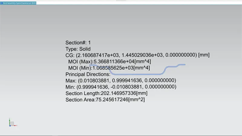
For the Snow load calculation first of all we need to find the section inertia of the three Reinforcements which are Bow roof 1, Bow roof 2 and the Center Reinforcement
Bow Roof 1
Center Reinforcement
Bow Roof 2
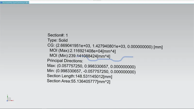
The measured values and the calculations are depicted in the table below
|
CASE |
L1 |
L2 |
S |
|
B/W FR Rail & BR 1 |
468 |
508.5 |
488.25 |
|
B/W BR 1 & CR Rail |
508.5 |
508.5 |
508.5 |
|
B/W CR rail & BR 2 |
508.5 |
472.9 |
490.7 |
|
B/W BR 2 & RR Rail |
0 |
|
CASE |
Rx (mm) |
Ry (mm) |
Lx |
Ly (mm) |
Y (mm) |
Iy (mm^4) |
s (mm) |
My (mm) |
α |
t (mm) |
Qr |
Qr Limit |
OK/NG |
|
|
1 |
B/W FR Rail & BR 1 |
4542.6632 |
2583.2275 |
1135.7 |
2025 |
468 |
233.8122 |
488.25 |
728676 |
0.9398 |
0.75 |
2.2577 |
Qr ≥ 3.1 |
NG |
|
2 |
B/W BR 1 & CR Rail |
3764.1028 |
6096.387 |
1082.4 |
2025 |
508.5 |
1068.58 |
508.5 |
771140.25 |
0.9034 |
0.75 |
5.3826 |
Qr ≥ 3.1 |
OK |
|
3 |
B/W CR rail & BR 2 |
4279.475 |
11134.579 |
1054.3 |
2025 |
508.5 |
239.141 |
490.7 |
771140.25 |
0.8571 |
0.75 |
0.5384 |
Qr ≥ 3.1 |
NG |
|
4 |
B/W BR 2 & RR Rail |
3971.2349 |
16594.584 |
1039.5 |
2025 |
472.9 |
Here we can see that in the two cases the Qr value doesn’t meet the Snow load criteria , ie the QR value is not grater than or equal to 3.1. This means that ,the bow roofs cannot give enough strength to the roof with respect to that position. So to pass the snow load criteria its needed to recreate the Bow roof by changing its position .
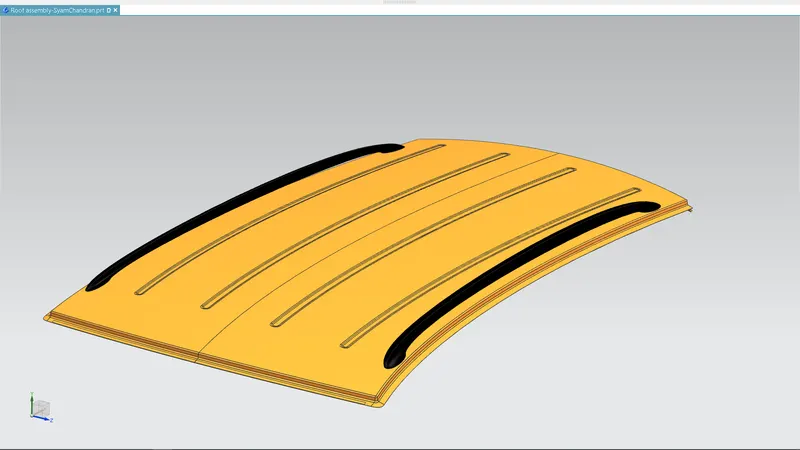
As this process will take very long time and the manufacturer doesn’t have much time ,apart from recreating the Bow roofs its possible to increase the strength of the roof by adding proper Embosses on outer roof panel .
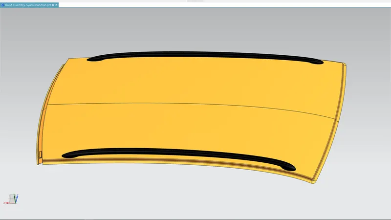
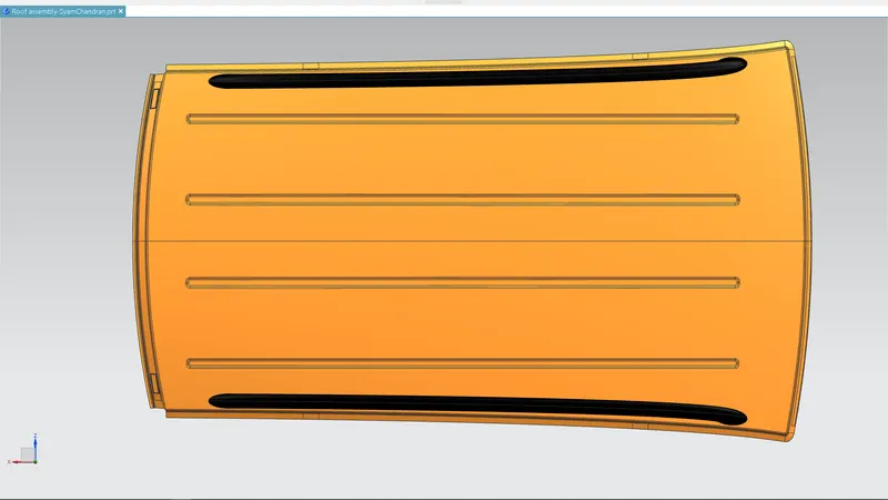
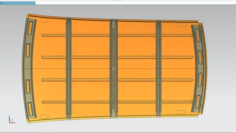
So here I have created Some embosses as shown in the picture with out affecting the good looks of the Roof
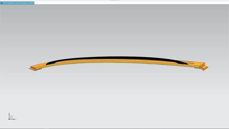
The Final model after doing the embosses is given below
CONCLUSION
- Roof assembly has been made by following all the engineering standards and considerations
- Heat distortion criteria is been successfully passed
- Snow load criteria has been failed in some cases and to over come that Embosses are added on the Roof outer panel