DESIGNING ROOF FOR A VEHICLE.
TITLE: To design and develop the roof of a car along with essential flanges and reinforcement by following the master section and design parameters.
OBJECTIVE:
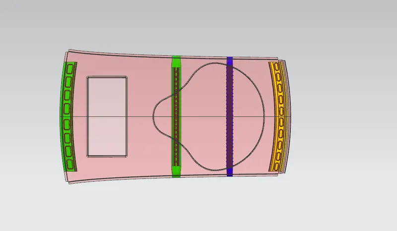
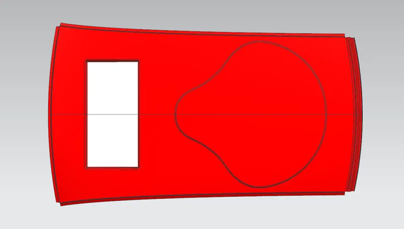
- The objective of this project is to design car roof with essential flanges and reinforcements like ditch area, front roof rail, bow roofs, central roof rail and rear roof rail for the given styling surface.
- Perform a curvature study on the roof and perform the calculations for the heat distortion and snow load criteria to determine whether the bow roofs are at the correct positions.
- Finding moment of inertia and section modulus for Bow roofs, central roof rail, front roof rail and rear roof rail.
- Perform the draft analysis for each reinforcement.
INTRODUCTION:
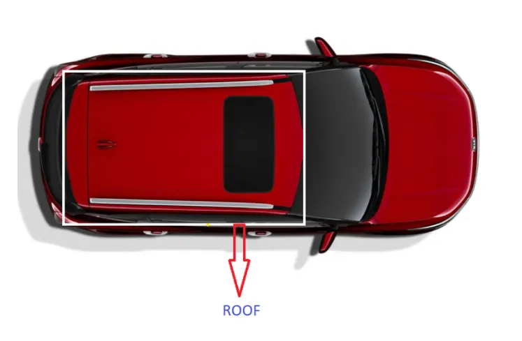
The roof is an important component in automotive BIW structure where it helps passenger to protect from external factors while in traveling such as harsh climatic conditions such as rain, sun and snow. It also acts as a cross member between body sides of the car body and provides provisions for front windshields, backdoor (in case of hatchback vehicles). Roof assembly also one among the parts which provide safety for rollover accidents.
The roof is an assembly of many parts like Front roof rail, bow roof, Bow roof center, and reinforcement center. The number of bow roofs is based on the length of the roof and sometimes even the bow roof center is avoided in cases like small cars. The roof is attached to the body of the car using mastic sealants provided between bow roofs and the front and rear rails. Roof is connected to A-pillar, B-Pillar and C-Pillar to cover the Front and rear door. Roof is supported by reinforcement bow-roof with front and back roof rail.
DESIGN METHODOLOGY:
Ditch area:
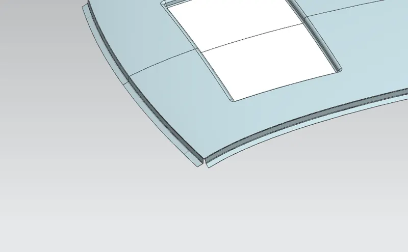
Ditch area is the extended part of the roof to which Roof rails and bow roofs are concealed using spot welds. For designing the part there are some factors we consider and those are Headroom clearance, Driver visibility criteria, wind shield clearance and Back door. The thickness we give is 0.75mm.
Front roof rail:
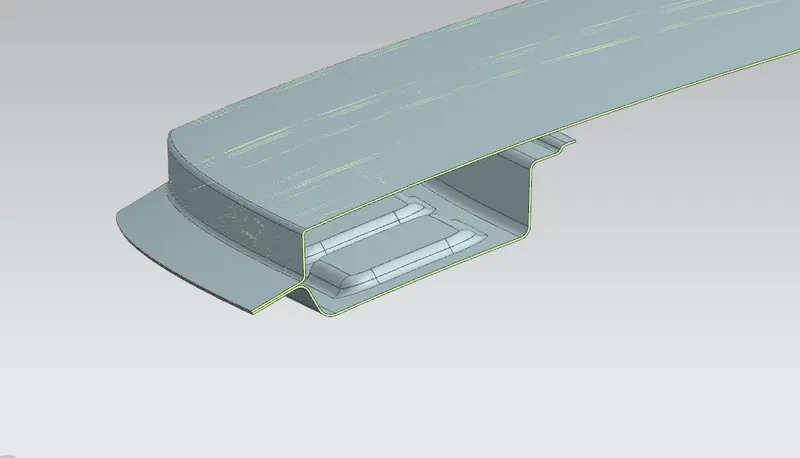
It is the support that is joined with the windshield glass, bodyside outer and the inner panels. It is usually made with thickness of 0.75 mm. A draft angle of 3-5 degrees is provided for deep-drawing operation. The visibility criteria and the headroom clearance of the passenger are taken into consideration for the bottommost flange. Windshield end and the roof end are spot welded and the other end of the front roof rail is joined with the roof using mastic sealants for increased strength.
Rear Roof Rail:
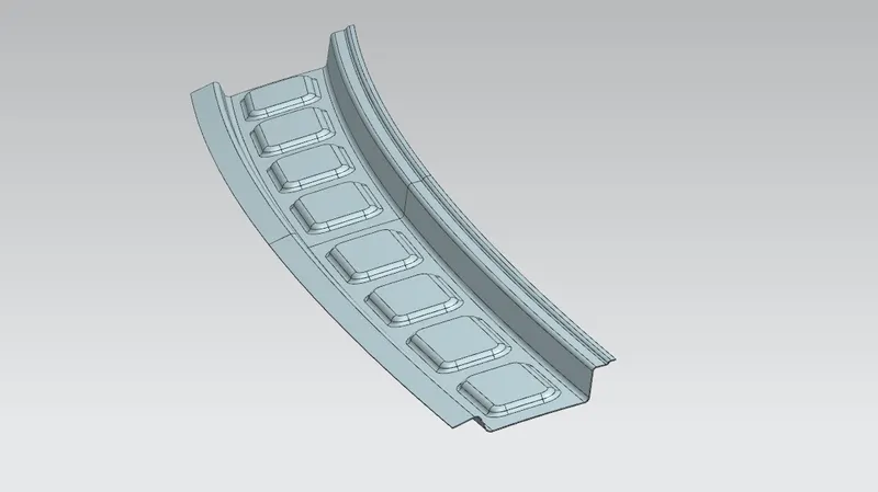
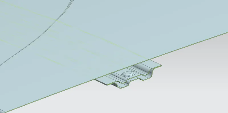
Rear Roof Rail is the support that is joined to the backdoor, the bodyside outer and the inner panels. Inputs from the backdoor design is also taken to accommodate the required clearance along with headroom clearance and the rear visibility criteria while designing the rear roof rail. Spot welds are applied at the backdoor end of the rail and the other end is joined with the roof using mastic sealants.
Bow roof:
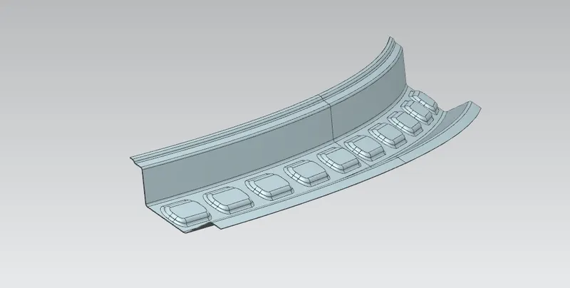
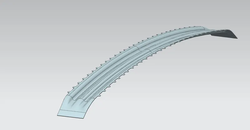
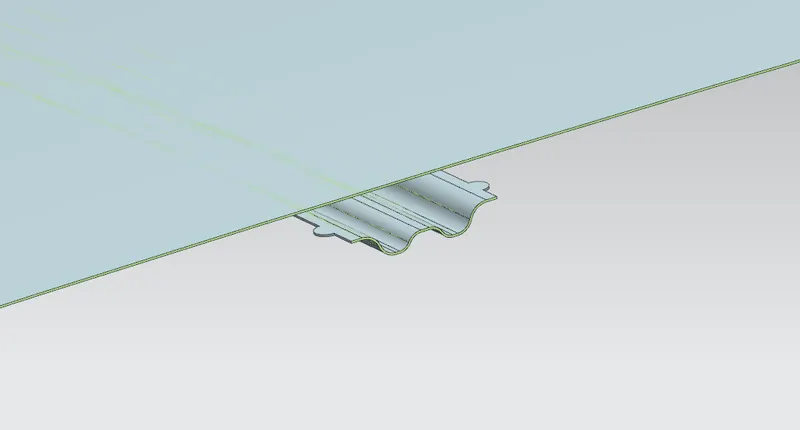
All the bow roof rails were placed between the front and rear roof rails. Bow roof rails were added to increase the stiffness of the roof since it has the large flat surface. To increase the curvature result of the roof where it needs to withstand the heat distortion and snow load criteria the bow roofs were positioned as per the standards. The bow roofs were provided with mastic points since the joining process will be done using the mastic sealants. The bow roof position needs to satisfy the head room clearance and draft analysis for Deep Drawing.
Central Roof Rail (Reinforcement center):
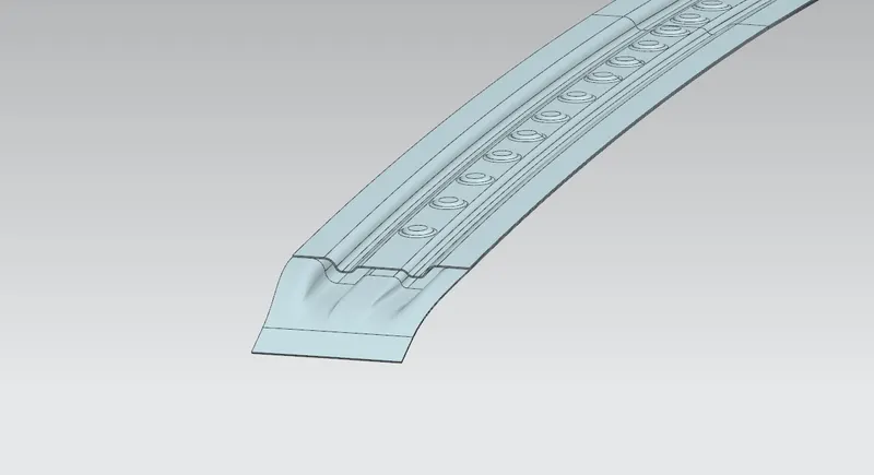
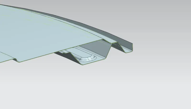
For this project I placed central roof rail between the front roof rail and bow roof as my roof consist moonroof, but it can also be swapped between the Bow Roofs but it should be positioned as center of the roof as much as possible. The center roof rail was designed to have a reinforcement roof rail which helps the roof of a car to increase the efficiency in curvature study. For creating the Mastic Points and Embosses on the Center Roof Rail again the Head room clearance must be taken into account. The reinforcement provided will increase the Geometric MOI of the part drastically.
POSITIONING THE RAILS:
HEAT DISTORTION STUDY ON THE ROOF:
The heat distortion study plays a major role in sheet metal usage. Heat distortion temperature is a temperature limit above which the material cannot be used for the structural applications. This study is used to predict the heat distortion temperature at where the material starts to soften when exposed to a fixed load at elevated temperature. In order to avoid bending or damages on the roof, based on the heat distortion temperature, this study will predict the bow roof position which helps to strengthen the roof.
Bow – roof prediction Formula
W = [1.73 x 10^ (-3) x L] + [1.85 x 10^ (-8) x (R^2)/t] + [ 1.10x10^ (-3) x l] - 2.68
Where,
L = Roof Length in X-Direction[mm](Roof dimension in O-Y)
R = Roof curvature
R = 2(Rx*Ry)/(Rx+Ry)
Rx = X curvature
Ry = Y curvature
t = Roof plate thickness [mm]
l= Bow Roof Span [mm]
Judgement Condition: OK< 2.7> 3.1
|
POSITION |
Rx |
Ry |
R |
l |
L |
t |
W |
OK/NG |
|
CR - BOW 1 |
3950.14 |
10721 |
5772.62 |
416.67 |
2031.46 |
0.75 |
2.11 |
OK |
|
BOW 1 - REAR RAIL |
3236.47 |
14878.28 |
5316.45 |
382.37 |
2031.46 |
0.75 |
1.952 |
OK |
SNOW LOAD CRITERIA:
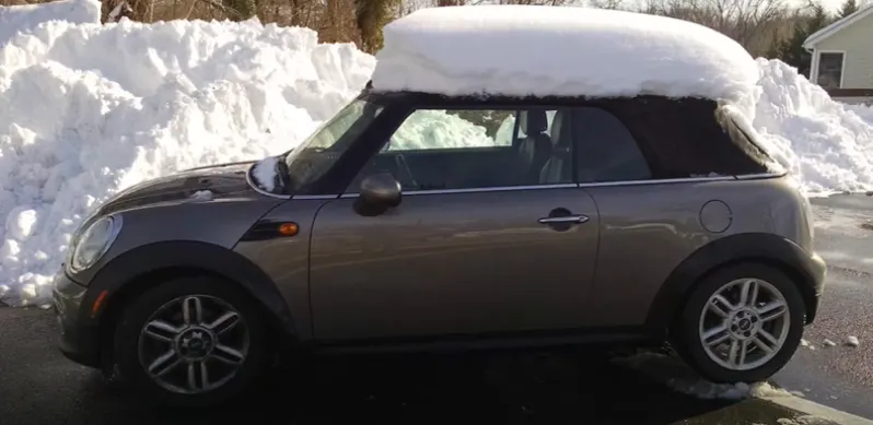
Snow load criteria study is done to check the ability of the roof to withstand snowfall and bounce back to its original shape without any permanent deformation once the load is removed.
Snow load Prediction Formula:
Qr = [ly × t^2] / [α × s × [(Rx + Ry) ÷2] ^2 × 10^-8]
Where,
α = My × Lx^2 × 10^-12 ,
My = Y(Ly-Y)
Judgement condition = Qr ≥ 3.1
250≥ s≥ 380
t = Roof plate thickness [mm]
Ly = Distance between the front and rear roof Rails on the Vehicle along with OY [mm] Length of Roof panel with the center point between Roof rail Front /Rear as the reference point of the front and the rear.
Lx = Distance between the Left and Right end of the roof on the Roof BOW [mm] Width of the roof panel exposed on the surface.
Y = Distance Front Roof Rail to Roof Bow[mm]
s = Distance for which Roof BOW bears divided load [mm]
s = L1/2 + L2/2
ly = Geometrical moment of inertia of Roof BOW (Y cross-section) [ mm4]
Rx = Lateral direction curvature radius of roof panel Y cross-section on Roof BOW [ mm] Roof panel curvature Radius of the Length Lx in Front view
Ry = Longitudinal Direction curvature radius of the Roof panel X cross-section on Roof BOW [mm]
|
POSITION |
Lx |
Ly |
Rx |
Ry |
α |
t |
s |
Y |
Iy |
Qr |
RESULT |
|
CR - BOW 1 |
1057.82 |
2031.46 |
4287.71 |
11253.70 |
0.84 |
.75 |
478.78 |
488.60 |
478.11 |
1.10 |
NG |
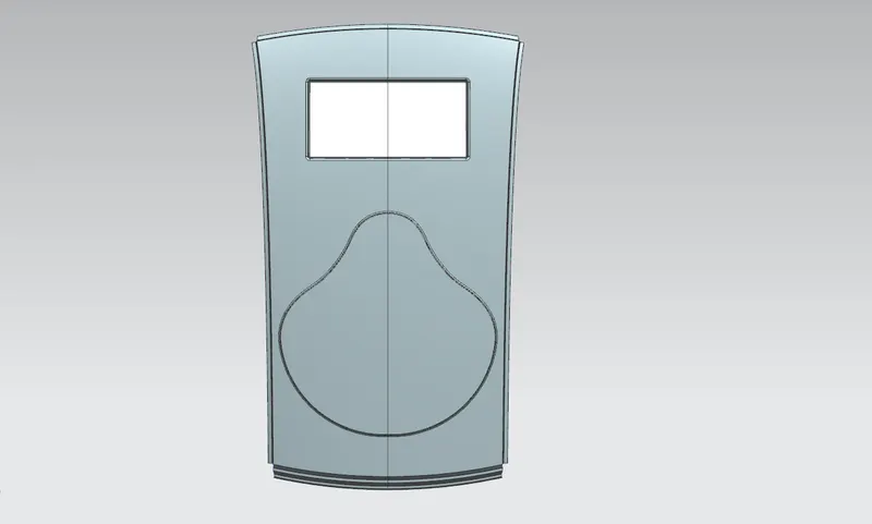
As per snow load criteria mine roof design fails under snow load. For improving this and overcoming this failure I add an emboss to the upper face of the roof to improve the strengh of the roof.
SECTION MODULUS:
Section modulus is a geometric property for a given cross section used in the design of beams or flexural members. It is the direct measure of the Flexural strength of the section. Higher the section modulus of a structure, the more resistive it becomes to bending.
Section modulus (S) is defined as the ratio of polar moment of Inertia (I) to the radius of the shaft or the distance from the neutral axis and the extreme end of the object (y)
Section modulus (S) = I/y
Where,
S = Section modulus
I = Moment of Inertia
Y = Distance between the neutral axis to the farthest fiber.
Front Roof Rail Section Modulus:
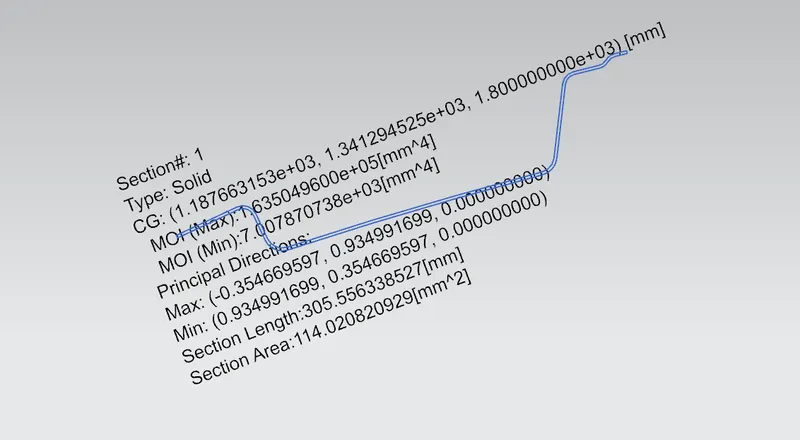
I = 7007 mm⁴
Y = 119.05 mm
S = I/Y = 58.85 mm³
Rear Roof Rail Section Modulus:
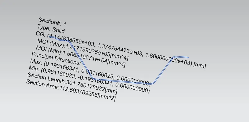
I = 15068 mm⁴
Y = 120.04 mm
S = I/Y = 125.52 mm³
Bow Roof Rail Section Modulus:
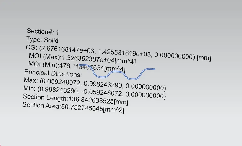
I = 478.4 mm⁴
Y = 56.66 mm
S = I/Y = 8.44 mm³
Reinforcement Center Section Modulus:
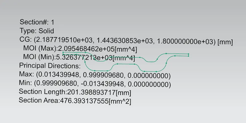
I = 5326 mm⁴
Y = 87.94 mm
S = I/Y = 60.56 mm³
DRAFT ANALYSIS:
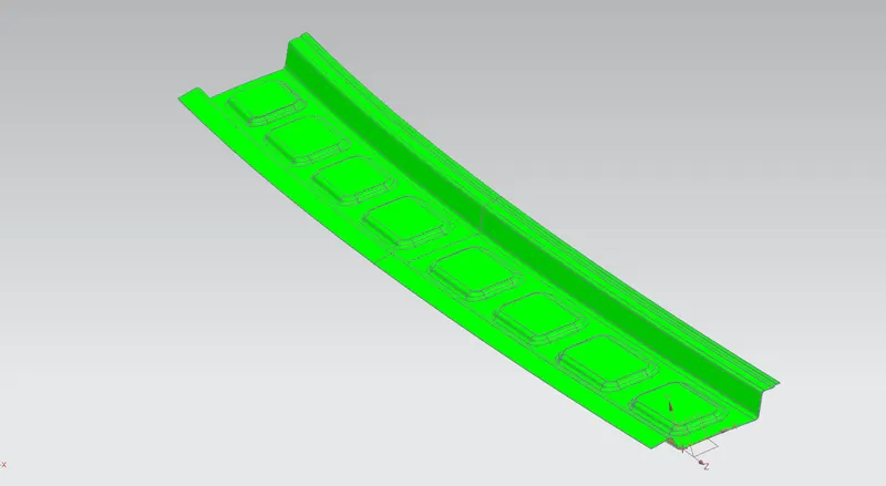
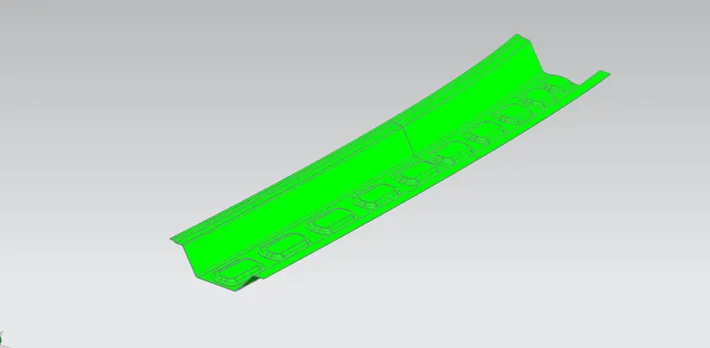
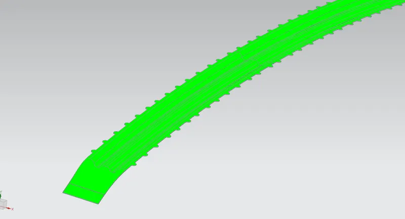
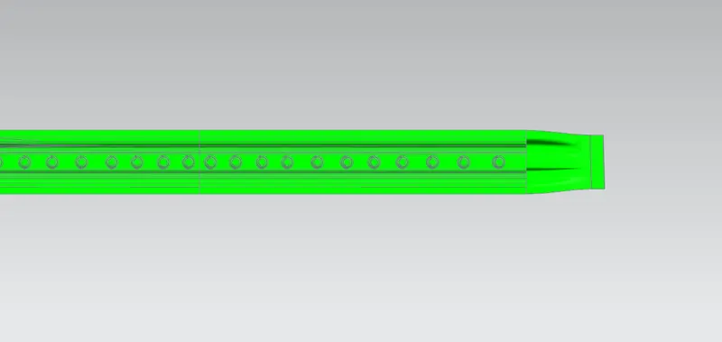
The Draft Analysis command enables you to detect if the part you drafted will be easily removed. This type of analysis is performed based on color ranges identifying zones on the analyzed element where the deviation from the draft direction at any point, corresponds to specified values.
DRAFT ANALYSIS OF FRONT ROOF RAIL:
DRAFT ANALYSIS OF REAR ROOF RAIL:
DRAFT ANALYSIS OF BOW ROOF RAIL:
DRAFT ANALYSIS OF REINFORCEMENT CENTER RAIL:
DIFFERENT VIEWS OF ROOF:
Section view with front roof rail:
Section view with rear roof rail:
Section view with bow roof rail:
Section view with reinforcement center:
All the reinforcement:
Roof:
CONCLUSION:
- Successfully designed car roof with essential flanges and reinforcements like ditch area, front roof rail, bow roofs, central roof rail and rear roof rail for the given styling surface.
- Get hands on experience on how to Perform curvature study on the roof and perform the calculations for the heat distortion and snow load criteria to determine whether the bow roofs are at the correct positions.
- Find out the moment of inertia and section modulus for Bow roofs, central roof rail, front roof rail and rear roof rail.
- Successfully did the draft analysis for each reinforcement.